

Ambit BuildGates Synthesis User Guide
Viewing the Schematic Design
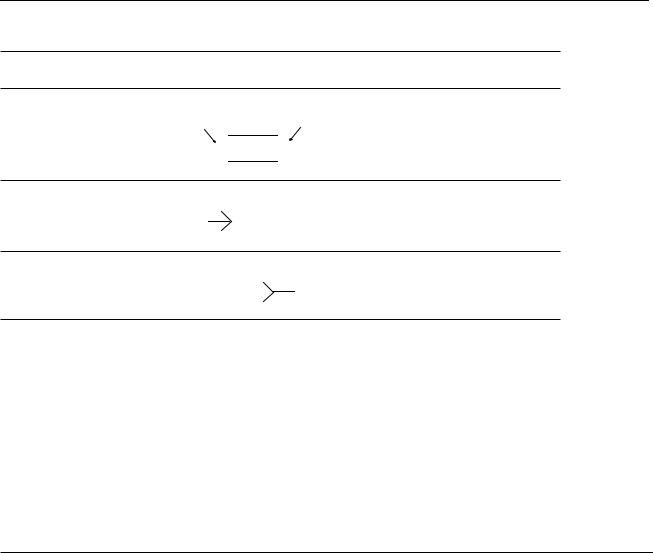
Table 5-3 Object Descriptions, continued
Object |
Description |
Default Color |
Pin
Input Pin |
Output Pin |


 Net Item


Blue; connected to yellow net
On-page
Connector
Net Name
Blue
Highlighted on the newly displayed page.
Off-page
Connector
Net Name
Blue
Highlighted on the newly displayed page.
Accessing Context-Sensitive Pop-Up Menus
The schematic viewer uses seven basic context-sensitive pop-up menus. The Commands pop-up menu is displayed by clicking the right mouse button in the background area of the schematic viewer. The other six pop-up menus are displayed by clicking the right mouse button on any of the basic objects described in Table 5-3.
The seven pop-up menus are defined in the following tables.
Table 5-4 Commands Pop-Up Menu
Menu Item |
Action |
|
|
Extract Fanin Cone |
Extract a fanin cone for use in another module. Displays an extract |
|
bar between the module bar and the schematic. For a description of |
|
the task, refer to “Extracting Logic Cones” on page 131. |
Extract Fanout Cone |
Extract a fanout cone for use in another module. Displays an extract |
|
bar between the module bar and the schematic. For a description of |
|
the task, refer to “Extracting Logic Cones” on page 131. |
Pin to Pin Path ... |
Displays the pin-to-pin panel between the module bar and the |
|
schematic (see Figure 5-2 for a sample panel). Specify the to-from, |
|
from-to, or between pins for the desired object. |
September 2000 |
114 |
Product Version 4.0 |

|
Ambit BuildGates Synthesis User Guide |
|
|
Viewing the Schematic Design |
|
|
|
|
Table 5-4 Commands Pop-Up Menu |
|
|
|
|
|
Menu Item |
Action |
|
|
|
|
Generate all Pages |
Force the generation of the page for the displayed module. If the |
|
|
schematic is multipage and shows unsplit (unspl) in the module title |
|
|
bar, the pages are regenerated and scaled to fit on multiple pages. |
|
|
This command performs the same function as View–Schematic |
|
|
Preferences–Paging–Page Size, except the paging is performed |
|
|
only once and does not affect the schematic preferences or paging |
|
|
on other modules. |
|
Regenerate Current |
Regenerate and center the current schematic page. |
|
Page |
|
|
Worst Path |
Highlight the worst path on the displayed schematic. |
|
Worst Endpoints:1:5 |
Highlight the worst endpoints on the displayed schematic. |
|
|
|
|
Table 5-5 Instance Pop-Up Menu
Menu Item |
Action |
|
|
Show Instance:main |
This item is displayed when the selected instance is hierarchical. |
or new window |
Displays the hierarchical content of the instance. |
Change Cellref |
Display a list of equivalent cells from which to choose a |
|
replacement cell. Highlight the cell and click Ok. |
Show HDL:main or |
This item is displayed when the selected instance is hierarchical. |
new window |
Displays the HDL code of the instance in the editor window. |
Show Properties... |
Display the name, type, reference, and don’t modify setting of the |
|
selected instance. Lists each pin and net connected to the |
|
instance; double click on the pin or net to display additional |
|
properties. |
Schematic Cone... |
Displays the cone in an expanded viewer window. Click the right |
|
mouse button on the displayed objects to access the associated |
|
pop-up menus. |
Power |
This menu item is displayed only if you have the Ambit |
|
BuildGates synthesis low power option, in which case please |
|
refer to the Envisia Low Power Synthesis User Guide. |
September 2000 |
115 |
Product Version 4.0 |
Ambit BuildGates Synthesis User Guide
Viewing the Schematic Design
Table 5-5 Instance Pop-Up Menu, continued
Menu Item |
Action |
|
|
Fanin Cone:input/ |
Highlight the selected fanin cone input or output. |
output list |
|
Fanout Cone:input/ |
Highlight the selected fanout cone input or output. |
output list |
|
Worst Path To:input/ |
Highlight the selected worst path for selected input or output. |
output list |
|
Pin To Pin Path… |
Displays the pin-to-pin panel between the module bar and the |
|
schematic (see Figure 5-2 for a sample panel). Specify the to- |
|
from, from-to, or between pins for the desired object. |
Worst Path |
Highlight the worst path on the selected instance. |
Worst Endpoints:1:5 |
Highlight the worst endpoints on the selected instance. |
Highlight Object |
Highlight the selected object. |
Unhighlight Object |
Unhighlight the selected object. |
|
|
Table 5-6 Net Pop-Up Menu
Menu Item |
Action |
|
|
Show Properties... |
Display the name and “don’t modify” setting of the selected net. |
|
Lists each pin, instance, and input/output associated with the net; |
|
double click on the instance to display additional properties. |
Power |
This menu item is displayed only if you have the Ambit |
|
BuildGates synthesis power license, in which case please refer to |
|
the Envisia Low Power Synthesis User Guide. |
Pan to Net Source |
Highlight the selected net source and center it in the viewer. Lists |
|
instances and ports that are sources of the highlighted net. |
Pan to Net Sink |
Highlight the selected net sink and center it in the viewer. Lists |
|
instances and ports that are sinks of the highlighted net. |
Worst Path |
Highlight the worst path on the selected net. |
Worst Endpoints:1:5 |
Highlight the worst endpoints on the selected net. |
September 2000 |
116 |
Product Version 4.0 |
Ambit BuildGates Synthesis User Guide
Viewing the Schematic Design
Table 5-6 Net Pop-Up Menu, continued
Menu Item |
Action |
|
|
Highlight Object |
Highlight the selected object. |
Unhighlight Object |
Unhighlight the selected object. |
|
|
Table 5-7 Port Pop-Up Menu
Menu Item |
Action |
|
|
Show Properties... |
Display the name, input/output, and net connection of the |
|
selected port. Lists each pin and net associated with the port; |
|
double click on the net to display additional properties. |
Show Constraints... |
List the name of the port, input/output type, assertion signal, |
|
clock name, and early/late rise and fall times. For a description of |
|
the task, refer to “Displaying Port Constraints” on page 133. |
Power |
This menu item is displayed only if you have the Ambit |
|
BuildGates synthesis power option, in which case please refer to |
|
the Envisia Low Power Synthesis User Guide. |
Fanout Cone |
Highlight the fanout cone associated with the selected port. |
Pin To Pin Path… |
Displays the pin-to-pin panel between the module bar and the |
|
schematic (see Figure 5-2 for a sample panel). Specify the to- |
|
from, from-to, or between pins for the desired object. |
Worst Path |
Highlight the worst path on the selected port. |
Worst Endpoints:1:5 |
Highlight the worst endpoints on the selected port. |
Highlight Object |
Highlight the selected object. |
Unhighlight Object |
Unhighlight the selected object. |
|
|
September 2000 |
117 |
Product Version 4.0 |
Ambit BuildGates Synthesis User Guide
Viewing the Schematic Design
Table 5-8 Bus and Bus Port Pop-Up Menu
Menu Item |
Action |
|
|
Bus Commands... |
Display the bus command window (see Highlighting Path |
|
Between Pins for a sample window and details on its use). Select |
|
the bus component on the left; select the command in the right |
|
column. |
Worst Path |
Highlight the worst path on the selected bus or bus port. |
Worst Endpoints:1:5 |
Highlight the worst endpoints on the selected bus or bus port. |
|
|
Table 5-9 Pin Pop-Up Menu
Menu Item |
Action |
|
|
Fanin Cone |
Highlight the fanin cone associated with the pin. |
Fanout Cone |
Highlight the fanout cone associated with the pin. |
Worst Path To |
Highlight the worst path the worst timing path to the selected pin. |
|
This path may or may not overlap with the worst timing path in the |
|
current module. |
Pin To Pin Path… |
Displays the pin-to-pin panel between the module bar and the |
|
schematic (see Figure 5-2 for a sample panel). Specify the to- |
|
from, from-to, or between pins for the desired object. |
Worst Path |
Highlight the worst path for the worst timing path in the current |
|
module. This path may or may not overlap with the worst timing |
|
path to the selected pin. |
Worst Endpoints:1:5 |
Highlight the worst endpoints on the selected pin. |
Highlight Object |
Highlight the selected object. |
Unhighlight Object |
Unhighlight the selected object. |
|
|
September 2000 |
118 |
Product Version 4.0 |