

Ambit BuildGates Synthesis User Guide
Using the GUI
Constraints Tool
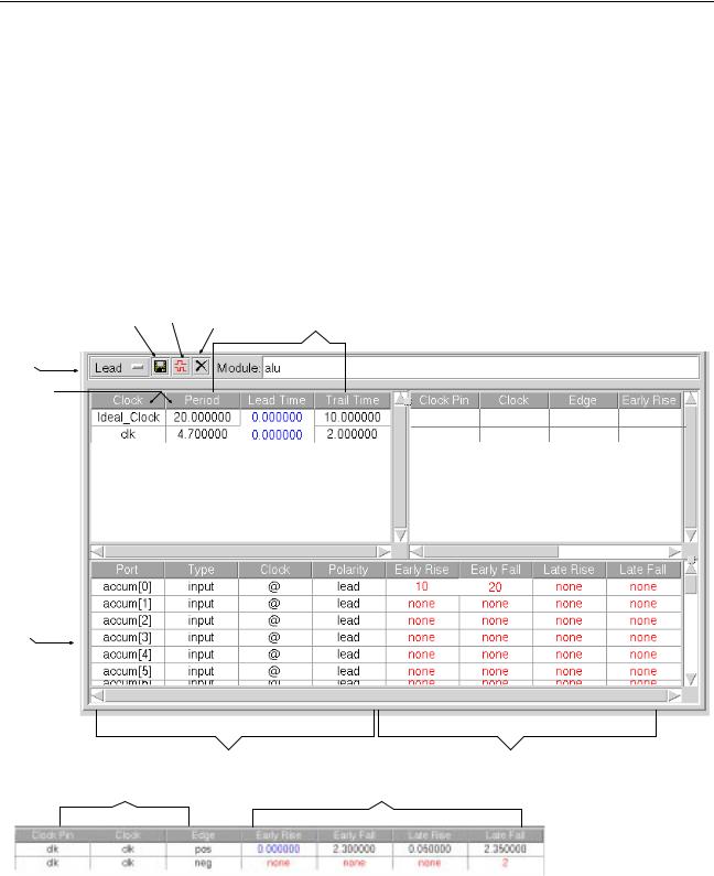
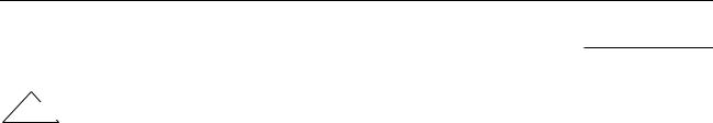
The constraints screen (a sample is shown in Figure 3-27) displays the current timing constraints and allows you to change data in the input fields. The constraints screen consists of three panels: ideal clock panel, port clock panel, and port constraints panel. The panels contain both editable input fields and uneditable data fields. The port clock panel has seven columns and is too wide to fully display in the figure below, therefore this panel is defined in the cutout at the bottom of the figure. On the actual screen, left click the scroll arrow under the panel to access all columns.
Figure 3-27 Sample Constraints Screen
Save Timing |
New Ideal |
Delete All |
input |
|
|
|
Clock |
|
|
|
|||
Assertions |
|
Constraints |
fields |
|
|
|
Polarity: |
|
|
|
|
|
|
Lead/Trail |
|
|
|
|
|
|
data |
|
|
|
|
|
|
fields |
|
|
|
|
|
|
|
|
|
ck |
ck |
pos |
0.000000 |
|
|
|
ck |
ck |
neg |
none |
Ideal Clock Panel |
Port Clock Panel |
|
(see cutout below) |
||
|
Port
Constraints
Panel
data |
input |
fields |
fields |
data |
input |
fields |
field |
Clock Port Panel Cutout
September 2000 |
84 |
Product Version 4.0 |

Ambit BuildGates Synthesis User Guide
Using the GUI
Note: If you begin typing in an input field and change your mind, press ESC to abort the process.
Clicking the right mouse button in any of the three panels displays a pop-up menu with additional functions. The following tables define the pop-up functions.
Table 3-28 Ideal Clock Panel Pop-Up Menu
Option |
Description |
|
|
Refresh Clock Table |
Update all three constraint panels with newly entered input. |
New Ideal Clock |
Create a new ideal clock. A dialog is displayed for entry of |
|
the clock name and period. |
|
|
Table 3-29 Port Clock Panel Pop-Up Menu
Option |
Description |
|
|
New Port Clock ... |
Create a port clock. A dialog is displayed for entry of the |
|
following information: ideal clock associated with the new |
|
port clock, name of port clock, positive or negative edge, |
|
and optionally, early or late rise and early or late fall. |
Remove Clock Assertions |
Remove all assertions associated with the selected port |
|
clock (this cannot be undone). |
|
|
Table 3-30 Port Constraints Panel Pop-Up Menu
Option |
Description |
|
|
Show Default Clock |
Display the data for the default ideal clock; this is indicated |
|
by the “@” symbol in the clock column of port constraints |
|
panel. |
Toggle Polarity |
Toggle between Lead and Trail in the polarity column of |
|
the port constraints panel. |
September 2000 |
85 |
Product Version 4.0 |

Ambit BuildGates Synthesis User Guide
Using the GUI
Table 3-30 Port Constraints Panel Pop-Up Menu, continued
Option |
Description |
|
|
Create Positive Edge Clock |
Create a positive edge clock for the selected port. |
|
You cannot have both a positive and negative edge clock. |
Create Negative Edge Clock |
Create a negative edge clock for the selected port. |
|
You cannot have both a positive and negative edge clock. |
Report Port Assertions |
Display a report on the assertions associated with the |
|
selected port. For each ideal clock, the report includes: |
|
input/output type, assertion status, early/late rise time, and |
|
early/late fall time. See Figure 3-28 for a sample port |
|
timing constraints report. |
Remove Port Assertions |
Remove all assertions associated with the selected port. A |
|
dialog box will ask for confirmation of the deletion. |
|
|
Figure 3-28 Sample Port Timing Constraints Report
After updating constraints, you can optimize the design by selecting Main Menu – Commands – Optimize, or generate a timing report by selecting Main Menu – Reports– Timing Report.
The values in the columns of all three panels are color-coded: red text indicates a “none” or missing entry, blue text indicates a zero value, and black text indicates values that you specified.
When the constraints tab is selected, the first constraint screen displayed contains the data for the default ideal clock, which is indicated by the “@” symbol in the clock column of port constraints panel. To display the port constraints data for an ideal clock listed on the ideal clock panel, left click the ideal clock name to update the port constraints panel.
To display the constraints screen such that it occupies the whole main screen window instead of only a portion of the window, place the cursor anywhere in the constraints screen and press the Control-m keys. Repeatedly pressing Control-m toggles between the standard splitscreen and the whole-screen display.
September 2000 |
86 |
Product Version 4.0 |
Ambit BuildGates Synthesis User Guide
Using the GUI
For additional information on the methodology of setting constraints, refer to Setting Timing Constraints in the Envisia Timing Analysis User Guide.
Important
To save all constraint and other changes made to your design, select Main Menu – File – Save and specify a file name before exiting Ambit BuildGates synthesis.
Changing Values in Input Fields
1.Click left mouse button in any panel input field that you want to change.
2.Type the new value (you do not need to erase the current value).
3.Press the Return key.
4.Click right mouse button anywhere in the port clock panel to display the pop-up menu for adding a port clock. See Adding a New Port Clock below for procedure.
5.Click right mouse button anywhere in the port constraints panel to display the pop-up menu for additional functions. See Changing Port Constraints below for procedure.
6.To save your changes, click left mouse button on the Save Timing Assertions icon on the constraints screen.
Adding an Ideal Clock
1.Click left mouse button on New Ideal Clock icon on the constraints screen.
2.In the dialog box that is displayed, enter the new clock name and period. Click Ok.
3.The new clock is added to the ideal clock panel.
4.To display and update the port constraints for the new clock, click left mouse button on the new ideal clock.
5.Set the constraints for the new ideal clock as described above in Changing Values in Input Fields.
Deleting Timing Constraints
1.Click left mouse button on Delete All Constraints icon on the constraints screen.
2.In the warning dialog that is displayed, click Ok to delete the constraints.
September 2000 |
87 |
Product Version 4.0 |