

 ATmega32(L)
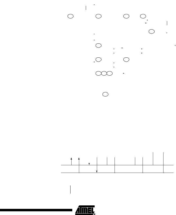
Figure 89. Formats and States in the Master Receiver Mode
MR
|
|
|
Successfull |
|
|
|
|
|
|
|
|
|
|
|
|
|
|
|
|
|
|
|
|
|
|
|
|
|
|
|
|
|
|
|
|
|
|
|
|
|
|
|
|
|
|
|
|
|
|
|
|
|
|
|
|
|
|
|
|
|
|
|
|
|
|
|
|
|
|
|
|
|
|
|
|
|
|
|
|
|
|
|
|
|
|
|
|
|
|
|
|
|
|
|
|
|
|
|
|
|
|
|
|
||
|
|
|
|
|
|
|
|
|
|
|
|
|
|
|
|
|
|
|
|
|
|
|
|
|
|
|
|
|
|
|
|
|
|
|
|
|
|
|
|
|
|
|
|
|
|
|
|
|
|
|
||
|
|
|
|
S |
|
SLA |
|
R |
|
A |
|
|
|
DATA |
|
|
|
A |
|
DATA |
|
|
|
|
|
|
|
|
|
P |
|
|
|
|
|
|
|
|
||||||||||||||
|
|
|
reception |
|
|
|
|
|
|
|
|
|
|
|
|
|
|
A |
|
|
|
|
|
|
|
|
|
|
|
|||||||||||||||||||||||
|
|
|
from a slave |
|
|
|
|
|
|
|
|
|
|
|
|
|
|
|
|
|
|
|
|
|
|
|
|
|
|
|
|
|
|
|
|
|
|
|
|
|
|
|
|
|
|
|
|
|
|
|
|
|
|
|
|
receiver |
|
|
|
|
|
|
|
|
|
|
|
|
|
|
|
|
|
|
|
|
|
|
|
|
|
|
|
|
|
|
|
|
|
|
|
|
|
|
|
|
|
|
|
|
|
|
|
||
|
|
|
|
|
|
|
|
|
|
|
|
|
|
|
|
|
|
|
|
|
|
|
|
|
|
|
|
|
|
|
|
|
|
|
|
|
|
|
|
|
|
|
|
|
|
|
|
|
|
|
|
|
|
|
|
|
|
|
$08 |
|
|
|
|
|
$40 |
|
|
|
|
|
|
|
|
$50 |
|
|
|
$58 |
|
|
|
|
|
|
|
|
|
|
|
|
|
|
|||||||||||||
|
|
|
Next transfer |
|
|
|
|
|
|
|
|
|
|
|
|
|
|
|
|
|
|
|
|
|
|
|
|
|
|
|
|
|
|
|
|
|
|
|
|
|
|
|
|
|
|
|
|
|
|
|
||
|
|
|
|
|
|
|
|
|
|
|
|
|
|
|
|
|
|
|
|
|
|
|
|
|
|
|
|
|
|
|
|
|
|
|
|
|
|
|
|
|
|
|
|
|
|
|
|
|
|
|||
|
|
|
|
|
|
|
|
|
|
|
|
|
|
|
|
|
|
|
|
|
|
|
|
|
|
|
|
|
|
|
|
|
|
|
|
|
|
|
RS |
SLA |
R |
|
||||||||||
|
|
|
started with a |
|
|
|
|
|
|
|
|
|
|
|
|
|
|
|
|
|
|
|
|
|
|
|
|
|
|
|
|
|
|
|
|
|
|
|
|
|
||||||||||||
|
|
|
repeated start |
|
|
|
|
|
|
|
|
|
|
|
|
|
|
|
|
|
|
|
|
|
|
|
|
|
|
|
|
|
|
|
|
|
|
|
|
|
|
|
|
|
|
|
|
|
|
|
||
|
|
|
condition |
|
|
|
|
|
|
|
|
|
|
|
|
|
|
|
|
|
|
|
|
|
|
|
|
|
|
|
|
|
|
|
|
|
|
|
|
|
|
|
|
|
|
|
|
|
|
|
||
|
|
|
|
|
|
|
|
|
|
|
|
|
|
|
|
|
|
|
|
|
|
|
|
|
|
|
|
|
|
|
|
|
|
|
|
|
|
|
|
|
|
|
|
|
|
|
|
|
|
|
|
|
|
|
|
|
|
|
|
|
|
|
|
|
|
|
|
|
|
|
|
|
|
|
|
|
|
|
|
|
|
|
|
|
|
|
|
|
|
|
|
|
|
$10 |
|
|
|
|
|
|
|
|
|||
|
|
|
|
|
|
|
|
|
|
|
|
|
|
|
|
|
|
|
|
|
|
|
|
|
|
|
|
|
|
|
|
|
|
|
|
|
|
|
|
|
|
|
|
|
|
|
|
|
|
|
|
|
|
|
|
Not acknowledge |
|
|
|
|
|
|
|
|
|
|
|
|
|
|
|
|
|
|
|
|
|
|
|
|
|
|
|
|
|
|
|
|
|
|
|
|
|
|
|
|
|
|
|
|
W |
|
|||
|
|
|
|
|
|
|
|
|
|
|
|
|
|
|
|
|
P |
|
|
|
|
|
|
|
|
|
|
|
|
|
|
|
|
|
|
|
|
|
|
|
|
|
|
|
|
|||||||
|
|
|
received after the |
|
|
|
|
|
|
|
|
A |
|
|
|
|
|
|
|
|
|
|
|
|
|
|
|
|
|
|
|
|
|
|
|
|
|
|
|
|
|
|
|
|
|
|
|
|||||
|
|
|
|
|
|
|
|
|
|
|
|
|
|
|
|
|
|
|
|
|
|
|
|
|
|
|
|
|
|
|
|
|
|
|
|
|
|
|
|
|
|
|
||||||||||
|
|
|
slave address |
|
|
|
|
|
|
|
|
|
|
|
|
|
|
|
|
|
|
|
|
|
|
|
|
|
|
|
|
|
|
|
|
|
|
|
|
|
|
|
|
|
|
|
|
|
|
|
||
|
|
|
|
|
|
|
|
|
|
|
|
|
|
|
|
|
|
|
|
|
|
|
|
|
|
|
|
|
|
|
|
|
|
|
|
|
|
|
|
|
|
|
|
|
|
|
|
|
|
|
|
|
|
|
|
|
|
|
|
|
|
|
|
|
|
$48 |
|
|
|
|
|
|
|
|
|
|
|
|
|
|
|
|
|
|
|
|
|
|
|
|
|
|
|
|
|
|
|
|
|
|
|
||||
|
|
|
Arbitration lost in slave |
|
|
|
|
|
|
|
|
|
|
|
|
|
|
|
|
|
|
|
|
|
|
|
|
|
|
|
|
|
|
|
|
|
|
|
|
|
|
|
|
MT |
||||||||
|
|
|
|
|
|
|
|
|
|
|
|
|
|
|
|
|
|
|
|
|
|
|
|
|
|
|
|
|
|
|
|
|
|
|
|
|
|
|
|
|
|
|
|
|
|
|
|
|||||
|
|
|
|
|
|
|
|
|
|
|
|
|
|
|
|
|
|
|
|
|
|
|
|
|
|
|
|
|
|
|
|
|
|
|
|
|
|
|
|
|
|
|
|
|
|
|
||||||
|
|
|
|
|
|
|
|
|
|
|
|
|
|
|
|
Other master |
|
|
|
|
|
|
Other master |
|
|
|
|
|
|
|
|
|
|
|
|
|
|
|
|
|
|
|
||||||||||
|
|
|
address or data byte |
|
|
|
|
|
|
|
A or A |
|
|
continues |
|
|
|
|
A |
|
continues |
|
|
|
|
|
|
|
|
|
|
|
|
|
|
|
|
|
|
|
||||||||||||
|
|
|
|
|
|
|
|
|
|
|
|
|
|
|
|
|
|
|
|
|
|
|
|
|
|
|
|
|
|
|
|
|
|
|
|
|
|
|
|
|
|
|
|
|
|
|
|
|
|
|
||
|
|
|
|
|
|
|
|
|
|
|
|
|
$38 |
|
|
|
|
|
|
|
$38 |
|
|
|
|
|
|
|
|
|
|
|
|
|
|
|
|
|
|
|
|
|
|
|||||||||
|
|
|
Arbitration lost and |
|
|
|
|
|
|
|
|
|
|
|
|
|
|
|
|
|
|
|
|
|
|
|
|
|
|
|
|
|
|
|
|
|
|
|
|
|
|
|
|
|
|
|
|
|
|
|||
|
|
|
|
|
|
|
|
|
|
|
|
|
|
|
|
|
|
|
|
|
|
|
|
|
|
|
|
|
|
|
|
|
|
|
|
|
|
|
|
|
|
|
|
|
|
|
|
|
||||
|
|
|
|
|
|
|
|
|
|
|
A |
|
Other master |
|
|
|
|
|
|
|
|
|
|
|
|
|
|
|
|
|
|
|
|
|
|
|
|
|
|
|
|
|||||||||||
|
|
|
addressed as slave |
|
|
|
|
|
|
|
|
|
|
continues |
|
|
|
|
|
|
|
|
|
|
|
|
|
|
|
|
|
|
|
|
|
|
|
|
|
|
|
|
||||||||||
|
|
|
|
|
|
|
|
|
|
|
|
|
|
|
|
|
|
|
|
|
|
|
|
|
|
|
To corresponding |
|
|
|
|
|
|
|
|
|
|
|
|
|
|
|
|
|
|
|
||||||
|
|
|
|
|
|
|
|
|
|
|
|
|
$68 |
$78 $B0 |
|
|
|
|
|
|
|
|
|
|
|
|
|
|
|
|
|
|
|
|
|
|
|
|||||||||||||||
|
|
|
|
|
|
|
|
|
|
|
|
|
|
|
|
states in slave mode |
|
|
|
|
|
|
|
|
|
|
|
|
|
|
|
|
|
|
|
|||||||||||||||||
|
|
|
|
|
|
|
|
|
|
|
|
|
|
|
|
|
|
|
|
|
|
|
|
|
|
|
|
|
|
|
|
|
|
|
|
|
|
|
|
|
|
|
|
|
|
|
|
|||||
|
|
|
|
|
|
|
|
|
|
|
|
|
|
|
|
|
|
|
|
|
|
|
|
|
Any number of data bytes |
|
|
|
|
|
|
|
|
|
|
|
|
|
|
|
|
|
|
|
||||||||
|
|
|
|
From master to slave |
|
|
DATA |
|
|
|
|
A |
|
|
|
|
|
|
|
|
|
|
|
|
|
|
|
|
|
|
|
|||||||||||||||||||||
|
|
|
|
|
|
|
|
|
|
and their associated acknowledge bits |
|
|
|
|
|
|
|
|
|
|
|
|
||||||||||||||||||||||||||||||
|
|
|
|
From slave to master |
|
|
|
|
|
|
|
|
|
n |
This number (contained in TWSR) corresponds |
|
|
|
|
|
|
|
|
|||||||||||||||||||||||||||||
|
|
|
|
|
|
|
|
|
|
|
|
|
|
|
|
|
|
|
|
|
||||||||||||||||||||||||||||||||
|
|
|
|
|
|
|
|
|
|
|
|
|
|
|
|
|
|
|
|
to a defined state of the Two-wire Serial Bus. The |
|
|
|
|
|
|
|
|
||||||||||||||||||||||||
|
|
|
|
|
|
|
|
|
|
|
|
|
|
|
|
|
|
|
|
|
|
|
|
|
|
|
||||||||||||||||||||||||||
|
|
|
|
|
|
|
|
|
|
|
|
|
|
|
|
|
|
|
|
|
|
|
|
|
prescaler bits are zero or masked to zero |
|
|
|
|
|
|
|
|
|
|
|
|
|||||||||||||||
Slave Receiver Mode |
In the Slave Receiver mode, a number of data bytes are received from a master trans- |
|||||||||||||||||||||||||||||||||||||||||||||||||||
|
mitter (see Figure 90). All the status codes mentioned in this section assume that the |
|||||||||||||||||||||||||||||||||||||||||||||||||||
|
prescaler bits are zero or are masked to zero. |
|
|
|
|
|
|
|
|
|
|
|
|
|
|
|
|
|
|
|
|
|
|
|
|
|
|
|
|
|||||||||||||||||||||||
|
Figure 90. Data Transfer in Slave Receiver Mode |
|
|
|
|
|
|
|
|
|
|
|
|
|
|
|
|
|
|
|
|
|
|
|||||||||||||||||||||||||||||
|
|
|
|
|
|
|
|
|
|
|
|
|
|
|
|
|
|
|
|
|
|
|
|
|
|
|
|
|
|
|
|
|
|
VCC |
|
|
|
|
|
|
|
|
|
|
|
|
||||||
|
|
|
|
|
|
|
|
|
|
|
|
|
|
|
|
|
|
|
|
|
|
|
|
|
|
|
|
|
|
|
|
|
|
|
|
|
|
|
|
|
|
|
|
|
|
|||||||
|
|
|
|
|
|
|
|
|
|
|
|
|
|
|
|
|
|
|
|
|
|
|
|
|
|
|
|
|
|
|
|
|
|
|
|
|
|
|
|
|
|
|
|
|
|
|
||||||
|
|
|
|
|
|
|
Device 1 |
|
|
Device 2 |
|
|
|
Device 3 |
........ |
|
|
|
|
|
|
|
|
|
|
|
|
|
|
|
|
|
|
|
|
|
|
|||||||||||||||
|
|
|
|
|
|
|
|
|
|
|
|
|
Device n |
|
|
|
|
R1 |
|
|
R2 |
|
|
|
|
|||||||||||||||||||||||||||
|
|
|
|
|
|
|
|
SLAVE |
|
|
MASTER |
|
|
|
|
|
|
|
|
|
|
|
|
|
||||||||||||||||||||||||||||
|
|
|
|
|
|
|
RECEIVER |
|
TRANSMITTER |
|
|
|
|
|
|
|
|
|
|
|
|
|
|
|
|
|
|
|
|
|
|
|
|
|
|
|
|
|
|
|
|
|
|
|
|
|||||||
|
|
|
|
|
|
|
|
|
|
|
|
|
|
|
|
|
|
|
|
|
|
|
|
|
|
|
|
|
|
|
|
|
|
|
|
|
|
|
|
|
|
|
|
|
|
|
|
|
|
|
|
|
|
|
|
|
|
|
|
|
|
|
|
|
|
|
|
|
|
|
|
|
|
|
|
|
|
|
|
|
|
|
|
|
|
|
|
|
|
|
|
|
|
|
|
|
|
|
|
|
|
|
|
|
|
|
|
|
|
|
|
|
|
|
|
|
|
|
|
|
|
|
|
|
|
|
|
|
|
|
|
|
|
|
|
|
|
|
|
|
|
|
|
|
|
|
|
|
|
|
|
|
|
|
|
|
|
|
SDA
SCL
To initiate the Slave Receiver mode, TWAR and TWCR must be initialized as follows:
TWAR |
TWA6 |
TWA5 |
TWA4 |
TWA3 |
TWA2 |
TWA1 |
TWA0 |
TWGCE |
|
|
|
|
|
|
|
|
|
Value |
|
|
Device’s Own Slave Address |
|
|
|
||
|
|
|
|
|
|
|
|
|
187
2503F–AVR–12/03

The upper seven bits are the address to which the Two-wire Serial Interface will respond when addressed by a master. If the LSB is set, the TWI will respond to the general call address ($00), otherwise it will ignore the general call address.
TWCR |
TWINT |
TWEA |
TWSTA |
TWSTO |
TWWC |
TWEN |
– |
TWIE |
Value |
0 |
1 |
0 |
0 |
0 |
1 |
0 |
X |
|
|
|
|
|
|
|
|
|
TWEN must be written to one to enable the TWI. The TWEA bit must be written to one to enable the acknowledgement of the device’s own slave address or the general call address. TWSTA and TWSTO must be written to zero.
When TWAR and TWCR have been initialized, the TWI waits until it is addressed by its own slave address (or the general call address if enabled) followed by the data direction bit. If the direction bit is “0” (write), the TWI will operate in SR mode, otherwise ST mode is entered. After its own slave address and the write bit have been received, the TWINT Flag is set and a valid status code can be read from TWSR. The status code is used to determine the appropriate software action. The appropriate action to be taken for each status code is detailed in Table 76. The Slave Receiver mode may also be entered if arbitration is lost while the TWI is in the Master mode (see states $68 and $78).
If the TWEA bit is reset during a transfer, the TWI will return a “Not Acknowledge” (“1”) to SDA after the next received data byte. This can be used to indicate that the slave is not able to receive any more bytes. While TWEA is zero, the TWI does not acknowledge its own slave address. However, the Two-wire Serial Bus is still monitored and address recognition may resume at any time by setting TWEA. This implies that the TWEA bit may be used to temporarily isolate the TWI from the Two-wire Serial Bus.
In all sleep modes other than Idle Mode, the clock system to the TWI is turned off. If the TWEA bit is set, the interface can still acknowledge its own slave address or the general call address by using the Two-wire Serial Bus clock as a clock source. The part will then wake up from sleep and the TWI will hold the SCL clock low during the wake up and until the TWINT Flag is cleared (by writing it to one). Further data reception will be carried out as normal, with the AVR clocks running as normal. Observe that if the AVR is set up with a long start-up time, the SCL line may be held low for a long time, blocking other data transmissions.
Note that the Two-wire Serial Interface Data Register – TWDR does not reflect the last byte present on the bus when waking up from these sleep modes.
188 ATmega32(L)
2503F–AVR–12/03

ATmega32(L)
Table 76. Status Codes for Slave Receiver Mode
Status Code |
|
|
Application Software Response |
|
|
|||
(TWSR) |
Status of the Two-wire Serial Bus |
|
|
To TWCR |
|
|
||
Prescaler Bits |
and Two-wire Serial |
Interface |
|
|
|
|
||
To/from TWDR |
STA |
STO |
TWINT |
TWEA |
|
|||
are 0 |
Hardware |
|
Next Action Taken by TWI Hardware |
|||||
|
|
|||||||
|
|
|
|
|
|
|||
$60 |
Own SLA+W has been received; |
No TWDR action or |
X |
0 |
1 |
0 |
Data byte will be received and NOT ACK will be |
|
|
ACK has been returned |
|
|
|
|
|
|
returned |
|
|
|
No TWDR action |
X |
0 |
1 |
1 |
Data byte will be received and ACK will be returned |
$68 |
Arbitration lost in SLA+R/W as |
No TWDR action or |
X |
0 |
1 |
0 |
Data byte will be received and NOT ACK will be |
|
|
master; own SLA+W has been |
|
|
|
|
|
returned |
|
|
received; ACK has been returned |
No TWDR action |
X |
0 |
1 |
1 |
Data byte will be received and ACK will be returned |
|
$70 |
General call address has been |
No TWDR action or |
X |
0 |
1 |
0 |
Data byte will be received and NOT ACK will be |
|
|
received; ACK has been returned |
|
|
|
|
|
returned |
|
|
|
|
No TWDR action |
X |
0 |
1 |
1 |
Data byte will be received and ACK will be returned |
$78 |
Arbitration lost in SLA+R/W as |
No TWDR action or |
X |
0 |
1 |
0 |
Data byte will be received and NOT ACK will be |
|
|
master; General call address has |
|
|
|
|
|
returned |
|
|
been received; ACK has been |
No TWDR action |
X |
0 |
1 |
1 |
Data byte will be received and ACK will be returned |
|
|
returned |
|
|
|
|
|
|
|
$80 |
Previously addressed |
with own |
Read data byte or |
X |
0 |
1 |
0 |
Data byte will be received and NOT ACK will be |
|
SLA+W; data has been received; |
|
|
|
|
|
returned |
|
|
ACK has been returned |
|
Read data byte |
X |
0 |
1 |
1 |
Data byte will be received and ACK will be returned |
$88 |
Previously addressed |
with own |
Read data byte or |
0 |
0 |
1 |
0 |
Switched to the not addressed Slave mode; |
|
SLA+W; data has been received; |
|
|
|
|
|
no recognition of own SLA or GCA |
|
|
NOT ACK has been returned |
Read data byte or |
0 |
0 |
1 |
1 |
Switched to the not addressed Slave mode; |
|
|
|
|
|
|
|
|
|
own SLA will be recognized; |
|
|
|
|
|
|
|
|
GCA will be recognized if TWGCE = “1” |
|
|
|
Read data byte or |
1 |
0 |
1 |
0 |
Switched to the not addressed Slave mode; |
|
|
|
|
|
|
|
|
no recognition of own SLA or GCA; |
|
|
|
|
|
|
|
|
a START condition will be transmitted when the bus |
|
|
|
|
|
|
|
|
becomes free |
|
|
|
Read data byte |
1 |
0 |
1 |
1 |
Switched to the not addressed Slave mode; |
|
|
|
|
|
|
|
|
own SLA will be recognized; |
|
|
|
|
|
|
|
|
GCA will be recognized if TWGCE = “1”; |
|
|
|
|
|
|
|
|
a START condition will be transmitted when the bus |
|
|
|
|
|
|
|
|
becomes free |
$90 |
Previously addressed with |
Read data byte or |
X |
0 |
1 |
0 |
Data byte will be received and NOT ACK will be |
|
|
general call; data has been re- |
|
|
|
|
|
returned |
|
|
ceived; ACK has been returned |
Read data byte |
X |
0 |
1 |
1 |
Data byte will be received and ACK will be returned |
|
$98 |
Previously addressed with |
Read data byte or |
0 |
0 |
1 |
0 |
Switched to the not addressed Slave mode; |
|
|
general call; data has been |
|
|
|
|
|
no recognition of own SLA or GCA |
|
|
received; NOT ACK has been |
Read data byte or |
0 |
0 |
1 |
1 |
Switched to the not addressed Slave mode; |
|
|
returned |
|
|
|
|
|
|
own SLA will be recognized; |
|
|
|
|
|
|
|
|
GCA will be recognized if TWGCE = “1” |
|
|
|
Read data byte or |
1 |
0 |
1 |
0 |
Switched to the not addressed Slave mode; |
|
|
|
|
|
|
|
|
no recognition of own SLA or GCA; |
|
|
|
|
|
|
|
|
a START condition will be transmitted when the bus |
|
|
|
|
|
|
|
|
becomes free |
|
|
|
Read data byte |
1 |
0 |
1 |
1 |
Switched to the not addressed Slave mode; |
|
|
|
|
|
|
|
|
own SLA will be recognized; |
|
|
|
|
|
|
|
|
GCA will be recognized if TWGCE = “1”; |
|
|
|
|
|
|
|
|
a START condition will be transmitted when the bus |
|
|
|
|
|
|
|
|
becomes free |
$A0 |
A STOP condition or repeated |
No action |
0 |
0 |
1 |
0 |
Switched to the not addressed Slave mode; |
|
|
START condition has been |
|
|
|
|
|
no recognition of own SLA or GCA |
|
|
received while still addressed as |
|
0 |
0 |
1 |
1 |
Switched to the not addressed Slave mode; |
|
|
slave |
|
|
|
|
|
|
own SLA will be recognized; |
|
|
|
|
|
|
|
|
GCA will be recognized if TWGCE = “1” |
|
|
|
|
1 |
0 |
1 |
0 |
Switched to the not addressed Slave mode; |
|
|
|
|
|
|
|
|
no recognition of own SLA or GCA; |
|
|
|
|
|
|
|
|
a START condition will be transmitted when the bus |
|
|
|
|
|
|
|
|
becomes free |
|
|
|
|
1 |
0 |
1 |
1 |
Switched to the not addressed Slave mode; |
|
|
|
|
|
|
|
|
own SLA will be recognized; |
|
|
|
|
|
|
|
|
GCA will be recognized if TWGCE = “1”; |
|
|
|
|
|
|
|
|
a START condition will be transmitted when the bus |
|
|
|
|
|
|
|
|
becomes free |
189
2503F–AVR–12/03
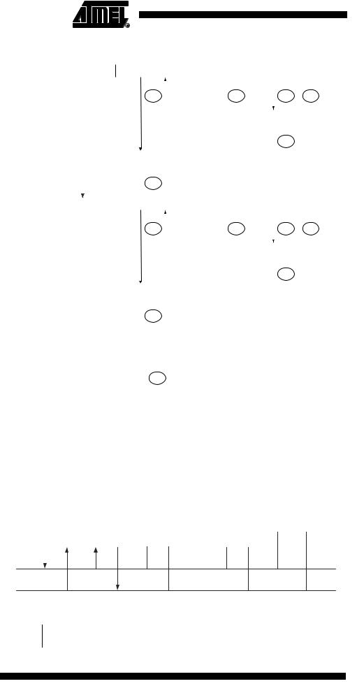
Figure 91. Formats and States in the Slave Receiver Mode
|
Reception of the own |
|
S |
SLA |
W |
|
A |
|
DATA |
A |
|
DATA |
|
|
A |
|
P or S |
|
|||||||
|
slave address and one or |
|
|
|
|
|
|
|
|
||||||||||||||||
|
more data bytes. All are |
|
|
|
|
|
|
|
|
|
|
|
|
|
|
|
|
|
|
|
|
|
|
|
|
|
acknowledged |
|
|
|
|
|
|
|
|
|
|
|
|
|
|
|
|
|
|
|
|
|
|
||
|
|
|
|
|
|
|
|
|
|
|
|
|
|
|
|
|
|
|
|
|
|
|
|
|
|
|
|
|
|
|
|
|
|
$60 |
|
|
|
$80 |
|
|
|
$80 |
|
$A0 |
|
||||||
|
Last data byte received |
|
|
|
|
|
|
|
|
|
|
|
|
|
|
|
|
|
|
|
|
|
|
||
|
|
|
|
|
|
|
|
|
|
|
|
|
|
|
|
|
|
|
|
|
|
|
|||
|
|
|
|
|
|
|
|
|
|
|
|
|
|
|
|
|
|
|
|
P or S |
|
||||
|
is not acknowledged |
|
|
|
|
|
|
|
|
|
|
|
|
|
|
|
A |
|
|
|
|||||
|
|
|
|
|
|
|
|
|
|
|
|
|
|
|
|
|
|
|
|
|
|
|
|
|
|
|
|
|
|
|
|
|
|
|
|
|
|
|
|
|
|
|
|
$88 |
|
|
|
|
|||
|
Arbitration lost as master |
|
|
|
|
|
|
|
|
|
|
|
|
|
|
|
|
|
|
|
|
|
|
||
|
|
|
|
|
A |
|
|
|
|
|
|
|
|
|
|
|
|
|
|
|
|
||||
|
and addressed as slave |
|
|
|
|
|
|
|
|
|
|
|
|
|
|
|
|
|
|
|
|
||||
|
|
|
|
|
|
|
|
|
|
|
|
|
|
|
|
|
|
|
|
|
|
|
|
|
|
|
|
|
|
|
|
|
|
|
|
|
|
|
|
|
|
|
|
|
|
|
|
|
|
|
|
|
|
|
|
|
|
|
|
$68 |
|
|
|
|
|
|
|
|
|
|
|
|
|
|
|
|
|
|
Reception of the general call |
|
|
|
|
|
|
|
|
|
|
|
|
|
|
|
|
|
|
|
|
|
|
||
|
|
|
|
|
|
|
|
|
|
|
|
|
|
|
|
|
|
|
|
|
|
|
|||
|
|
General Call |
|
A |
|
DATA |
A |
|
DATA |
|
|
A |
|
P or S |
|
||||||||||
|
address and one or more data |
|
|
|
|
|
|
|
|
||||||||||||||||
|
bytes |
|
|
|
|
|
|
|
|
|
|
|
|
|
|
|
|
|
|
|
|
|
|
||
|
|
|
|
|
|
|
|
|
|
|
|
|
|
|
|
|
|
|
|
|
|
|
|
|
|
|
|
|
|
|
|
|
|
$70 |
|
|
|
$90 |
|
|
|
$90 |
|
$A0 |
|
||||||
|
Last data byte received is |
|
|
|
|
|
|
|
|
|
|
|
|
|
|
|
|
|
|
|
|
|
|
||
|
|
|
|
|
|
|
|
|
|
|
|
|
|
|
|
|
|
|
|
|
|
|
|||
|
|
|
|
|
|
|
|
|
|
|
|
|
|
|
|
|
|
|
|
P or S |
|
||||
|
not acknowledged |
|
|
|
|
|
|
|
|
|
|
|
|
|
|
|
A |
|
|
|
|||||
|
|
|
|
|
|
|
|
|
|
|
|
|
|
|
|
|
|
|
|
|
|
|
|
|
|
|
|
|
|
|
|
|
|
|
|
|
|
|
|
|
|
|
|
$98 |
|
|
|
|
|||
|
Arbitration lost as master and |
|
|
|
|
|
|
|
|
|
|
|
|
|
|
|
|
|
|
|
|
|
|
||
|
|
|
|
|
A |
|
|
|
|
|
|
|
|
|
|
|
|
|
|
|
|
||||
|
addressed as slave by general call |
|
|
|
|
|
|
|
|
|
|
|
|
|
|
|
|
|
|
|
|||||
|
|
|
|
|
|
|
|
|
|
|
|
|
|
|
|
|
|
|
|
|
|
|
|
|
|
|
|
|
|
|
|
|
|
|
|
|
|
|
|
|
|
|
|
|
|
|
|
|
|
|
|
|
|
|
|
|
|
|
|
$78 |
|
|
|
|
|
|
|
|
|
|
|
|
|
|
|
|
|
|
|
|
|
|
|
|
|
|
|
|
|
|
|
|
|
|
|
|
|
|
|
|
|||
|
|
|
|
|
|
|
|
|
|
|
|
Any number of data bytes |
|
|
|
|
|
|
|
|
|
|
|||
|
|
From master to slave |
|
DATA |
|
|
A |
|
|
|
|
|
|
|
|
|
|
|
|||||||
|
|
|
|
|
|
and their associated acknowledge bits |
|
|
|
|
|
|
|
|
|||||||||||
|
|
From slave to master |
|
|
|
|
n |
|
|
This number (contained in TWSR) corresponds |
|
|
|
||||||||||||
|
|
|
|
|
|
|
|
|
|
|
|||||||||||||||
|
|
|
|
|
|
|
|
|
|
|
to a defined state of the Two-wire Serial Bus. The |
|
|
|
|||||||||||
|
|
|
|
|
|
|
|
|
|
|
|
|
|||||||||||||
|
|
|
|
|
|
|
|
|
|
|
|
prescaler bits are zero or masked to zero |
|
|
|
||||||||||
Slave Transmitter Mode |
In the Slave Transmitter mode, a number of data bytes are transmitted to a master |
|
receiver (see Figure 92). All the status codes mentioned in this section assume that the |
|
prescaler bits are zero or are masked to zero. |
|
Figure 92. Data Transfer in Slave Transmitter Mode |
|
|
|
|
|
|
|
VCC |
|
|
|
|
|
|
|
|
|
|
|
|
|
|
|
|
|
|
|
|
|
|
|
|
|
|
|
|
|
|
|
|
|
|
|
|
|
|
|
|
Device 1 |
|
Device 2 |
|
Device 3 |
........ |
|
|
|
|
|
|
|
|
|
|
|
|
Device n |
|
|
R1 |
|
R2 |
|
|||||||
|
SLAVE |
|
MASTER |
|
|
|
|
|
|||||||
TRANSMITTER |
|
RECEIVER |
|
|
|
|
|
|
|
|
|
|
|
|
|
|
|
|
|
|
|
|
|
|
|
|
|
|
|
|
|
|
|
|
|
|
|
|
|
|
|
|
|
|
|
|
|
|
|
|
|
|
|
|
|
|
|
|
|
|
|
|
|
SDA
SCL
To initiate the Slave Transmitter mode, TWAR and TWCR must be initialized as follows:
TWAR |
TWA6 |
TWA5 |
TWA4 |
TWA3 |
TWA2 |
TWA1 |
TWA0 |
TWGCE |
|
|
|
|
|
|
|
|
|
Value |
|
|
Device’s Own Slave Address |
|
|
|
||
|
|
|
|
|
|
|
|
|
190 ATmega32(L)
2503F–AVR–12/03
 ATmega32(L)
The upper seven bits are the address to which the Two-wire Serial Interface will respond when addressed by a master. If the LSB is set, the TWI will respond to the general call address ($00), otherwise it will ignore the general call address.
TWCR |
TWINT |
TWEA |
TWSTA |
TWSTO |
TWWC |
TWEN |
– |
TWIE |
Value |
0 |
1 |
0 |
0 |
0 |
1 |
0 |
X |
|
|
|
|
|
|
|
|
|
TWEN must be written to one to enable the TWI. The TWEA bit must be written to one to enable the acknowledgement of the device’s own slave address or the general call address. TWSTA and TWSTO must be written to zero.
When TWAR and TWCR have been initialized, the TWI waits until it is addressed by its own slave address (or the general call address if enabled) followed by the data direction bit. If the direction bit is “1” (read), the TWI will operate in ST mode, otherwise SR mode is entered. After its own slave address and the write bit have been received, the TWINT Flag is set and a valid status code can be read from TWSR. The status code is used to determine the appropriate software action. The appropriate action to be taken for each status code is detailed in Table 77. The slave transmitter mode may also be entered if arbitration is lost while the TWI is in the Master mode (see state $B0).
If the TWEA bit is written to zero during a transfer, the TWI will transmit the last byte of the transfer. State $C0 or state $C8 will be entered, depending on whether the master receiver transmits a NACK or ACK after the final byte. The TWI is switched to the not addressed Slave mode, and will ignore the master if it continues the transfer. Thus the master receiver receives all “1” as serial data. State $C8 is entered if the master demands additional data bytes (by transmitting ACK), even though the slave has transmitted the last byte (TWEA zero and expecting NACK from the master).
While TWEA is zero, the TWI does not respond to its own slave address. However, the Two-wire Serial Bus is still monitored and address recognition may resume at any time by setting TWEA. This implies that the TWEA bit may be used to temporarily isolate the TWI from the Two-wire Serial Bus.
In all sleep modes other than Idle mode, the clock system to the TWI is turned off. If the TWEA bit is set, the interface can still acknowledge its own slave address or the general call address by using the Two-wire Serial Bus clock as a clock source. The part will then wake up from sleep and the TWI will hold the SCL clock will low during the wake up and until the TWINT Flag is cleared (by writing it to one). Further data transmission will be carried out as normal, with the AVR clocks running as normal. Observe that if the AVR is set up with a long start-up time, the SCL line may be held low for a long time, blocking other data transmissions.
Note that the Two-wire Serial Interface Data Register – TWDR does not reflect the last byte present on the bus when waking up from these sleep modes.
191
2503F–AVR–12/03

Table 77. Status Codes for Slave Transmitter Mode
Status Code |
|
Application Software Response |
|
|
||||
(TWSR) |
Status of the Two-wire Serial Bus |
|
|
To TWCR |
|
|
||
Prescaler Bits |
and Two-wire Serial Interface |
|
|
|
|
|||
To/from TWDR |
STA |
STO |
TWINT |
TWEA |
|
|||
are 0 |
Hardware |
Next Action Taken by TWI Hardware |
||||||
|
||||||||
|
|
|
|
|
||||
$A8 |
Own SLA+R has been received; |
Load data byte or |
X |
0 |
1 |
0 |
Last data byte will be transmitted and NOT ACK should |
|
|
ACK has been returned |
|
|
|
|
|
be received |
|
|
|
Load data byte |
X |
0 |
1 |
1 |
Data byte will be transmitted and ACK should be re- |
|
|
|
|
|
|
|
|
ceived |
|
$B0 |
Arbitration lost in SLA+R/W as |
Load data byte or |
X |
0 |
1 |
0 |
Last data byte will be transmitted and NOT ACK should |
|
|
master; own SLA+R has been |
|
|
|
|
|
be received |
|
|
received; ACK has been returned |
Load data byte |
X |
0 |
1 |
1 |
Data byte will be transmitted and ACK should be re- |
|
|
|
|
|
|
|
|
ceived |
|
$B8 |
Data byte in TWDR has been |
Load data byte or |
X |
0 |
1 |
0 |
Last data byte will be transmitted and NOT ACK should |
|
|
transmitted; ACK has been |
|
|
|
|
|
be received |
|
|
received |
Load data byte |
X |
0 |
1 |
1 |
Data byte will be transmitted and ACK should be re- |
|
|
|
|
|
|
|
|
ceived |
|
$C0 |
Data byte in TWDR has been |
No TWDR action or |
0 |
0 |
1 |
0 |
Switched to the not addressed Slave mode; |
|
|
transmitted; NOT ACK has been |
|
|
|
|
|
no recognition of own SLA or GCA |
|
|
received |
No TWDR action or |
0 |
0 |
1 |
1 |
Switched to the not addressed Slave mode; |
|
|
|
|
|
|
|
|
own SLA will be recognized; |
|
|
|
|
|
|
|
|
GCA will be recognized if TWGCE = “1” |
|
|
|
No TWDR action or |
1 |
0 |
1 |
0 |
Switched to the not addressed Slave mode; |
|
|
|
|
|
|
|
|
no recognition of own SLA or GCA; |
|
|
|
|
|
|
|
|
a START condition will be transmitted when the bus |
|
|
|
|
|
|
|
|
becomes free |
|
|
|
No TWDR action |
1 |
0 |
1 |
1 |
Switched to the not addressed Slave mode; |
|
|
|
|
|
|
|
|
own SLA will be recognized; |
|
|
|
|
|
|
|
|
GCA will be recognized if TWGCE = “1”; |
|
|
|
|
|
|
|
|
a START condition will be transmitted when the bus |
|
|
|
|
|
|
|
|
becomes free |
|
$C8 |
Last data byte in TWDR has been |
No TWDR action or |
0 |
0 |
1 |
0 |
Switched to the not addressed Slave mode; |
|
|
transmitted (TWEA = “0”); ACK |
|
|
|
|
|
no recognition of own SLA or GCA |
|
|
has been received |
No TWDR action or |
0 |
0 |
1 |
1 |
Switched to the not addressed Slave mode; |
|
|
|
|
|
|
|
|
own SLA will be recognized; |
|
|
|
|
|
|
|
|
GCA will be recognized if TWGCE = “1” |
|
|
|
No TWDR action or |
1 |
0 |
1 |
0 |
Switched to the not addressed Slave mode; |
|
|
|
|
|
|
|
|
no recognition of own SLA or GCA; |
|
|
|
|
|
|
|
|
a START condition will be transmitted when the bus |
|
|
|
|
|
|
|
|
becomes free |
|
|
|
No TWDR action |
1 |
0 |
1 |
1 |
Switched to the not addressed Slave mode; |
|
|
|
|
|
|
|
|
own SLA will be recognized; |
|
|
|
|
|
|
|
|
GCA will be recognized if TWGCE = “1”; |
|
|
|
|
|
|
|
|
a START condition will be transmitted when the bus |
|
|
|
|
|
|
|
|
becomes free |
|
192 ATmega32(L)
2503F–AVR–12/03