

ATmega32(L)
Transmission Modes The TWI can operate in one of four major modes. These are named Master Transmitter (MT), Master Receiver (MR), Slave Transmitter (ST) and Slave Receiver (SR). Several of these modes can be used in the same application. As an example, the TWI can use MT mode to write data into a TWI EEPROM, MR mode to read the data back from the EEPROM. If other masters are present in the system, some of these might transmit data to the TWI, and then SR mode would be used. It is the application software that decides which modes are legal.
The following sections describe each of these modes. Possible status codes are described along with figures detailing data transmission in each of the modes. These figures contain the following abbreviations:
S: START condition
Rs: REPEATED START condition
R: Read bit (high level at SDA)
W: Write bit (low level at SDA)
A: Acknowledge bit (low level at SDA)
A: Not acknowledge bit (high level at SDA)
Data: 8-bit data byte
P: STOP condition
SLA: Slave Address
In Figure 87 to Figure 93, circles are used to indicate that the TWINT Flag is set. The numbers in the circles show the status code held in TWSR, with the prescaler bits masked to zero. At these points, actions must be taken by the application to continue or complete the TWI transfer. The TWI transfer is suspended until the TWINT Flag is cleared by software.
When the TWINT Flag is set, the status code in TWSR is used to determine the appropriate software action. For each status code, the required software action and details of the following serial transfer are given in Table 74 to Table 77. Note that the prescaler bits are masked to zero in these tables.
Master Transmitter Mode In the Master Transmitter mode, a number of data bytes are transmitted to a slave receiver (see Figure 86). In order to enter a Master mode, a START condition must be transmitted. The format of the following address packet determines whether Master Transmitter or Master Receiver mode is to be entered. If SLA+W is transmitted, MT mode is entered, if SLA+R is transmitted, MR mode is entered. All the status codes mentioned in this section assume that the prescaler bits are zero or are masked to zero.
181
2503F–AVR–12/03
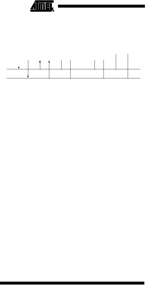
Figure 86. Data Transfer in Master Transmitter Mode
|
|
|
|
|
|
|
VCC |
|
|
|
|
|
|
|
|
|
|
|
|
|
|
|
|
|
|
|
|
|
|
|
|
|
|
|
|
|
|
|
|
|
|
|
|
|
|
|
|
Device 1 |
|
Device 2 |
|
Device 3 |
........ |
|
|
|
|
|
|
|
|
|
|
|
|
Device n |
|
|
R1 |
|
R2 |
|
|||||||
|
MASTER |
|
SLAVE |
|
|
|
|
|
|||||||
TRANSMITTER |
|
RECEIVER |
|
|
|
|
|
|
|
|
|
|
|
|
|
|
|
|
|
|
|
|
|
|
|
|
|
|
|
|
|
|
|
|
|
|
|
|
|
|
|
|
|
|
|
|
|
|
|
|
|
|
|
|
|
|
|
|
|
|
|
|
|
SDA
SCL
A START condition is sent by writing the following value to TWCR:
TWCR |
TWINT |
TWEA |
TWSTA |
TWSTO |
TWWC |
TWEN |
– |
TWIE |
Value |
1 |
X |
1 |
0 |
X |
1 |
0 |
X |
|
|
|
|
|
|
|
|
|
TWEN must be set to enable the Two-wire Serial Interface, TWSTA must be written to one to transmit a START condition and TWINT must be written to one to clear the TWINT Flag. The TWI will then test the Two-wire Serial Bus and generate a START condition as soon as the bus becomes free. After a START condition has been transmitted, the TWINT Flag is set by hardware, and the status code in TWSR will be $08 (See Table 74). In order to enter MT mode, SLA+W must be transmitted. This is done by writing SLA+W to TWDR. Thereafter the TWINT bit should be cleared (by writing it to one) to continue the transfer. This is accomplished by writing the following value to TWCR:
TWCR |
TWINT |
TWEA |
TWSTA |
TWSTO |
TWWC |
TWEN |
– |
TWIE |
Value |
1 |
X |
0 |
0 |
X |
1 |
0 |
X |
|
|
|
|
|
|
|
|
|
When SLA+W have been transmitted and an acknowledgement bit has been received, TWINT is set again and a number of status codes in TWSR are possible. Possible status codes in master mode are $18, $20, or $38. The appropriate action to be taken for each of these status codes is detailed in Table 74.
When SLA+W has been successfully transmitted, a data packet should be transmitted. This is done by writing the data byte to TWDR. TWDR must only be written when TWINT is high. If not, the access will be discarded, and the Write Collision bit (TWWC) will be set in the TWCR Register. After updating TWDR, the TWINT bit should be cleared (by writing it to one) to continue the transfer. This is accomplished by writing the following value to TWCR:
TWCR |
TWINT |
TWEA |
TWSTA |
TWSTO |
TWWC |
TWEN |
– |
TWIE |
Value |
1 |
X |
0 |
0 |
X |
1 |
0 |
X |
|
|
|
|
|
|
|
|
|
This scheme is repeated until the last byte has been sent and the transfer is ended by generating a STOP condition or a repeated START condition. A STOP condition is generated by writing the following value to TWCR:
TWCR |
TWINT |
TWEA |
TWSTA |
TWSTO |
TWWC |
TWEN |
– |
TWIE |
Value |
1 |
X |
0 |
1 |
X |
1 |
0 |
X |
|
|
|
|
|
|
|
|
|
A REPEATED START condition is generated by writing the following value to TWCR:
TWCR |
TWINT |
TWEA |
TWSTA |
TWSTO |
TWWC |
TWEN |
– |
TWIE |
Value |
1 |
X |
1 |
0 |
X |
1 |
0 |
X |
|
|
|
|
|
|
|
|
|
182 ATmega32(L)
2503F–AVR–12/03

|
|
|
|
|
|
|
|
|
ATmega32(L) |
|
|
|
|
|
|
|
|
|
|
|
|
|
|
|
|
|
|
|
|
|
|
After a repeated START condition (state $10) the Two-wire Serial Interface can access |
|||||||
|
|
||||||||
|
|
the same slave again, or a new slave without transmitting a STOP condition. Repeated |
|||||||
|
|
START enables the master to switch between slaves, master transmitter mode and |
|||||||
|
|
master receiver mode without losing control of the bus. |
|||||||
|
Table 74. Status Codes for Master Transmitter Mode |
|
|
|
|
|
|
||
|
|
|
|
|
|
|
|
|
|
|
Status Code |
|
Application Software Response |
|
|
|
|||
|
(TWSR) |
Status of the Two-wire Serial |
|
|
To TWCR |
|
|
|
|
|
Prescaler Bits |
Bus and Two-wire Serial Inter- |
|
|
|
|
|
||
|
To/from TWDR |
STA |
STO |
TWINT |
TWEA |
|
|
||
|
are 0 |
face Hardware |
Next Action Taken by TWI Hardware |
||||||
|
|
||||||||
|
|
|
|
|
|
||||
|
$08 |
A START condition has been |
Load SLA+W |
0 |
0 |
1 |
X |
SLA+W will be transmitted; |
|
|
|
transmitted |
|
|
|
|
|
ACK or NOT ACK will be received |
|
|
$10 |
A repeated START condition |
Load SLA+W or |
0 |
0 |
1 |
X |
SLA+W will be transmitted; |
|
|
|
has been transmitted |
|
|
|
|
|
ACK or NOT ACK will be received |
|
|
|
|
Load SLA+R |
0 |
0 |
1 |
X |
SLA+R will be transmitted; |
|
|
|
|
|
|
|
|
|
Logic will switch to Master Receiver mode |
|
|
$18 |
SLA+W has been transmitted; |
Load data byte or |
0 |
0 |
1 |
X |
Data byte will be transmitted and ACK or NOT ACK will |
|
|
|
ACK has been received |
|
|
|
|
|
be received |
|
|
|
|
No TWDR action or |
1 |
0 |
1 |
X |
Repeated START will be transmitted |
|
|
|
|
No TWDR action or |
0 |
1 |
1 |
X |
STOP condition will be transmitted and |
|
|
|
|
|
|
|
|
|
TWSTO Flag will be Reset |
|
|
|
|
No TWDR action |
1 |
1 |
1 |
X |
STOP condition followed by a START condition will be |
|
|
|
|
|
|
|
|
|
transmitted and TWSTO Flag will be Reset |
|
|
$20 |
SLA+W has been transmitted; |
Load data byte or |
0 |
0 |
1 |
X |
Data byte will be transmitted and ACK or NOT ACK will |
|
|
|
NOT ACK has been received |
|
|
|
|
|
be received |
|
|
|
|
No TWDR action or |
1 |
0 |
1 |
X |
Repeated START will be transmitted |
|
|
|
|
No TWDR action or |
0 |
1 |
1 |
X |
STOP condition will be transmitted and |
|
|
|
|
|
|
|
|
|
TWSTO Flag will be reset |
|
|
|
|
No TWDR action |
1 |
1 |
1 |
X |
STOP condition followed by a START condition will be |
|
|
|
|
|
|
|
|
|
transmitted and TWSTO Flag will be reset |
|
|
$28 |
Data byte has been transmitted; |
Load data byte or |
0 |
0 |
1 |
X |
Data byte will be transmitted and ACK or NOT ACK will |
|
|
|
ACK has been received |
|
|
|
|
|
be received |
|
|
|
|
No TWDR action or |
1 |
0 |
1 |
X |
Repeated START will be transmitted |
|
|
|
|
No TWDR action or |
0 |
1 |
1 |
X |
STOP condition will be transmitted and |
|
|
|
|
|
|
|
|
|
TWSTO Flag will be reset |
|
|
|
|
No TWDR action |
1 |
1 |
1 |
X |
STOP condition followed by a START condition will be |
|
|
|
|
|
|
|
|
|
transmitted and TWSTO Flag will be reset |
|
|
$30 |
Data byte has been transmitted; |
Load data byte or |
0 |
0 |
1 |
X |
Data byte will be transmitted and ACK or NOT ACK will |
|
|
|
NOT ACK has been received |
|
|
|
|
|
be received |
|
|
|
|
No TWDR action or |
1 |
0 |
1 |
X |
Repeated START will be transmitted |
|
|
|
|
No TWDR action or |
0 |
1 |
1 |
X |
STOP condition will be transmitted and |
|
|
|
|
|
|
|
|
|
TWSTO Flag will be reset |
|
|
|
|
No TWDR action |
1 |
1 |
1 |
X |
STOP condition followed by a START condition will be |
|
|
|
|
|
|
|
|
|
transmitted and TWSTO Flag will be reset |
|
|
$38 |
Arbitration lost in SLA+W or data |
No TWDR action or |
0 |
0 |
1 |
X |
Two-wire Serial Bus will be released and not addressed |
|
|
|
bytes |
|
|
|
|
|
slave mode entered |
|
|
|
|
No TWDR action |
1 |
0 |
1 |
X |
A START condition will be transmitted when the bus be- |
|
|
|
|
|
|
|
|
|
comes free |
|
183
2503F–AVR–12/03
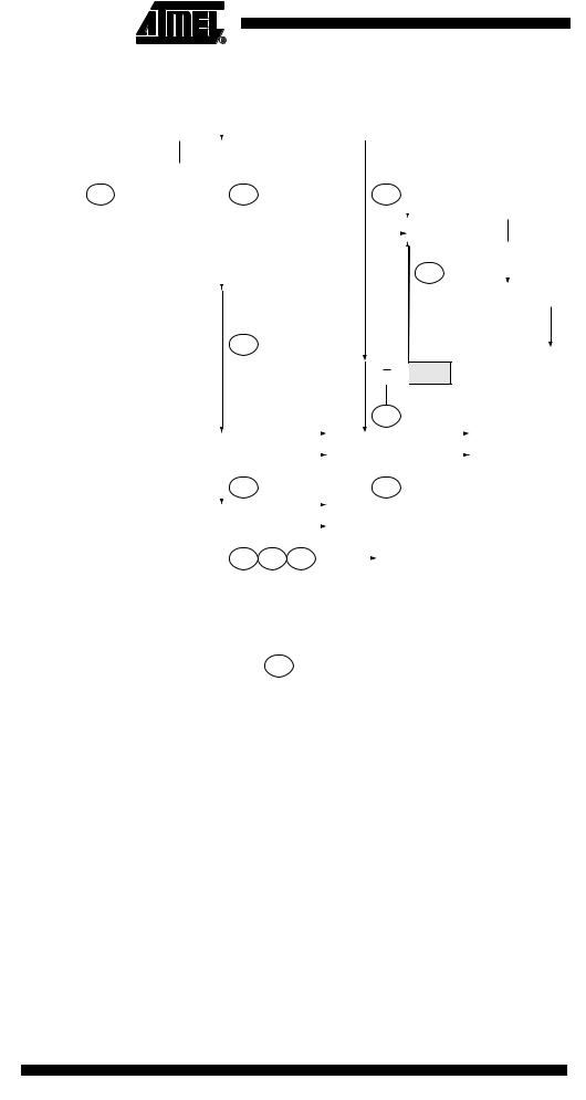
Figure 87. Formats and States in the Master Transmitter Mode
MT
Successfull |
|
|
|
|
|
|
|
|
|
|
|
|
|
|
|
|
|
|
|
|
|
|
|
|
|
|
|
|
|
|
|
|
|
|
|
|
|
|
|
|
|
|
|
|
|
|
|
|
|
|
|
|
|
S |
SLA |
W |
|
A |
DATA |
A |
P |
|
|
||||||||
transmission |
|
|
|
||||||||||||||
to a slave |
|
|
|
|
|
|
|
|
|
|
|
|
|
|
|
|
|
receiver |
|
|
|
|
|
|
|
|
|
|
|
|
|
|
|
|
|
|
|
|
|
|
|
|
|
|
|
|
|
|
|
|
|
|
|
|
$08 |
|
|
$18 |
|
|
$28 |
|
|
|
|
|
|||||
Next transfer |
|
|
|
|
|
|
|
|
|
|
|
|
|
|
|
|
|
|
|
|
|
|
|
|
|
|
|
|
|
|
|
|
|
|
|
|
|
|
|
|
|
|
|
|
|
|
|
|
RS |
SLA |
W |
||
started with a |
|
|
|
|
|
|
|
|
|
|
|
|
|
||||
|
|
|
|
|
|
|
|
|
|
|
|
|
|||||
repeated start |
|
|
|
|
|
|
|
|
|
|
|
|
|
|
|
|
|
condition |
|
|
|
|
|
|
|
|
|
|
|
|
|
|
|
|
|
|
|
|
|
|
|
|
|
|
|
|
|
|
|
|
|
|
|
|
|
|
|
|
|
|
|
|
|
|
|
|
|
$10 |
|
|
|
|
|
|
|
|
|
|
|
|
|
|
|
|
|
|
|
|
|
Not acknowledge |
|
|
|
|
|
|
|
|
|
|
|
|
|
|
|
|
R |
|
|
|
|
|
|
|
|
P |
|
|
|
|
|
|
|
||
received after the |
|
|
|
|
|
A |
|
|
|
|
|
|
|
|
|
||
|
|
|
|
|
|
|
|
|
|
|
|
|
|
||||
slave address |
|
|
|
|
|
|
|
|
|
|
|
|
|
|
|
|
|
|
|
|
|
|
|
|
|
|
|
|
|
|
|
|
|
|
|
$20
MR
Not acknowledge
received after a data A P byte
|
|
|
|
|
|
|
|
|
|
|
|
|
$30 |
|
|
|
|
|||||
|
|
|
Arbitration lost in slave |
|
|
|
|
|
|
|
|
|
|
|
|
|
|
|
|
|
||
|
|
|
|
|
|
|
Other master |
|
|
|
|
|
|
|
Other master |
|||||||
|
|
|
address or data byte |
A or A |
|
continues |
|
|
|
A or A |
continues |
|||||||||||
|
|
|
|
|
|
|
|
|
|
|
|
|
|
|
|
|
|
|
|
|
|
|
|
|
|
|
|
|
|
|
|
|
|
|
|
|
|
|
|
|
|
|
|
|
|
|
|
|
|
|
|
$38 |
|
|
|
|
$38 |
|
|
|
|
|||||||
|
|
|
Arbitration lost and |
|
|
|
|
|
|
|
|
|
|
|
|
|
|
|
|
|
||
|
|
|
|
|
|
|
|
|
|
|
|
|
|
|
|
|
|
|
|
|||
|
|
|
A |
|
Other master |
|
|
|
|
|
|
|
|
|
|
|||||||
|
|
|
addressed as slave |
|
continues |
|
|
|
|
|
|
|
|
|
|
|||||||
|
|
|
|
|
|
|
|
|
|
|
|
|
|
|
|
To corresponding |
||||||
|
|
|
|
|
|
|
|
|
|
|
|
|
|
|
|
|||||||
|
|
|
|
|
|
$68 |
$78 |
$B0 |
|
|
|
|
||||||||||
|
|
|
|
|
|
|
|
|
|
states in slave mode |
||||||||||||
|
|
|
|
|
|
|
|
|
|
|
|
|
|
|
|
|||||||
|
|
|
|
|
|
|
|
|
|
|
|
|
|
Any number of data bytes |
||||||||
|
|
|
|
From master to slave |
|
DATA |
|
|
A |
|
||||||||||||
|
|
|
|
|
|
|
|
and their associated acknowledge bits |
||||||||||||||
|
|
|
|
From slave to master |
|
|
|
|
|
n |
|
|
|
This number (contained in TWSR) corresponds |
||||||||
|
|
|
|
|
|
|
|
|
|
|
||||||||||||
|
|
|
|
|
|
|
|
|
|
|
|
|
to a defined state of the Two-wire Serial Bus. The |
|||||||||
|
|
|
|
|
|
|
|
|
|
|
|
|
||||||||||
|
|
|
|
|
|
|
|
|
|
|
|
|
|
prescaler bits are zero or masked to zero |
||||||||
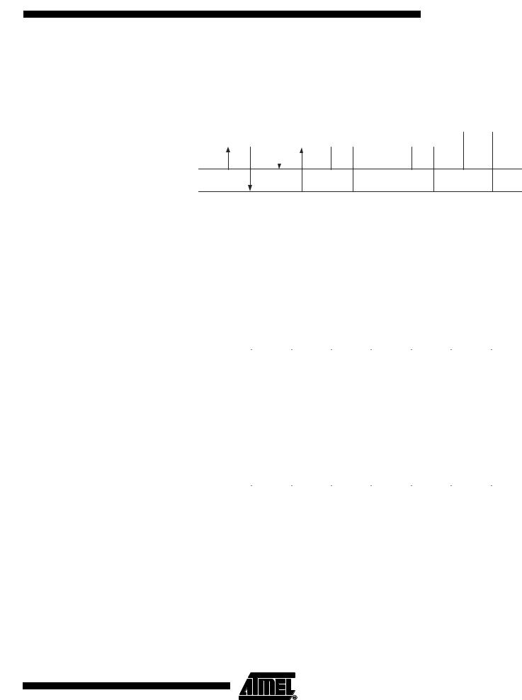
Master Receiver Mode |
In the Master Receiver mode, a number of data bytes are received from a slave trans- |
|||||||||||||||||||||
|
mitter (see Figure 88). In order to enter a Master mode, a START condition must be |
|||||||||||||||||||||
|
transmitted. The format of the following address packet determines whether Master |
|||||||||||||||||||||
Transmitter or Master Receiver mode is to be entered. If SLA+W is transmitted, MT mode is entered, if SLA+R is transmitted, MR mode is entered. All the status codes mentioned in this section assume that the prescaler bits are zero or are masked to zero.
184 ATmega32(L)
2503F–AVR–12/03
ATmega32(L)
Figure 88. Data Transfer in Master Receiver Mode
|
|
|
|
|
|
|
VCC |
|
|
|
|
|
|
|
|
|
|
|
|
|
|
|
|
|
|
|
|
|
|
|
|
|
|
|
|
|
|
|
|
|
|
|
|
|
|
|
|
Device 1 |
|
Device 2 |
|
Device 3 |
........ |
|
|
|
|
|
|
|
|
|
|
|
|
Device n |
|
|
R1 |
|
R2 |
|
|||||||
MASTER |
|
|
SLAVE |
|
|
|
|
|
|||||||
RECEIVER |
|
TRANSMITTER |
|
|
|
|
|
|
|
|
|
|
|
|
|
|
|
|
|
|
|
|
|
|
|
|
|
|
|
|
|
|
|
|
|
|
|
|
|
|
|
|
|
|
|
|
|
|
|
|
|
|
|
|
|
|
|
|
|
|
|
|
|
SDA
SCL
A START condition is sent by writing the following value to TWCR:
TWCR |
TWINT |
TWEA |
TWSTA |
TWSTO |
TWWC |
TWEN |
– |
TWIE |
Value |
1 |
X |
1 |
0 |
X |
1 |
0 |
X |
|
|
|
|
|
|
|
|
|
TWEN must be written to one to enable the Two-wire Serial Interface, TWSTA must be written to one to transmit a START condition and TWINT must be set to clear the TWINT Flag. The TWI will then test the Two-wire Serial Bus and generate a START condition as soon as the bus becomes free. After a START condition has been transmitted, the TWINT Flag is set by hardware, and the status code in TWSR will be $08 (See Table 74). In order to enter MR mode, SLA+R must be transmitted. This is done by writing SLA+R to TWDR. Thereafter the TWINT bit should be cleared (by writing it to one) to continue the transfer. This is accomplished by writing the following value to TWCR:
TWCR |
TWINT |
TWEA |
TWSTA |
TWSTO |
TWWC |
TWEN |
– |
TWIE |
Value |
1 |
X |
0 |
0 |
X |
1 |
0 |
X |
|
|
|
|
|
|
|
|
|
When SLA+R have been transmitted and an acknowledgement bit has been received, TWINT is set again and a number of status codes in TWSR are possible. Possible status codes in master mode are $38, $40, or $48. The appropriate action to be taken for each of these status codes is detailed in Table 75. Received data can be read from the TWDR Register when the TWINT Flag is set high by hardware. This scheme is repeated until the last byte has been received. After the last byte has been received, the MR should inform the ST by sending a NACK after the last received data byte. The transfer is ended by generating a STOP condition or a repeated START condition. A STOP condition is generated by writing the following value to TWCR:
TWCR |
TWINT |
TWEA |
TWSTA |
TWSTO |
TWWC |
TWEN |
– |
TWIE |
Value |
1 |
X |
0 |
1 |
X |
1 |
0 |
X |
|
|
|
|
|
|
|
|
|
A REPEATED START condition is generated by writing the following value to TWCR:
TWCR |
TWINT |
TWEA |
TWSTA |
TWSTO |
TWWC |
TWEN |
– |
TWIE |
Value |
1 |
X |
1 |
0 |
X |
1 |
0 |
X |
|
|
|
|
|
|
|
|
|
After a repeated START condition (state $10) the Two-wire Serial Interface can access the same slave again, or a new slave without transmitting a STOP condition. Repeated START enables the master to switch between slaves, Master Transmitter mode and Master Receiver mode without losing control over the bus.
185
2503F–AVR–12/03

Table 75. Status Codes for Master Receiver Mode
Status Code |
|
Application Software Response |
|
|
||||
(TWSR) |
Status of the Two-wire Serial |
|
|
To TWCR |
|
|
||
Prescaler Bits |
Bus and Two-wire Serial Inter- |
|
|
|
|
|||
To/from TWDR |
STA |
STO |
TWINT |
TWEA |
|
|||
are 0 |
face Hardware |
Next Action Taken by TWI Hardware |
||||||
|
||||||||
|
|
|
|
|
||||
$08 |
A START condition has been |
Load SLA+R |
0 |
0 |
1 |
X |
SLA+R will be transmitted |
|
|
transmitted |
|
|
|
|
|
ACK or NOT ACK will be received |
|
$10 |
A repeated START condition |
Load SLA+R or |
0 |
0 |
1 |
X |
SLA+R will be transmitted |
|
|
has been transmitted |
|
|
|
|
|
ACK or NOT ACK will be received |
|
|
|
Load SLA+W |
0 |
0 |
1 |
X |
SLA+W will be transmitted |
|
|
|
|
|
|
|
|
Logic will switch to masTer Transmitter mode |
|
$38 |
Arbitration lost in SLA+R or NOT |
No TWDR action or |
0 |
0 |
1 |
X |
Two-wire Serial Bus will be released and not addressed |
|
|
ACK bit |
|
|
|
|
|
slave mode will be entered |
|
|
|
No TWDR action |
1 |
0 |
1 |
X |
A START condition will be transmitted when the bus |
|
|
|
|
|
|
|
|
becomes free |
|
$40 |
SLA+R has been transmitted; |
No TWDR action or |
0 |
0 |
1 |
0 |
Data byte will be received and NOT ACK will be |
|
|
ACK has been received |
|
|
|
|
|
returned |
|
|
|
No TWDR action |
0 |
0 |
1 |
1 |
Data byte will be received and ACK will be returned |
|
|
|
|
|
|
|
|
|
|
$48 |
SLA+R has been transmitted; |
No TWDR action or |
1 |
0 |
1 |
X |
Repeated START will be transmitted |
|
|
NOT ACK has been received |
No TWDR action or |
0 |
1 |
1 |
X |
STOP condition will be transmitted and TWSTO Flag will |
|
|
|
|
|
|
|
|
be reset |
|
|
|
No TWDR action |
1 |
1 |
1 |
X |
STOP condition followed by a START condition will be |
|
|
|
|
|
|
|
|
transmitted and TWSTO Flag will be reset |
|
$50 |
Data byte has been received; |
Read data byte or |
0 |
0 |
1 |
0 |
Data byte will be received and NOT ACK will be |
|
|
ACK has been returned |
|
|
|
|
|
returned |
|
|
|
Read data byte |
0 |
0 |
1 |
1 |
Data byte will be received and ACK will be returned |
|
$58 |
Data byte has been received; |
Read data byte or |
1 |
0 |
1 |
X |
Repeated START will be transmitted |
|
|
NOT ACK has been returned |
Read data byte or |
0 |
1 |
1 |
X |
STOP condition will be transmitted and TWSTO Flag will |
|
|
|
|
|
|
|
|
be reset |
|
|
|
Read data byte |
1 |
1 |
1 |
X |
STOP condition followed by a START condition will be |
|
|
|
|
|
|
|
|
transmitted and TWSTO Flag will be reset |
|
186 ATmega32(L)
2503F–AVR–12/03