

- •VOLUME 3
- •CONTRIBUTOR LIST
- •PREFACE
- •LIST OF ARTICLES
- •ABBREVIATIONS AND ACRONYMS
- •CONVERSION FACTORS AND UNIT SYMBOLS
- •EDUCATION, COMPUTERS IN.
- •ELECTROANALGESIA, SYSTEMIC
- •ELECTROCARDIOGRAPHY, COMPUTERS IN
- •ELECTROCONVULSIVE THERAPHY
- •ELECTRODES.
- •ELECTROENCEPHALOGRAPHY
- •ELECTROGASTROGRAM
- •ELECTROMAGNETIC FLOWMETER.
- •ELECTROMYOGRAPHY
- •ELECTRON MICROSCOPY.
- •ELECTRONEUROGRAPHY
- •ELECTROPHORESIS
- •ELECTROPHYSIOLOGY
- •ELECTRORETINOGRAPHY
- •ELECTROSHOCK THERAPY.
- •ELECTROSTIMULATION OF SPINAL CORD.
- •ELECTROSURGICAL UNIT (ESU)
- •EMERGENCY MEDICAL CARE.
- •ENDOSCOPES
- •ENGINEERED TISSUE
- •ENVIRONMENTAL CONTROL
- •EQUIPMENT ACQUISITION
- •EQUIPMENT MAINTENANCE, BIOMEDICAL
- •ERGONOMICS.
- •ESOPHAGEAL MANOMETRY
- •EVENT-RELATED POTENTIALS.
- •EVOKED POTENTIALS
- •EXERCISE FITNESS, BIOMECHANICS OF.
- •EXERCISE, THERAPEUTIC.
- •EXERCISE STRESS TESTING
- •EYE MOVEMENT, MEASUREMENT TECHNIQUES FOR
- •FETAL MONITORING
- •FETAL SURGERY.
- •FEVER THERAPY.
- •FIBER OPTICS IN MEDICINE
- •FICK TECHNIQUE.
- •FITNESS TECHNOLOGY.
- •FIXATION OF ORTHOPEDIC PROSTHESES.
- •FLAME ATOMIC EMISSON SPECTROMETRY AND ATOMIC ABSORPTION SPECTROMETRY
- •FLAME PHOTOMETRY.
- •FLOWMETERS
- •FLOWMETERS, RESPIRATORY.
- •FLUORESCENCE MEASUREMENTS
- •FLUORESCENCE MICROSCOPY.
- •FLUORESCENCE SPECTROSCOPY.
- •FLUORIMETRY.
- •FRACTURE, ELECTRICAL TREATMENT OF.
- •FUNCTIONAL ELECTRICAL STIMULATION
- •GAMMA CAMERA.
- •GAMMA KNIFE
- •GAS AND VACUUM SYSTEMS, CENTRALLY PIPED MEDICAL
- •GAS EXCHANGE.
- •GASTROINTESTINAL HEMORRHAGE
- •GEL FILTRATION CHROMATOGRAPHY.
- •GLUCOSE SENSORS
- •HBO THERAPY.
- •HEARING IMPAIRMENT.
- •HEART RATE, FETAL, MONITORING OF.
- •HEART VALVE PROSTHESES
- •HEART VALVE PROSTHESES, IN VITRO FLOW DYNAMICS OF
- •HEART VALVES, PROSTHETIC
- •HEART VIBRATION.
- •HEART, ARTIFICIAL
- •HEART–LUNG MACHINES
- •HEAT AND COLD, THERAPEUTIC
- •HEAVY ION RADIOTHERAPY.
- •HEMODYNAMICS
- •HEMODYNAMIC MONITORING.
- •HIGH FREQUENCY VENTILATION
- •HIP JOINTS, ARTIFICIAL
- •HIP REPLACEMENT, TOTAL.
- •HOLTER MONITORING.
- •HOME HEALTH CARE DEVICES
- •HOSPITAL SAFETY PROGRAM.
- •HUMAN FACTORS IN MEDICAL DEVICES
- •HUMAN SPINE, BIOMECHANICS OF
120.Rogers SH. Work physiology—fatigue and recovery. The human factors fundamentals. In: Salvendy G, editor. Handbook of Human Factors and Ergonomics. 2nd ed. New York: Wiley; 1997. p 268–297.
121.Roy F, Robillard P. Effectiveness of and compliance to preventive measures against the occupational transmission of human immunodeficiency virus. Scand J Work Environ Health 1994;20(6):393–400.
See also CODES AND REGULATIONS: MEDICAL DEVICES; EQUIPMENT MAINTENANCE, BIOMEDICAL; HOME HEALTH CARE DEVICES; MONITORING IN ANESTHESIA; SAFETY PROGRAM, HOSPITAL.
HUMAN SPINE, BIOMECHANICS OF
VIJAY K. GOEL
ASHOK BIYANI
University of Toledo, and
Medical College of Ohio,
Toledo Ohio
LISA FERRARA
Cleveland Clinic Foundation
Cleveland, Ohio
SETTI S. RENGACHARY
Detroit, Michigan
DENNIS MCGOWAN
Kearney Notabene
INTRODUCTION
From a bioengineer’s perspective, bio the spine involves an understanding of the interaction among spinal components to provide the desired function in a normal person. Thereafter, one needs to analyze the role of these elements in producing instability. Abnormal motion may be due to external environmental factors to which the spine is subjected to during activities of daily living (e.g., impact, repetitive loading, lifting) degeneration, infectious diseases, injury or trauma, disorders, and/or surgery. Furthermore, the field of spinal biomechanics encompasses a relationship between conservative treatments, surgical procedures, and spinal stabilization techniques. Obviously, the field of spinal biomechanics is very broad and it will not be practical to cover all aspects in one article. Consequently, this article describes several of these aspects, especially in the cervical and thoraco-lumbar regions of the human spine. A brief description of the spine anatomy follows since it is a prerequisite for the study of bio the human spine.
SPINE ANATOMY
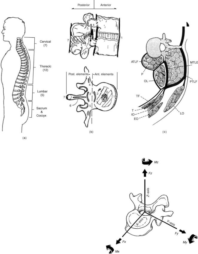
The human spinal column consists of 33 vertebras interconnected by fibrocartilaginous intervertebral disks (except the upper most cervical region), articular facet capsules, ligaments, and muscles. Normally, there are 7 cervical vertebras, 12 thoracic vertebras, 5 lumbar vertebras, and 5 fused sacral vertebras, Fig. 1a (1). When viewed
HUMAN SPINE, BIOMECHANICS OF |
547 |
in the frontal plane, the spine generally appears straight and symmetric while revealing four curves in the sagittal plane. The curves are anteriorly convex or lordotic in the cervical and lumbar regions, and posteriorly convex or kyphotic in the thoracic and sacrococcygeal regions. The center of gravity of the spinal column generally passes from the dens of the axis (C2) through the vertebra to the promontory of the sacrum (2,3). The ligamentous spine anatomy can be best described through a functional spinal unit (FSU, Fig. 1b), comprising the two adjacent vertebras, the disk in between, and the other soft tissues structures. This segment can be divided into anterior and posterior columns. The anterior column consists of the posterior longitudinal ligament, intervertebral disk, vertebral body, and anterior longitudinal ligament. Additional stability is provided by the muscles that surround the ligamentous spine, Fig. 1c. The motion of this segment can be described as rotation about three axes and translation along the same axes, Fig. 2. In the following paragraphs, the anatomy of the cervical region is described in some detail followed by a descriptive section discussing the anatomy of the lumbar spine.
Cervical Spine Anatomy
The cervical spine usually is subdivided in two regions (upper and lower), based on the functional aspects and anatomical differences between the two regions. The lumbar region anatomy, in principle, is similar to the lower cervical region.
Upper Cervical Spine (C0-C1-C2)
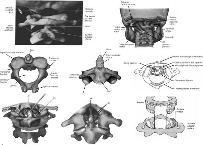
The upper cervical spine has been commented to be the most complex combination of articulations in the human skeleton. This region is also commonly called the ‘‘cervicovertebral junction’’ or the ‘‘craniovertebral junction’’ (CVJ). It is composed of three bony structures: the occipital bone (C0), the atlas (C1), and the axis (C2, Fig. 3). The atlas (C1), serves to support the skull. The atlas is atypical of other cervical vertebras in that it possesses neither a vertebral body nor a spinous process. The lateral masses of the atlas have both superior and inferior articular facets. The superior facets are elongated, kidney-shaped, and concave, and serve to receive the occipital condyles. The inferior facets are flatter and more circular and permit axial rotation. Transverse processes extend laterally from each lateral mass. Within each transverse process is a foramen that is bisected by the vertebral artery. The second cervical vertebra, or axis (C2), is also atypical of other cervical vertebra due to its osseous geometry (5,6). The most noteworthy geometric anomaly is the odontoid process, or dens. The odontoid process articulates with the anterior arch of the atlas. Posterior and lateral to the odontoid process are the large, convex superior facets that articulate with the inferior facets of C1. The inferior facets of C2 articulate with the superior facets of C3. The axis contains a large bifid spinous process that is the attachment site delineating the craniovertebral and subaxial musculature and ligament anatomies.
548 HUMAN SPINE, BIOMECHANICS OF
Figure 1. The ligamentous human spine. (a) The side view showing the three curvatures. (b) The functional spinal unit (FSU) depicts the spinal elements that contribute to its stability. (c) Additional stability is provided by the muscles that surround the spine. (Taken from Ref. 1.)
The trabecular anatomy of weight bearing bones provides information about the normal loading patterns of the bones, fracture mechanisms, and fixation capabilities. According to Heggeness and Doherty (6) the medial, anterior cortex of the odontoid process (1.77 mm at the anterior promontory) was found to be much thicker than the anterolateral (1.00 mm), lateral (1.08 mm), and posterior (0.84 mm) aspects of the axis. These authors feel that this is suggestive of bending and torsional load carrying capabilities. The same was found for the vertebral body, with thinner cortices were noted in the anterolateral and posterior directions. The trabecular bone in the tip of the odontoid process was found to be dense, maximizing in the anterior aspect of the medullary canal. One observation made by the authors was an area of cortical bone density at the center near the tip, which would seem to indicate that this area experiences elevated external forces, perhaps due to local ligamentous attachments. The lateral masses immediately inferior to the facets demonstrated dense regions of trabecular bone, with individual trabeculas spanning from this region to the inferior end plate, suggestive of a major axial load path.
The ligamentous structures of the upper cervical spine form a complex architecture (Fig. 3) that serves to join the
Figure 2. The spinal motion consists of six components (three translations and three rotations). (Adapted from Ref. 2.)
HUMAN SPINE, BIOMECHANICS OF |
549 |
Figure 3. The anatomy of the upper region of the cervical spine C0 (occiput)-C1 (Atanlanto)-C2 (Axial). (Taken from Ref. 4c.)
vertebras, allow limited motion within and between levels, and provide stability. The cruciform ligament as a whole consists of two ligaments: the atlantal transverse ligament and the inferior–superior fascicles. The transverse ligament attaches between the medial tubercles of the lateral masses of the atlas, passing posterior to the odontoid process. Attachment of the cervical spine to the skull is also achieved by the paired alar ligaments. These ligaments run bilaterally from the occiptal condyles inferiolaterally to the tip of the odontoid process. The alar ligaments also contain fibers that run bilaterally from the odontoid process anterolaterally to the atlas. These ligaments have been identified as a check against overaxial rotation of the craniovertebral junction. Extending from the body of the axis to the inner surface of the occiput, the tectorial membrane is the most posterior ligament and actually represents the cephalad extension of the subaxial posterior longitudinal ligament. The tectorial membrane has been implicated as a check against extreme flexion motion. The apical dental ligament extends from the anterior portion of the magnum foramen to the tip of the odontoid process. The accessory atlantoaxial ligaments are bilateral structures that run between the base of the odontoid process and the lateral masses of the atlas. The most anterior of the major ligaments is the anterior longitudinal ligament.
This ligament extends inferiorly from the anterior margin of the foramen magnum to the superior surface of the anterior arch of the atlas at the anterior tuberosity. The ligament continues inferiorly to the anterior aspect of the axial body. The nuchal ligament (ligamentum nuchae) extends from the occiput to the posterior tubercle of the axis, continuing inferiorly to the spinous process of the subaxial vertebras (7).
There are six synovial articulations in the occipitoatlantoaxial complex: the paired atlanto-occiptal joints, the paired atlantoaxial joints, the joint between the odontoid process and the anterior arch of the atlas, and the joint formed by the transverse ligament and the posterior aspect of the odontoid process, Fig. 3. The bilateral atlantooccipital joints are formed from the articulation of the occiptal condyles with the superior facets of the atlas. These joints are relatively stable due to the high degree of congruence between the opposing surfaces and the marked rounding that is displayed by both sides. They allow flexion and extension, limited lateral bending, and almost no rotation. The lack of allowed rotation is thought to be due to the ellipsoid form of the joint itself. Bilateral articulation of the inferior facets of the atlas with the superior facets of the axis form the atlantoaxial joints. Relatively small contact areas and opposed convexity
550 HUMAN SPINE, BIOMECHANICS OF
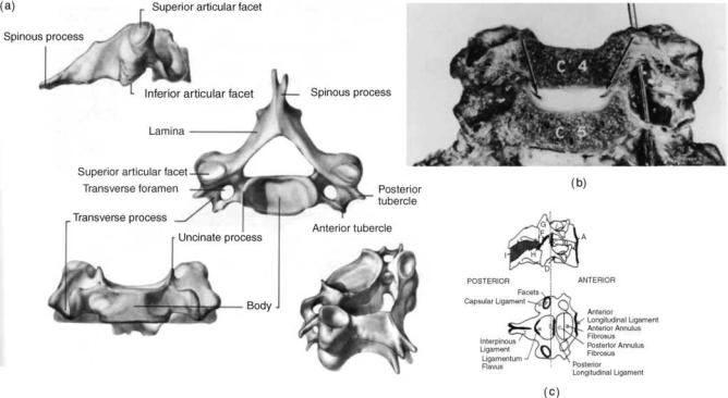
Figure 4. Anatomy of the lower cervical spine region. (Taken from Ref. 4d.)
result in a rather unstable joint. Movement is permitted in almost all six degrees of freedom: left and right axial rotation, flexion–extension, right and left lateral bending. Anteroposterior translation stability of this articulation is highly dependent on the transverse ligament. The odontoid process articulates anteriorly with the posterior aspect of the anterior atlantal ring. The joint is actually a bursal joint, with absence of specific capsular ligaments. The posterior aspect of the odontoid process and the transverse ligament form a joint via a bursa junction, creating the most unique articulation in the craniovertebral junction. This is necessitated by the large degree of axial rotation afforded at the atlantoaxial level.
Lower Cervical Spine (C3-C7). The lower cervical spinal vertebral column consists of osseous vertebras separated by fibrocartilaginous intervertebral disks anteriorly, facet joint structures posteriorly, and a multitude of ligamentous structures that provide stability and serve as motion control. Motion between adjacent vertebras is relatively limited due to these constraints, although overall motion of the lower cervical region is quite extensive. The lower cervical spine consists of five vertebras (C3-C7).
Cervical Vertebrae (Fig. 4a): The vertebral body is roughly in the shape of an elliptical cylinder and has a concave superior surface (due to the uncinate processes) and a convex inferior surface. A thin cortical shell ( 0.3 mm thick anteriorly and 0.2 mm thick posteriorly) surrounds the cancellous bone of the inner vertebral body, while the superior and inferior surfaces of the vertebral body form the cartilaginous endplates, to which the intervertebral disks are attached. The superior aspect of each
vertebra contains the uncinate process or uncus, a dorsolateral bilateral bony projection, which gives the body a concave shape superiorly in the coronal plane and allows for the vertebral body to fit around the convex inferior surface of the immediately superior vertebra. The height of these processes vary from level to level, but the highest uncinate processes are located at C5 and C6 (as high as 9 mm from the flat surface of the endplate) and the smallest are located at C3 and C7 (8–10). Vertebral bodies transmit the majority of load.
The transverse process of the vertebra contains the intervertebral foramen. The intervertebral foramen is elliptical or round in shape, and hides and protects the neurological and vascular structures of the cervical spine, specifically the vertebral artery. Also, the rostral side of each bilateral transverse process is grooved to allow space for the exiting spinal nerve root.
The bilateral diarthroidal facet (or zygapophyseal) joints are located posteriorly to the pedicles both superiorly and inferiorly. The average orientation for the C3-C7 facet joints is 458 from the transverse plane, with steeper inclinations in the lower segments (11). This inclination allows far less axial rotation than occurs in the upper cervical spine. Together with the vertebral body (and intervertebral disks), the facets fulfill the primary role of load bearing in the spine. Typically a ‘‘three-column’’ aspect is applied to the cervical spine, consisting of bilateral facets and the anterior column (vertebral body plus intervertebral disk).
The pedicles, lamina, and spinous process of the cervical spine are made of relatively dense bone and, together with the posterior aspect of the vertebral body, form the spinal
HUMAN SPINE, BIOMECHANICS OF |
551 |
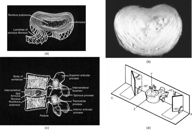
Figure 5. The anatomy of the lumbar spine. (a) and (b) show schematics of the disk and an actual disk (c) A FSU in the lumbar region. (d) The facet orientation in the lumbar region is more sagittal as compared to the other regions of the spine. (Adapted from Ref. 2.)
canal, within which lies the spinal cord. There are many ligament attachment points in this region and ligaments allow for resistance of flexion motion in the cervical spine.
The typical sagittal cervical spine alignment is thought to be a lordotic contour (11–15). The total average cervical lordosis was found to be 40 9.78 for C0-C7, with the majority of this lordosis occurring at the C1-C2 level (31.9 7.08), and only 15% of the total lordosis occurring at the C4-C7 levels combined. The normal population seem to exhibit lordosis that ranges between 15 and 408.
The Intervertebral Disk
Figure 5 forms the main articulation between adjacent vertebral bodies in the spine. It has the ability to transmit and distribute loads that pass between adjacent vertebral bodies. Its structure is a composite formation of outer layers of lamellas sheets called the annulus fibrosis, which surrounds the inner region of hydrophylic proteoglycan gel embedded in a collagen matrix called the nucleus pulposus. The material properties of the intervertebral disk appear to change markedly as a result of the aging process The matrix in which collagen and elastin fibers are embedded is composed of proteoglycan aggregates formed from
proteoglycan subunits, hyaluronic acid, and link protein (16). In soft tissues, such as the intervertebral disk and cartilage, the proteoglycan aggregates are immobilized within a fibrous network and play a major biological role in the structure of collagen, in turn playing a major mechanical role in the intervertebral disk integrity. The viscoelastic properties of the intervertebral disk can be attributed to the interaction between the collagen fibrils and proteoglycan matrix composing the nucleus pulposus of the intervertebral disk. The proteoglycans function to attract fluids into the matrix, while the collagen fibers provide the tensile strength to the disk. As the human spine ages, the osmotic properties of the intervertebral disk decline, and the disks become dehydrated with age, causing a reduction in overall disk height.
The annulus fibrosis of the disk consists of a series of approximately twelve 1-mm thick lamellas sheets, each composed of collagen fibers. The anterior lamellas are generally thicker and more distinct than the posterior lamellas. According to a study by Pooni et al.(9), the collagen fibers running through a single laminar sheet are oriented at 658 ( 2.58) with respect to the vertical axis. These fibers alternate direction in concentric lamellas to form a cross-pattern. The annulus fibrosus develops lesions as it ages.
552 HUMAN SPINE, BIOMECHANICS OF
The nucleus pulposus of the intervertebral disk consists of a hydrophylic proteoglycan gel embedded in a collagen matrix. The nucleus pulposus contains 80–88% water content in a young adult spine and occupies 30–50% of the total intervertebral disk volume (16,17). However, with aging the nucleus undergoes rapid fibrosis and loses its fluid properties such that, by the third decade of life, there is hardly any nuclear material distinguishable (18). In a normal healthy intervertebral disk, the nucleus pulposus is glossy in appearance.
Luschka’s joints are something special in the cervical region. The human cervical intervertebral disk contains fissures, called Luschka’s joints or uncovertebral joints that run along the uncinate process and radiate inward toward the nucleus (Fig. 4a and b). These fissures run through the annular lamellas and the adjacent annular fibers are oriented such that they run parallel to the fissure (19–21). These fissures appear within the latter part of the first decade of life and continue to grow in size as aging occurs (8). Although some argument exists as to the definition of the fissures as true joints or pseudojoints, the fissures have been shown to exist as a natural part of the aging process (19,20) and therefore are important aspects of biomechanical modeling of the human cervical intervertebral disks.
The ligaments of the cervical spine (Fig. 4c) provide stability and act to limit excessive motions of the vertebras, thereby preventing injury during physiologic movement of the spine. Ligaments can only transmit tensile forces, impeding excessive motion, but do follow the principles of Wolff’s law, where the tissue will remodel and realign along lines of tensile stress. The ligaments that are biomechanically relevant include the anterior longitudinal ligament (ALL), posterior longitudinal ligament (PLL), ligamentum flavum (LF), interspinous ligament (ISL), and the capsular ligaments (CAP). The ALL and PLL each traverse the length of the spine. The ALL originates at an insertion point on the inferior occipital surface and ends at the first segment of the sacrum. It runs along the anterior vertebral bodies, attached to the osseous bodies and loosely attached to the intervertebral disks as well. The ALL is under tension when the cervical spine undergoes extension. The PLL also runs the length of the spine down the posterior aspect of the vertebral bodies, originating at the occiput and terminating at the coccyx. Similar to the ALL, it is firmly attached to the osseous vertebral bodies and to the intervertebral disks. The PLL is under tension when the spine undergoes flexion. The ligamentum flavum couples the laminas of adjacent vertebras. It is an extremely elastic ligament due to the higher percentage of elastin fibers (65–70%) as compared to other ligaments in the spine and any other structure in the human body. The LF resists flexion motion and lengthens during flexion and shortens during extension. The high elastin content minimizes the likelihood of buckling during extension. It is under slight tension when the spine is at rest and acts as a tension band in flexion. Torsion also places the ligamentum flavum under tension, and restraint of rotation may also be a significant function. The ISL insertion points lie between adjacent spinous processes. The ligament is typically slack when the head is in a neutral posture and only becomes
tensile when enough flexion motion has occurred such that other ligaments have undergone significant tension, such as the capsular ligaments, PLL and LF. Additionally, the ISL insertion points are such that it is ideal for resisting the larger flexion rotations that can occur as a result of excessive flexion loading. The capsular ligaments (CAPs) enclose the cervical facet joints and serve to stabilize the articulations of these joints and limit excessive motions at these joints. Generally, the fibers are oriented such that they lie perpendicular to the plane of the facet joints. These ligaments potentially also serve to keep the facets aligned and allow for the coupled rotations.
Lumbar Spine Anatomy
The basic structural components of the lumbar spine are the same as that of the lower cervical spine with differences in size, shape, and orientation of the structures due to functional requirements being different from that of the cervical region, Fig. 5. For example, the lumbar vertebras are bigger in size, because of the higher axial loads they carry. With regard to the peripheral margin of the interverebral disk, annulus fibrosus is composed of 15–20 layers of collagenous fibrils obliquely running from one cartilage end plate to the other and crossing at 1208 angles. As one progresses from the cervical into the thoracic region, the facet joints gradually orient themselves parallel with the frontal plane. The transition from the thoracic region into the lumbar region is indicated by a progressive change from the joints in the frontal plane to a more sagittal plane (4,22). This transition in facet orientation from the thoracic to the lumbar spine creates a different series of degenerative complications and disorders in the spine. Sagittal alignment of the facet joints increases the risk of subaxial and spondylolisthesis of the lumbar spine.
CLINICAL BIOMECHANICS OF THE NORMAL SPINE
The three basic functions of the spine are to protect the vital spinal cord, to transmit loads, and to provide the flexibility to accomplish activities of daily living. Components that provide stability to the spine are divided into four groups as follows:
1. Passive stabilizers: Passive stabilization is provided by the shape and size of vertebras and by the size, shape, and orientation of the facet joints that link them.
2.Dynamic stabilizers: Dynamic stabilization is provided by viscoelastic structures, such as the ligaments, capsules, and annulus fibrosus. The cartilage of the facet joints also acts as a damper.
3.Active stabilizers: Active voluntary or reflex stabilization is provided by the muscular system that governs the spine, Fig. 1c.
4.Hydrodynamic stabilizer: Hydrodynamic stabilization is due to the viscous nucleus pulposus.
The combination of these elements generates the characteristics of the entire spine. The diskussion of the kinematics will begin by further analyzing spinal elements as

either passive or active. It will then progress into the effect these stabilizers have on the different portions of the spine.
Passive Elements
The vertebral body acts to passively resist compressive force. The size, mineral content, and orientation of the cancellous bone of each vertebral body increase–change as one descends in the caudal direction, which is a morphologic response to the increasing weight it must bear (4). The cortical shell on the vertebral body serves as the chief load path. The shell also provides a rigid link in the FSU, and a platform for attachment of the intervertebral disk, muscles, and the anterior and posterior longitudinal ligaments. The transition area of the motion segment is the endplate. This serves to anchor the intervertebral disk to the vertebral body. Note that the endplate starts out as growth cartilage and transitions into bone as aging occurs (22). The disk acts as both a shock absorber and an intervertebral joint because the relative flexibility of the intervertebral disk is high when compared to the vertebral body. The intervertebral disk resists compression, tension, shear, bending, and torsion
(4). It is relatively resistant to failure in axial compression while its annular portions fail in axial torsion first (23).
Dynamic Stabilizers
Although bone is viscoelastic in nature, it serves more as a structural component within the spine that passively resists axial forces and can transmit forces along the spinal column. The soft tissue spinal structures (ligamentous, capsules, annulus fibrosis) are far more elastic as compared to bone behavior and stabilize the spine in a dynamic manner, where rapid vamping of oscillatory motions occur. The main function of the facet joints is to pattern the motions of the spine so that during activities of daily living the neural elements are not strained beyond the physiological limits. Therefore, they play a major role in determining the range of motion across a joint and as a damper to any possible dynamic loading. The amount of stability provided by the facet joints depends on extent of the capsular ligaments, their shape, orientation, and level within the spine (2). For example, the thoracic facets have a limited capsular reinforcement and facilitate axial rotation, which is in contrast to the lumbar region where the facet ligaments are more substantial and the joint plane is configured to impede axial motion (24).
From a biomechanical perspective, the ligaments respond to tensile forces only (1). The effectiveness of a ligament depends on the morphology and the moment arm through which it acts. That is, not only the strength, but also the longer lever arm a ligament has, the more it participates in the stabilization of the spine (4). Ligaments also obey Wolff’s law. The ligaments also undergo remodeling along the lines of applied tensile stresses in response to chronic loads, just like bones. The ligamentum flavum acts as a protective barrier for the entire spine.
Active Stabilizers
Muscles contribute significantly to maintain the stability of the spinal column under physiological conditions. Decreasing the muscle forces acting on a FSU, increases the motion
HUMAN SPINE, BIOMECHANICS OF |
553 |
and loading of the ligaments. A thoracolumbar (T1-sacrum) spinal column that is devoid of musculature is an unstable structure, with a load-carrying capacity of <25 N (24). However, with properly coordinated muscle action, the spine can sustain large loads, which is exemplified by the action of weight lifters (24).
The internal force resisted by the muscle depends on factors such as cross-section and length at the initiation of contraction. The maximum force develops at approximately 125% of muscle resting length. In contrast, at approximately one-half of its resting length, the muscle develops very low force. The muscle stress (the maximum force per unit area) ranges from 30 to 90 N cm 2 (25,26). Macintosh et al. (27) performed a modeling study based on radiographs from normal subjects to determine the effects of flexion on the forces exerted by the lumbar muscles. They found that the compressive forces and moments exerted by the back muscles in full flexion are not significantly different from those in the upright posture.
The remainder of this section is devoted to the biomechanics of the individual sections of the spinal column in a normal healthy person. Various methods for recording data with varying degrees of accuracy and repeatability are used ranging from the use of different types of goniometers, radiographs, in vitro cadaver based studies, magnetic resonance imaging (MRI) to visual estimation of motion. Although the value of assessing the ROM is not yet documented, the understanding and knowledge of normal ageand sex-related values of ROM is the basis for analysis of altered and possibly pathologic motion patterns as well as decreased or increased ROM (23,28). The issue of spinal instability (stability), although controversial in its definition, has immense clinical significance in the diagnosis and treatment of spinal disorders. Maintaining a normal range of motion in the spine is linked to spinal stability. The spine needs to maintain its normal range of motion to remain stable and distribute forces while bearing loads in several directions. The typical motion, for example, in response to the flexion–extension loads, as determined using cadaver testing protocols, is shown in Fig. 6. The two motion
|
|
|
|
|
(L4-S1) |
|
|
|
Rotation/Translation |
(deg/mm) |
15 |
|
Extension |
Flexion |
|
RX |
|
–5 |
|
|
|
|
|
|
||
|
|
10 |
|
|
|
|
|
TZ H |
|
|
ROM |
|
|
|
|
|
|
|
|
5 |
|
|
|
|
|
|
|
|
0 |
|
|
NZ |
|
|
RY,RZ, |
|
|
|
|
|
|
|
||
|
|
|
|
|
|
|
|
TX H,TY H |
|
–10 |
–2 |
–1 |
0 |
1 |
2 |
3 |
|
|
|
–3 |
||||||
Moment (N M)
Figure 6. The load-displacement response of a FSU in flexion and extension. Two of the motion components are major and the other four are minor (or coupled). The range-of-motion and neutral zones, two of the terms used to describe the motion behavior of a segment, are also shown. (Adapted from Ref. 1.)

554 HUMAN SPINE, BIOMECHANICS OF
components (Flexion/extension rotation–Rx, and A-P translation-TzH) are an order of magnitude higher than the other four. The two larger components are called the major–main motions and other four are the secondary– coupled motions. Range of motion, highlighted in the figure, will depend on the maximum load exerted on the specimen during testing. Likewise, the in vivo ranges of motion data will vary depending on the level of external force applied, that is, active or passive (2).
Biomechanics of the Occipital–Atlantoaxial Complex
(C0-C1-C2)
As a unit, the craniovertebral junction accounts for 60% of the axial rotation and 40% of the flexion–extension behavior of the cervical spine (29,30).
Flexion–Extension. Large sagittal plane rotations have been attributed to the craniovertebral junction (Tables 1 and 2). Panjabi et al. (31) reported combined flexion– extension of C0-C1 and C1-C2 of 24.5 and 22.48, respectively, confirming flexion–extension equivalence at the two levels. They also found that the occipitoatlantal joint level demonstrated a sixfold increase in extension as compared to flexion (21.0 vs. 3.58), whereas the atlantoaxial level equally distributed its sagittal plane rotation between the two rotations, 11.5 (flexion) versus 10.98 (extension). Goel et al. (32) documented coupling rotations that occur with flexion and extension. They reported one-side lateral bending values of 1.2 and 1.48 for flexion and extension, respectively, at the C0-C1 level. In addition, they found C1-C2 coupled lateral bending, associated with flexion and extension movents, were lower than seen at the C0-C1 level. The largest axial rotation reported was 1.98, which was an outcome of a C0-C1 extension of 16.58. Note that the values reported by this study do not represent range of motion data, but rather intermediate rotation due to submaximal loading. Displacement coupling occurs between the translation of the head and flexion–extension of the occi- pitoatlanto–axial complex. Translation of the occiput with respect to the axis produces flexion–extension movements in the atlas. Anterior translation of the head extends the occipitoatlantal joints, with posterior motion resulting in converse flexion of the joint. This is postulated to occur due
Table 1. Ranges of Motion Reported from In Vivo and In Vitro Studies for the Occipito-Atlantal Joint (C0-C1)a
Type of |
Total Flexion/ |
Unilateral |
Unilateral Axial |
Studyb |
Extension |
Bending |
Rotation |
|
|
|
|
In vivo |
50 |
34–40 |
0 |
In vivo |
50 |
14–40 |
0 |
In vivo |
13 |
8 |
0 |
In vivo |
30 |
10 |
0 |
In vivo |
|
|
5.2 |
In vivo |
|
|
1.0 |
In vitro |
|
|
4.0 |
In vitro |
3.5/21.0 |
5.5 |
7.2 |
aIn degrees.
bThe in vivo studies represent passive range-of-motion, whereas the in vitro studies represent motion at 1.5 N m occipital moment loading. (From Ref. 4c.)
Table 2. Ranges of Motion Reported from In Vivo and In Vitro Studies for the AtlantoAxial Joint (C1-C2)a
Type of |
Total Flexion/ |
Unilateral |
Unilateral Axial |
Studyb |
Extension |
Bending |
Rotation |
|
|
|
|
In vivo |
0 |
0 |
60 |
In vivo |
11 |
|
30–80 |
In vivo |
10 |
0 |
47 |
In vivo |
30 |
10 |
70 |
In vivo |
|
|
32.2 |
In vitro |
|
|
43.1 |
In vivo |
|
|
40.5 |
In vitro |
11.5/10.9 |
6.7 |
38.9 |
aIn degrees.
bThe in vivo studies represent passive range-of-motion, whereas the in vitro studies represent motion at 1.5 N m occipital moment loading. (From Ref. 4c.)
to the highly contoured articular surfaces of the atlantoocciptal joint.
Lateral Bending. As is shown in Tables 1 and 2, early studies have shown that occipitoatlantal lateral bending dominates the overall contribution of this motion in the occipitoatlanto–axial complex. However, this is not the finding of the most recent study. Almost all other studies indicate a significantly greater contribution from the C0C1 joint. Lateral flexion also plays an important role in rotation of the head. Rotation of the lower cervical spine (C2-T1) results in lateral flexion of this region.
Axial Rotation. Almost all of the occipitoatlanto–axial contribution to axial rotation occurs in the atlantoaxial region. Atlantoaxial rotation occurs about an axis that passes vertically through the center of the odontoid process. This axis remains halfway between the lateral masses of the atlas in both neutral and maximal rotation. In maximal rotation, there is minimal joint surface contact, and sudden overrotation of the head can lead to interlocking of the C1-C2 facets, making it impossible to rotate the head back to neutral. Table 2 lists the amount of rotation found in the atlantoaxial joint by various researchers. Although these studies have produced widely varying results, there seems to be a consensus among the more recent studies that one side axial rotation at the atlantoaxial level falls somewhere in the range of 35–458. The findings in Table 1 demonstrate that there is a relatively small contribution from the C0-C1 joint, with researchers finding between 0 and 7.28 of rotation. One interesting anatomical note concerning axial rotation is the behavior of the vertebral artery during rotation. The vertebral artery possess a loop between the atlas and axis, thus affording it over-length. Upon atlantoaxial rotation, the slack is taken up in the loop and it straightens, thus preventing overstretching and possible rupture during maximal rotation.
The instantaneous axes of rotation (IARs) for the C0-C1 articulation pass through the center of the mastoid processes for flexion–extension and through a point 2–3 cm above the apex of the dens for lateral bending. There is a slight axial rotation at C0-C1. The IARs for the C1-C2 articulation are somewhere in the region of the middle third of the dens for flexion–extension and in the center of the dens for axial rotation. Lateral bending of C1-C2 is
|
|
|
HUMAN SPINE, BIOMECHANICS OF |
555 |
|
Table 3. C3-C4 Ranges of Motion Compiled from Various In Vivo and In Vitro Studiesa,b |
|
|
|||
Type of Study |
Type of Loading |
Total Flexion/Extensionc |
Unilateral Lateral Bendingc |
Unilateral Axial Rotationc |
|
|
|
|
|
|
|
In vivo |
Max. Rotation (active) |
15.2 (3.8) |
NA |
NA |
|
In vivo |
Max. Rotation (active) |
17.6 (1.5) |
NA |
NA |
|
In vivo |
Review |
13.0 (range 7–38) |
11.0 (range 9–16) |
11.0 (range 10–28) |
|
In vivo |
Max. Rotation (active) |
13.5 (3.4) |
NA |
NA |
|
In vivo |
Max. Rotation (active) |
15.0 (3.0) |
NA |
NA |
|
In vivo |
Max. Rotation (active) |
NA |
NA |
6.5 (range 3–10) |
|
In vivo |
Max. Rotation (active) |
18.0 (range 13–26) |
NA |
NA |
|
In vitro |
1 N m |
8.5 (2.6) |
NA |
NA |
|
In vitro |
3 N m |
NA |
8.5 (1.8) |
10.7 (1.3) |
|
aIn degrees.
bSee Refs. 4b and d. cNot available ¼ NA.
controversial at the most 5–108 (4). During lateral bending, the alar ligament is responsible for the forced rotation of the second vertebra.
Middle and Lower Cervical Spine (C2-C7)
In the middle and lower cervical regions, stability and mobility must be provided; while, the vital spinal cord and the vertebral arteries must be protected. There is a good deal of flexion–extension and lateral bending in this area, Tables 3–6.
Flexion–Extension. Most of the flexion–extension motion in the lower cervical spine occurs in the central region, with the largest range of motion (ROM) generally occurring at the C5-C6 level. Except for extension, the orientation of the
cervical facets (on average, 458 in the sagittal plane) does not excessively limit spinal movements in any direction or rotation. Flexion–extension rotations are distributed throughout the entire lower cervical spine for total rotations typically in the range of 60–758 and sagittal A/P translation is usually in the range of 2–3 mm at all cervical levels (1). There is relatively little coupling effect that occurs during flexion–extension due to the orientation of the facets. There have been many published in vivo and in vitro studies reporting ‘‘normal’’ rotations at the various cervical spinal levels. These studies are in general agreement, although there appears to be a wide variation within ROM at all levels of the cervical region.
An in vitro study by Moroney et al.(33) averaged rotations among 35 adult cervical motion segments and found that average rotations ( SD) in flexion and extension
Table 4. C4-C5 Ranges of Motion Compiled from Various In Vivo and In Vitro Studiesa,b
Type of Study |
Type of Loading |
Total Flexion/Extensionc |
Unilateral Lateral Bendingc |
Unilateral Axial Rotationc |
In vivo |
Max. Rotation (active) |
17.1 (4.5) |
NA |
NA |
In vivo |
Max. Rotation (active) |
20.1 (1.6) |
NA |
NA |
In vivo |
Review |
12 (range 8–39) |
11.0 (range 0–16) |
12.0 (range 10–26) |
In vivo |
Max. Rotation (active) |
17.9 (3.1) |
NA |
NA |
In vivo |
Max. Rotation (active) |
19 (3.0) |
NA |
NA |
In vivo |
Max. Rotation (active) |
NA |
NA |
6.8 (range 1–12) |
In vivo |
Max. Rotation (active) |
20 (range 16–29) |
NA |
NA |
In vitro |
1 N m |
9.7 (2.35) |
NA |
NA |
In vitro |
3 N m |
NA |
6.3 (0.6) |
10.8 (0.7) |
aIn degrees. |
|
|
|
|
bSee Refs. 4b and d. |
|
|
|
|
cNot available ¼ NA. |
|
|
|
|
Table 5. C5-C6 Ranges of Motion Compiled from Various In Vivo and In Vitro Studiesa,b |
|
|||
Type of Study |
Type of Loading |
Total Flexion/Extensionc |
Unilateral Lateral Bendingc |
Unilateral Axial Rotationc |
|
|
|
|
|
In vivo |
Max. Rotation (active) |
17.1 (3.9) |
NA |
NA |
In vivo |
Max. Rotation (active) |
21.8 (1.6) |
NA |
NA |
In vivo |
Review |
17.0 (range 4–34) |
8.0 (range 8–16) |
10.0 (range 10–34) |
In vivo |
Max. Rotation (active) |
15.6 (4.9) |
NA |
NA |
In vivo |
Max. Rotation (active) |
20.0 (3.0) |
NA |
NA |
In vivo |
Max. Rotation (active) |
NA |
NA |
6.9 (range 2–12) |
In vivo |
Max. Rotation (active) |
20.0 (range 16–29) |
NA |
NA |
In vitro |
1 N m |
10.8 (2.9) |
NA |
NA |
In vitro |
3 N m |
NA |
7.2 (0.5) |
10.1 (0.9) |
aIn degrees.
bSee Refs. 4b and d. cNot available ¼ NA.

556 |
HUMAN SPINE, BIOMECHANICS OF |
|
|
|
|
|
Table 6. C6-C7 Ranges of Motion Compiled from Various In Vivo and In Vitro studiesa,b |
|
|||||
Type of Study |
Type of Loading |
Total Flexion/Extensionc |
Unilateral Lateral Bending c |
Unilateral Axial Rotationc |
||
|
|
|
|
|
|
|
In vivo |
|
Max. Rotation (active) |
18.1 |
(6.1) |
NA |
NA |
In vivo |
|
Max. Rotation (active) |
20.7 |
(1.6) |
NA |
NA |
In vivo |
|
Review |
16.0 (range 1–29) |
7.0 (range 0–17) |
9.0 (range 6–15) |
|
In vivo |
|
Max. Rotation (active) |
12.5 |
(4.8) |
NA |
NA |
In vivo |
|
Max. Rotation (active) |
19 |
(3) |
NA |
NA |
In vivo |
|
Max. Rotation (active) |
NA |
NA |
5.4 (range 2–10) |
|
In vivo |
|
Max. Rotation (active) |
15 (range 6–25) |
NA |
NA |
|
In vitro |
|
1 N m |
8.9 (2.4) |
NA |
NA |
|
In vitro |
|
3 N m |
NA |
6.4 (1.0) |
8.8 (0.7) |
|
aIn degrees.
bSee Refs. 4b and d. cNot available ¼ NA.
under an applied 1.8-N m moment with 73.6-N preload (applied axially through the center of the vertebral bodies) were 5.558 (1.84) and 3.528 (1.94), respectively. These results demonstrate a total ROM in flexion–extension of9.028. Although generally lower than the reported data in Tables 3–6, probably due to the effect of averaging across cervical levels, the measurements are within the range of motion for all levels diskussed above.
Lateral Bending. Lateral bending rotations are distributed throughout the entire lower cervical spine for total rotations typically in the range of 10–128 for C2-C5 and 4–88 for C7-T1 (1). Unlike flexion–extension motion, where coupling effects are minimal, lateral bending is a more complicated motion involving the cervical spine, mainly due to the increased coupling effects. The coupling effects, probably due to the spatial locations of the facet joints at each level, are such that the spinous processes are rotated in the opposite direction of the lateral bending direction. The degree of coupling that occurs at separate levels of the cervical region has been described (33). There is a gradual decrease in the amount of axial rotation coupled with lateral bending as one traverses from C2 to C7. At C2, for every 38 of lateral bending there is 28 of coupled axial rotation, a ratio of 0.67. At C7, for every 7.58 of lateral bending there is 18 of coupled axial rotation, a ratio of 0.13.
Axial Rotation. Most cervical rotation occurs about the C1-C2 level, in the range of 35–458 for unilateral axial rotation: 40% of the total rotation observed in the spine
(1). In the lower cervical spine, axial rotation is in the range of 5.4–11.08 per level. Again, as in the main motion of lateral bending, there exists a coupling effect with lateral bending when axial rotation is the main motion of the cervical spine. This coupling effect is in the range of 0.51–0.758 of lateral bending per degree of axial rotation (34). The effects of aging and gender on cervical spine motion have been investigated by numerous researchers. The average values for age decades for each motion, as well as average for the gender groups along with significant differences are shown in Table 7. Significantly less motion in the active tests was evident in comparison of lateral bending and axial rotation. Generally, for passive tests, the SD was lower. Women showed greater ROM in all these motions. In the age range of 40–49 years, women again showed significantly greater ROM in axial rotation and rotation at maximal flexion. There were no significant differences between gender groups for the group aged 60þ years. The well-established clinical observation that motion of the cervical spine decreases with age has been confirmed. An exception to this finding was the surprising observation that the rotation of the upper cervical spine, mainly at the atlantoaxial joint (tested by rotating the head at maximum flexion of the cervical spine that presumably locks the other levels)
Table 7. Average (SD) Head–Shoulder Rotationsa,b
Age Decade |
Flex/Ext |
|
Lat Bending |
|
Axial Rotation |
|
Rot From Flex |
Rot From Ext |
||||||
|
|
|
|
|
|
|
|
|
|
|
|
|
|
|
|
M |
F |
|
M |
F |
|
M |
F |
|
M |
F |
M |
F |
|
|
|
|
|
|
|
|
|
|
|
|
|
|
||
20–29 |
152.7c |
149.3 |
101.1 |
100.0 |
183.8 |
182.4 |
|
75.5c |
72.6 |
|
161.8 |
171.5 |
||
|
(20.0) |
(11.7) |
(13.3) |
(8.6) |
(11.8) |
(10.0) |
(12.4) |
(12.7) |
(15.9) |
(10.0) |
||||
30–39 |
(141.1) |
155.9c |
|
94.7c |
106.3c |
|
175.1c |
186.0c |
66.0 |
74.6 |
|
158.4 |
165.8 |
|
|
(11.4)d |
(23.1) |
|
(10.0)d |
(18.1) |
|
(9.9)d |
(10.4) |
(13.6)d |
(10.5) |
(16.4) |
(16.0) |
||
40–49 |
131.1 |
139.8 |
83.7 |
88.2c |
157.4 |
168.2b |
71.5 |
85.2 |
|
146.2 |
153.9c |
|||
|
(18.5) |
(13.0) |
(13.9) |
(16.1) |
(19.5)d |
(13.6) |
|
(10.9)c |
(14.8) |
(33.3) |
(22.9) |
|||
50–59 |
136.3c |
126.9 |
88.3 |
76.1 |
|
166.2c |
151.9 |
77.7 |
85.6 |
|
145.8 |
132.4c |
||
60þ |
(15.7) |
(14.8) |
|
(29.1)d |
(10.2) |
(14.1) |
(15.9) |
(17.1) |
(9.9) |
|
(21.2)d |
(28.8) |
||
116.3 |
133.2 |
74.2 |
79.6 |
145.6 |
154.2 |
79.4 |
81.3 |
|
130.9 |
154.5 |
||||
|
(18.7) |
(7.6) |
(14.3) |
(18.0) |
(13.1) |
(14.6) |
(8.1) |
(21.2) |
(24.1) |
(14.7) |
||||
aIn degrees. bSee Ref. 4h.
cSignificant difference from cell directly adjacent to the right (i.e., gender within age group differences). dSignificant difference from cell directly adjacent below (i.e., age group within gender differentiation).

did notdecreasewithage.The measurement dataforrotation out of maximum flexion suggests that the rotation of the atlantoaxial joint does not decrease with age, but rather remains constant or increases slightly perhaps to compensate for the reduced motion of the lower segments.
Lumbar Spine
The lumbar spine is anatomically designed to limit anterior translation and permit considerable flexion-extension and lateral bending, Tables 8A, B, and C. The unique characteristic of the spine is that it must support tremendous axial loads. The lumbar spine and the hips contribute to the considerable mobility of the trunk (34,35). The facets play a crucial role in the stability of the lumbar spine. The welldeveloped capsules of these joints play a major part in stabilizing the FSU against axial rotation and lateral bending. Lumbar facet joints are oriented in the sagittal plane, thereby allowing flexion–extension and lateral bending but limiting torsion (4).
In flexion–extension, there is usually a cephalocaudal increase in the range of motion in the lumbar spine. The L5-S1 joint offers more sagittal plane motion than the other joints, due to the unique anatomy of the FSU. The orientation of the facet becomes more parallel to the frontal plane
HUMAN SPINE, BIOMECHANICS OF |
557 |
as the spinal column descends toward S1. Both this facet orientation and the lordotic angle at this motion segment contribute to the differences in the motion at this level. For lateral bending, each level is about the same except for L5S1, which shows a relatively small amount of motion.The situation is the same for axial rotation, except that there is more motion at the L5-S1 joint.
There are several coupling patterns that have been observed in the lumbar spine. Pearcy (36) observed coupling of 28 of axial rotation and 38 of lateral bending with flexion–extension. In addition, there is also a coupling pattern, in which axial rotation is combined with lateral bending, such that the spinous processes point in the same direction as the lateral bending (22). This pattern is the opposite of that in the cervical spine and the upper thoracic spine (34).
The rotation axes for the sagittal plane of the lumbar spine have been described in several reports. In 1930, Calve and Galland (37) suggested that the center of the intervertebral disk is the site of the axes for flexion–exten- sion; however, Rolander (38) showed that when flexion is simulated starting from a neutral position, the axes are located in the region of the anterior potion of the disk. In lateral bending, the axes fall in the region of the right side of the disk with left lateral bending, and in the region of the left side of the disk with right lateral bending. For axial
Table 8. Ranges of Motion for Various Segments Based on In Vivo and In Vitro Data Collection Techniques Cited in the Literaturea,b
(A) Flexion/Extension |
|
|
|
|
|
|
|
|
|
|
|
||
|
|
|
In vitro |
|
|
|
In vivo/active |
|
|
|
|
In vivo/active |
|
|
|
|
|
|
|
|
|
|
|
|
|
|
|
|
Mean |
Lower |
Upper |
Mean |
Lower |
Upper |
Mean |
Lower |
Upper |
||||
|
|
|
|
|
|
|
|
|
|
|
|
||
L1/2 |
10.7 |
5.0 |
13.0 |
|
7.0 |
1.0 |
14.0 |
13.0 |
3.0 |
23.0 |
|||
L2/3 |
10.8 |
8.0 |
13.0 |
|
9.0 |
2.0 |
16.0 |
14.0 |
10.0 |
18.0 |
|||
L3/4 |
11.2 |
6.0 |
15.0 |
|
10.0 |
2.0 |
18.0 |
13.0 |
9.0 |
17.0 |
|||
L4/5 |
14.5 |
9.0 |
20.0 |
|
13.0 |
2.0 |
20.0 |
16.0 |
8.0 |
24.0 |
|||
L5/S1 |
17.8 |
10.0 |
24.0 |
|
14.0 |
2.0 |
27.0 |
14.0 |
4.0 |
24.0 |
|||
|
|
|
|
|
|
|
|
|
|
|
|
||
(B) Lateral Bending |
|
|
|
|
|
|
|
|
|
|
|
||
|
|
|
In vitro |
|
|
|
In vivo/active |
|
|
|
|
In vivo/passive |
|
|
|
|
|
|
|
|
|
|
|
|
|
|
|
|
Mean |
Lower |
Upper |
Mean |
Lower |
Upper |
Mean |
Lower |
Upper |
||||
|
|
|
|
|
|
|
|
|
|
|
|
||
L1/2 |
4.9 |
3.8 |
6.5 |
|
5.5 |
4.0 |
10.0 |
7.9 |
|
14.2 |
|||
L2/3 |
7.0 |
4.6 |
9.5 |
|
5.5 |
2.0 |
10.0 |
10.4 |
|
16.9 |
|||
L3/4 |
5.7 |
4.5 |
8.1 |
|
5.0 |
3.0 |
8.0 |
12.4 |
|
21.2 |
|||
L4/5 |
5.7 |
3.2 |
8.2 |
|
2.5 |
3.0 |
6.0 |
12.4 |
|
19.8 |
|||
|
|
|
|
|
|
|
|
|
|
|
|
||
(C) Axial Rotation |
|
|
|
|
|
|
|
|
|
|
|
||
|
|
|
In vitro |
|
|
|
In vivo/active |
|
|
|
|
|
|
|
|
|
|
|
|
|
|
|
|
|
|
|
|
|
Mean |
Lower |
Upper |
Mean |
Lower |
Upper |
|
|
|
|
|
||
|
|
|
|
|
|
||||||||
|
|
|
|
|
|
|
|
|
|
|
|
|
|
L1/2 |
2.1 |
0.9 |
4.5 |
|
1.0 |
1.0 |
2.0 |
|
|
|
|
|
|
L2/3 |
2.6 |
1.2 |
4.6 |
|
1.0 |
1.0 |
2.0 |
|
|
|
|
|
|
L3/4 |
2.6 |
0.9 |
4.0 |
|
1.5 |
0.0 |
4.0 |
|
|
|
|
|
|
L4/5 |
2.2 |
0.8 |
4.7 |
|
1.5 |
0.0 |
3.0 |
|
|
|
|
|
|
L5/S1 |
1.3 |
0.6 |
2.1 |
|
0.5 |
2.0 |
2.0 |
|
|
|
|
|
|
aIn degrees.
bIn general in vitro data differs from in vivo data and the magnitude of in vivo motions depend on the collection technique (active vs. passive). (Taken from Ref. 4h.)
558 HUMAN SPINE, BIOMECHANICS OF
rotation, the IARs are located in the region of the posterior nucleus and annulus (4,36).
BIOMECHANICS OF SPINAL INSTABILITY: ROLE OF VARIOUS FACTORS
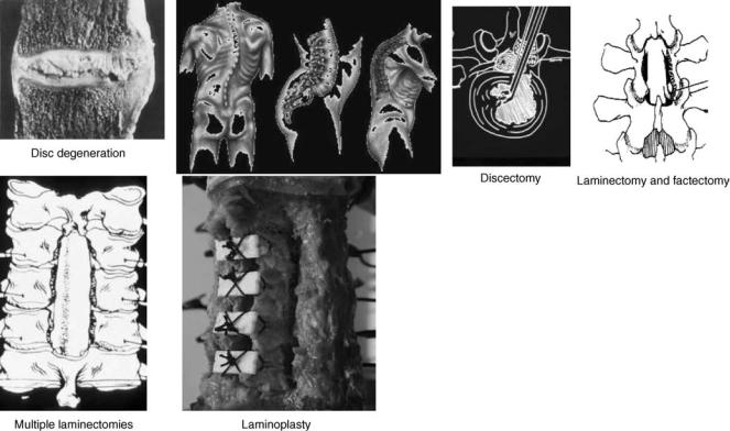
The causes of spinal instability have been hypothesized to include environmental factors that contribute to spinal degeneration and host of other variables (39). For example, some diseases can lead to spinal instability without being the direct cause. Chronic spondylolisthesis can lead to permanent deformation of the annulus that increases the probability of instability, Fig. 7. Essentially, any damage to any of the components of the motion segment or neural elements can contribute to instability. Instability can result from ruptured ligaments, fractured facets, fractured endplates, torn disks, or many other causes. However, the elements within the spine that seem to contribute more to stability and can therefore be major sources of instability are the facet joints, the intervertebral disks, and the ligaments (40). Both in vivo investigations in humans and animals and in vitro investigations of ligamentous spinal segments have been undertaken to accumulate biomechanical data of clinical significance.
Role of Environmental Factors in Producing Instability–Injury
Upper Cervical Spine. High speed impact loads that may be imposed on the spine are one of the major causes of
spinal instability in the cervical region, especially in the upper region. To quantify the likely injuries of the atlas, Oda et al. (39,40) subjected upper cervical spine specimens to high speed axial impact by dropping 3–6 kg weights from various heights. The load produced axial compression and flexion of the specimen. Both bony and soft tissue injuries, similar to Jefferson fractures, were observed. The bony fractures were six bursting fractures, one four-part fracture without a prominent bursting, and one posterior arch fracture. The major soft tissue injury involved the transverse ligament. There were five bony avulsions and three midsubstance tears. The study was extended to determine the three-dimensional (3D) load displacements of fresh ligamentous upper cervical spines (C0-C3) in flexion, extension, and lateral bending before and following the impact loading in the axial mode. The largest increase in flexibility due to the injury was in flexion–extension: 42%. In lateral bending, the increase was on the order of 24%; in axial rotation it was minimal: 5%. These increases in motion are in concordance with the actual instabilities observed clinically. In patients with burst fractures of the atlas, Jefferson noted that the patients could not flex their heads, but could easily rotate without pain (41).
Heller et al. (42) tested the transverse ligament attached to C1 vertebra by holding the C1 vertebra and pushing the ligament in the middle along the AP direction. The specimens were loaded with an MTS testing device at varying loading rates. Eleven specimens failed within the substance of the ligament, and two failed by bone avulsion.
Figure 7. Various spinal disorders and surgical procedures that may lead to spinal instability. Such procedures are common for all of the spine regions.
The mean load to failure was 692 N (range 220–1590 N). The displacement to failure ranged from 2 to 14 mm (mean 6.7 mm). This study, when compared with the work of Oda et al. (39,40) suggests that (a) anteroposterior (AP) translation of the transverse ligament with respect to the dens is essential to produce its fracture; (b) rate of loading affects the type of fracture (bony versus ligamentous) but not the displacement at failure; and (c) even ‘‘axial’’ impact loads are capable of producing enough AP translation to produce a midsubstance tear of the ligament, as reported by Oda et al. (39).
The contribution to stabilization by the alar ligament of the upper cervical spine is of particular interest in evaluation of the effects of trauma, especially in the axial rotation mode. Goel and associates (43), in a study of occipitoatlantoaxial specimens, determined that the average values for axial rotation and torque at the point of maximum resistance were 68.18 and 13.6 N m, respectively. They also observed that the value of axial rotation at which complete bilateral rotary dislocation occurred was approximately the point of maximal resistance. The types of injuries observed were related to the magnitude of axial rotation imposed on a specimen during testing. Soft tissue injuries (such as stretch–rupture of the capsular ligaments, subluxation of the C1-C2 facets) were confined to specimens rotated to or almost to the point of maximum resistance. Specimens that were rotated well beyond the point of maximum resistance also showed avulsion fractures of the bone at the points of attachment of the alar ligament or fractures of the odontoid process inferior to the level of alar ligament attachment. The alar ligament did not rupture in any of the specimens. Chang and associates (44) extended this study to determine the effects of rate of loading (dynamic loading) on the occipitoatlantoaxial complex. The specimens were divided into three groups and tested until failure at three different dynamic loading rates: 508/s, 1008/s, and 4008/s as compared to the quasistatic (48/s) rate of loading used by Goel et al.(43). The results showed that at the higher rates of loading, (a) the specimens became stiffer and the torque required to produce ‘‘failure’’ increased significantly (e.g., from 13.6 N m at 48/s to 27.9 N m at 1008/s); (b) the corresponding right angular rotations (65–798) did not change significantly; and (c) the rates of the alar ligament midsubstance rupture increased and that of ‘‘dens fracture’’ decreased. No fractures of the atlas were noted. This is another example of the rate of load application affecting the type of injury produced.
Fractures of the odontoid process of the second cervical vertebra comprise 7–13% of all cervical spine fractures (45). Most published reports involving odontoid fracture use the classification system detailed by Anderson and D’Alonzo (46). They described three types of odontoid process fracture (Fig. 8). Type I is an oblique fracture near the superior tip of the odontoid process and is thought to involve an avulsion defect associated with the alar–apical complex. Fracture of the odontoid process at the juncture of the process and vertebral body in the region of the accessory ligaments (Type II) is the most common osseous injury of the atlas. Fractures of this type lead to a highly unstable cervicovertebral region, commonly threatening the spinal
HUMAN SPINE, BIOMECHANICS OF |
559 |
TYPE I
TYPE II
TYPE III
Figure 8. Fractures of the odontoid process. Taken from Ref. 46.
canal, and are often accompanied by ligamentous insult. Many of these fractures result in pseudoarthrosis if not properly treated. Type III fractures involve the junction of the odontoid process and the anterior portion of the vertebral body. These fractures are thought to be more stable than the Type I and Type II fractures. Type III fractures have high union rates owing to the cancellous bone involvement and the relatively high degree of vascularity (46,47).
Forces required to produce various types of dens fractures have been documented by Doherty et al. (45) who harvested the second cervical vertebra from fresh human spinal columns. Force was applied at the tip of the dens until failure occurred. The direction of the applied force was adjusted to exert extension bending or combined flexion and lateral bending on the tip of the dens. Extension resulted in type III fractures, and the combined load led to type II fractures of the dens. Furthermore, dynamic loading modes are essential to produce midsubstance ligament ruptures as opposed to dens fractures, especially in a normal specimen. Odontoid fractures have been implicated as being the result of high energy traumatic events. Indeed, there have been numerous accounts as to the events that lead to odontoid fracture. Schatzker et al. (47) reported that 16 of the 37 cases they reviewed were due to motor vehicle accidents and 15 cases were the result of high energy falls. Clark and White (48) report that all Type II (96 patients) and Type III (48 patients) fractures they reviewed were attributable to either motor vehicle accidents ( 70%) or
560 HUMAN SPINE, BIOMECHANICS OF
falls. Alker et al. (19) examined postmortem radiographs of 312 victims of fatal motor vehicle accidents. The cohort exhibited 98 injuries of the cervical spine, of which 70 were seen in the craniovertebral junction. The authors, although not quantifying the degree of dens fractures, hypothesized that odontoid fractures were probably due to hyperextension because of the posterior displacement of the fracture pieces.
There is considerable controversy as to the major load path that causes odontoid fractures. A review of the clinical and laboratory research literature fails to designate a consensus on this issue. Schatzker et al. (47) reviewed clinical case presentations and concluded that odontoid fractures are not the result of simple tension and that there must exist a complex combination of forces needed to produce these failures. Althoff (49) performed a cadaver study, whereby he applied various combinations of compression and horizontal shear to the head via a pendulum. Before load onset the head was placed in neutral, extension or flexion. The position of the load and the angle of impact, determining the degree of compression with shear, was changed for each experiment. The results indicated that an impact in the sagittal plane (anterior or posterior) produced fractures that involved the C2 body (Type III). As the force vector moved from anterior to lateral, the location of the fracture moved superiorly, with lateral loading producing Type I fractures. This led the author to propose a new hypothesis: impact loading corresponding to combined horizontal shear and compression results in odontoid fractures. Althoff dismissed the contributions of sagittal rotation (flexion and extension) to the production of resultant odontoid fracture.
Mouradian et al. (50) reported on a cadaver and clinical model of odontoid fracture. In their opinion, ‘‘it seems reasonable to assume that shearing or bending forces are primarily involved.’’ The cadaver experimentation involved anterior or lateral translation of the occiput as well as lateral translation of the atlantal ring. In forward loading, the odontoid was fractured in 9 of the 13 cases, with 8 Type III fractures and 1 Type II fracture. The lateral loading specimens evidenced similar patterns of odontoid fracture regardless of the point of load application (on the occiput or on the atlas). In 11 specimens, lateral loading resulted in 10 Type II fractures and 1 Type III fracture. The clinical model involved reviewing 25 cases of odontoid fracture. They reported that 80% of these cases resulted from flexion or flexion–rotation injuries. They pointed out that the clinical data does not reflect the lateral loading cadaver experimentation results. In fact, they state that ‘‘a pure lateral blow probably did not occur in any [clinical] case’’. However, their clinical data indicated that the remaining 20% of the odontoid injuries could be ascribed to extension injuries. The technical difficulties precluded cadaver experimentation of this possible mechanism. Experimental investigations dealing with the pathogenesis of odontoid fractures have failed to produce a consensus as to the etiology of these fractures. These findings may actually reflect the diversity of causal mechanisms, suggesting the various mechanical factors are coincident in producing these fractures. It is difficult to diskern if this is the case or if this is due to the inhomogeneity of cadaver
experiment methodology. That is, some of the boundary and loading conditions used by the surveyed studies are vastly different and have produced divergent results. In addition, the anatomical variants of the craniovertebral osteo-ligamentous structures could also be integral to the cadaver study outcomes. The purpose of the study undertaken by Puttlitz et al. (51) was to utilize of the finite element method, in which the loading and kinematic constraints can be exactly designated, for elucidating the true fracture etiology of the upper cervical spine. Previous laboratory investigations of odontoid process failure have used cadaver models. However, shortcomings associated with this type of experimentation and the various loading and boundary conditions may have influenced the resulting data. Utilization of the FE method for the study of odontoid process failure has eliminated confounding factors often seen with cadaveric testing, such as interspecimen anatomic variability, age-dependent degeneration, and so on. This has allowed us to isolate changes in complex loading conditions as the lone experimental variable for determining odontoid process failure.
There are many scenarios, that are capable of producing fracture of the odontoid process. Force loading, in the absence of rotational components, can reach maximum von Mises stresses that far exceed 100 MPa. Most of these loads are lateral or compressive in nature. The maximum stress obtained was 177 MPa due to a force directed in the posteroinferior direction. The net effect of this load vector and its point of application, the posterior aspect of the occiput, is to produce a compression, posterior shear, and extension due to the load’s offset from the center of rotation. This seems to suggest that extension and compression can play a significant role in the development of high stresses, and possibly failure, of the odontoid. The location of the maximum stress for this loading scenario was in the region of a Type I fracture. The same result, with respect to laterally loading, was obtained by Althoff (49). However, he dismissed the contribution of sagittal plane rotation to development of odontoid failures. The results of this study disagree with that finding. Posteroinferior loading with extension produced a maximum von Mises stress in the axis of 226 MPa. As stated above, the load vector for this case intensifies the degree of extension, probably producing hyperextension. The addition of the extension moment did not change the location of the maximum stress, still identifiable in the region of a Type I fracture. The clinical study by Moradian et al. (50) suggested that almost 20% of the odontoid fracture cases they reviewed involved some component of extension. The involvement of extension in producing odontoid process failures can be explained by its position with respect to the atlantal ring and the occiput. As extension proceeds, the contact force produced at the atlanto-dental articulation increases, putting high bending loads on the odontoid process. The result could be failure of the odontoid. Increasing tension of the alar ligaments as the occiput extends could magnify these bending stress via superposition of the loads, resulting in avulsion failure of the bone (Type I).
While the FE model predicted mostly higher stresses with the addition of an extension moment, the model showed that, in most cases, flexion actually mitigates
the osseous tissue stress response. This was especially true for compressive (inferior) force application. Flexion loading with posterior application of an inferior load vectorally decreases the overall effect of producing extension on the occiput. None of the studies surveyed for this investigation pinpointed flexion, per se, as a damage mechanism for odontoid failure. The findings of this study supported the lack of evidence in support of flexion as being a causal mechanism for failure. In addition, the data suggested that flexion can act as a preventative mechanism against odontoid fracture.
Once again, the lateral bending results support the hypothesis of extension being a major injury vector in odontoid process failure. Inferior and posteroinferior loads with lateral rotation resulted in the highest maximal von Mises stress in the axis. Lateral loading also intensified the maximal stress in compression, suggesting rotations that incorporate a component of both lateral and extension motion may cause odontoid failures. Many of the lateral bending scenarios resulted in the maximum von Mises stress being located in the Type II and Type III fracture regions. In fact, the only scenarios that lead to the maximum stress in the Type I area was when there was an inferior or posterior load applied with the lateral bending. This is, again, suggestive that the extension moment, produced by these vectors and their associated moment arms (measured from the center of rotation), can result in more superiorly-located fractures.
Overall, this investigation has indicated that extension and the application of extension via force vector application, causes the greatest risk of superior odontoid failure. The hypothesis of extension as a causal mechanism of odontoid fracture includes coupling of this motion to other rotations. Flexion seems to provide a protective mechanism against force application that would otherwise cause a higher risk of odontoid failure.
Middle and Lower Cervical Spine. In the C2-T1 region of the spine, as in the upper cervical region, instabilities in a laboratory setting have been produced in an effort to understand the dynamics of traumatic forces on the spine (19). In one study, fresh ligamentous porcine cervical spine segments were subjected to flexion-compression, exten- sion-compression, and compression-alone loads at high speeds (dynamic–impact loading) (19). The resultant injuries were evaluated by anatomic dissection. The results that the severity of the injuries were related mostly to the addition of bending moments to high speed axial compression of the spine segment, since compression alone produced the least amount of injury and no definite pattern of injuries could be identified. Other investigators have reported similar results (19).
Lumbar Spine. The onset of low back pain is sometimes associated with a sudden injury. However, it is more often the result of cumulative damage to the spinal components induced by the presence of chronic loading on the spine. Under chronic loading, the rate of damage may exceed the rate of repair by the cellular mechanisms, thus weakening the structures to the point where failure occurs under midly abnormal loads. Chronic loading to structures may
HUMAN SPINE, BIOMECHANICS OF |
561 |
occur under a variety of conditions (52,53). One type of loading is heavy physical work prevalent among blue collar workers. Lifting not only induces large compressive loads across the segment, but tends to be associated with bending and twisting (54). Persons with jobs requiring the lifting of objects of >11.3 kg > 25 times/day have over three times the risk for acute disk prolapse than people whose jobs do not require lifting (55). If the body is twisted during lifting, the risk is even higher with less frequent lifting. The other major class of loading associated with low back pain is posture related, for example, prolonged sitting–sedentary activities, and posture that involve bending over while sitting. Prolonged sitting may be compounded by vibration, such as observed in truck drivers (52,56,57).
The effects of various types of cyclic loads on the specimen behavior have been investigated (52,55). For example, Liu et al. subjected ligamentous motion segments to cyclic axial loads of varying magnitudes until failure or 10,000 cycles, which ever occurred first (53). Test results fell in to two categories, stable and unstable. In the unstable group, fracture occurred within the 6000 cycles of loading. The radiographs in the unstable group revealed generalized trabecular bony microfailure. Cracks were found to propagate from the periphery of the subcondral bone. After the removal of the organic phase, the unstable group specimens disintegrated into small pieces, as opposed to stable group specimens. This suggests that microcrack initiation occurs throughout the inorganic phase of the subchondral bone as a result of axial cyclic loading. In response to cyclic axial twisting of the specimens, Liu et al. noticed a diskharge of synovial fluid from the articular joints (58). Specimens that exhibited an initial angular displacement of <1.58, irrespective of the magnitude of the applied cyclic torque, did not show any failures. On the other hand, specimens, exhibiting initial rotations <1.58, fractured before reaching 10,000 cycles. These fractures included bony failure of facets and/or tearing of the capsular ligaments.
Chronic vibration exposure and prolonged sitting are also known to lead to spinal degeneration. Spinal structures exhibit resonance between 5 and 8 Hz (56–59). In vivo and in vitro experimental and analytical studies have shown that the intradiscal pressure and motion increase when spinal structures experience vibration, such as during driving cars–trucks, at the natural resonant frequency (59). Prolonged sitting alone or in conjunction with chronic vibration exposure is also a contributing factor to spinal degeneration. A finite element-based study revealed that prolonged sitting led to an increase in disk bulge and the stresses in the annulus fibers located at the outer periphery (59,60).
Lee et al. (61) quantatively analyzed occlusion of the dural-sac in the lumbar spine was quantitatively analyzed by utilizing a finite element lumbar spine model. In the static analysis, it was found that < 2 kN of compressive load could not produce dural-sac occlusion, but the compression together with extension moment was more likely to produce the dural-sac occlusion. The 7.4% of occlusion was obtained when the 8 N m of extension moment was added to 2 kN of compressive load that alone did not create any occlusion. The magnitude of occlusions was increased
562 HUMAN SPINE, BIOMECHANICS OF
to 10.5% as the extension moment increased to 10 N m with the same 2 kN of compressive load. In creep analysis, 10 N m extension, kept for 3600 s, induced 6.9% of occlusion, and 2.4% of volume reduction in the dural-sac. However, flexion moment did not produce any occlusion in the duralsac, but increased the volume instead because it caused stretching of the dural-sac coupled with vertebral motion. As a conclusion, occlusions resulted mainly from the slackening of the ligamentum flavum and disk bulging. Furthermore, the amount of occlusion was strongly dependent with loading conditions and the viscoelastic behavior of materials as well.
Changes in Motion due to Degeneration–Trauma
The degenerative process can effect all of the spinal elements and trauma can lead to partial or full destruction of the spinal elements. As such the motion behavior of the segment will change.
Cervical Spine Region. The rotation-limiting ability of the alar ligament was investigated by Dvorak et al. (62,63). A mean increase of 10.88 or 30% (divided equally between the occipitoatlantal and atlantoaxial complexes) in axial rotation was observed in response to an alar lesion on the opposite side. Oda et al. (39,40) determined the effects of alar ligament transections on the stability of the joint in flexion, extension, and lateral bending modes. Their main conclusion was that the motion changes occurred subsequent to alar ligament transection. The increases, however, were directional-dependent. Crisco et al. (64) compared changes in 3D motion of C1 relative to C2 before and after the capsular ligament transections in axial rotation. Two groups of cadaveric specimens were used to study the effect of two different sequential ligamentous transections. In the first group (n ¼ 4), transection of the left capsular ligament was followed by transection of the right capsular ligament. In the second group (n ¼ 10), transection of the left capsular ligament preceded transection of left and right alar and transverse ligaments. The greatest changes in motion occurred in axial rotation to the side opposite the transection. In the first group, transection of left capsular ligaments resulted in a significant increase in axial rotation ROM to the right of 18. After the right capsular ligament was transected, there was a further significant increase of 1.88 to the left and of 1.08 to the right. Lateral bending to the left also increased significantly by 1.58 after both ligaments were cut. In the second group, with the nonfunctional alar and transverse ligaments, transection of the capsular ligament resulted in greater increases in ROM: 3.38 to the right and 1.38 to the left. Lateral bending to the right also increased significantly by 4.28. Although the issue is more complex than this, in general these studies show that the major function of the alar ligament is to prevent axial rotation to the contralateral side. Transection of the ligament increases the contralateral axial rotation by 15%.
The dens and the intact transverse ligament provide the major stability at the C1-C2 articulation. The articular capsules between C1 and C2 are loose, to allow a large amount of rotation and provide a small amount of stability.
Although the C1-C2 segment is clinically unstable after failure of the transverse ligament, resistance against gross dislocation is probably provided by the tectorial membrane, the ala, and the apical ligaments. With transection of the tectorial membrane and the ala ligaments, there is an increased flexion of the units of the occipital–atlantoaxial complex and a subluxation of the occiput (4h). It was also demonstrated that transection of the ala ligament on one side causes increased axial rotation to the opposite side by30%.
Fielding et al. (65) performed a biomechanical study investigating lesion development in rheumatoid arthritis. Their study tested 20 cadaveric occipitoatlanto–axial specimens for transverse ligament strength by application of a posterior force to the atlantal ring. They found atlantoaxial subluxation of 3–5 mm and increased atlas movement on the axis after rupture of the transverse ligament. From this study, Fielding et al. were able to conclude that the ‘‘transverse ligament represents a strong primary defense against anterior shift of the first cervical vertebra.’’ Puttlitz et al. (66) developed an experimentally validated ligamentous, nonlinear, sliding contact 3D finite element (FE) model of the C0-C1-C2 complex generated from 0.5-mm thick serial computed tomography scans (Fig. 9). The model was used to determine specific structure involvement during the progression of RA and to evaluate these structures in terms of their effect on clinically observed erosive changes associated with the disease by assessing changes in loading patterns and degree of AAS (see Table 9 for terminology). The role of specific ligament involvement during the development and advancement of AAS was evaluated by calculating the AADI and PADI after reductions in transverse, ala, and capsular ligament stiffness. (The stiffness of transverse, alar, and capsular ligaments was sequentially reduced by 50, 75, and 100% of their intact values.) All models were subjected to flexion moments, replicating the clinical diagnosis of RA using full flexion lateral plane radiographs. Stress profiles at the transverse ligament-odontoid process junction were monitored. Changes in loading profiles through the C0-C1 and C1-C2 lateral articulations and their associated capsular ligaments were calculated. Posterior atlantodental interval (PADI) values were calculated to correlate ligamentous destruction to advancement of AAS. As an isolated entity, the model predicted that the transverse ligament had the greatest effect on AADI in the fully flexed posture. Without transverse ligament disruption, both ala and capsular ligament compromise did not contribute significantly to the development of AAS. Combinations of ala and capsular ligament disruptions were modeled with transverse ligament removal in an attempt to describe the interactive effect of ligament compromise, which may lead to advanced AAS. Ala ligament compromise with intact capsular ligaments markedly increased the level of AAS (Table 9). Subsequent capsular ligament stiffness loss (50%) with complete ala ligament removal led to an additional decrease in PADI of 0.92 mm. Simultaneous resection of the transverse, ala, and capsular ligaments resulted in a highly unstable situation. The model predicted stresses at the posterior base of the odontoid process greatly reduced, with transverse ligament compromise beyond 75%
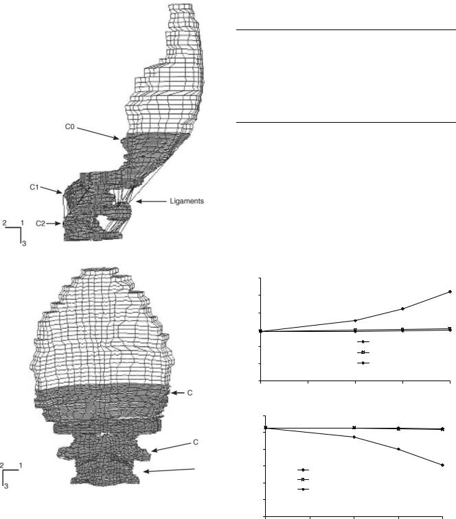
Figure 9. Finite element models of the upper cervical spine used to study the biomechanics of rheumatoid arthritis. (Taken from Ref. 66.)
(Fig. 10). Decreases through the lateral C0-C1 and C1-C2 articulations were compensated by their capsular ligaments. The data indicate that there may be a mechanical component (in addition to enzymatic degradation) associated with the osseous resorption seen during RA. Specifically, erosion of the base of the odontoid may involve Wolff’s law unloading considerations. Changes through
HUMAN SPINE, BIOMECHANICS OF |
563 |
Table 9. Combinations of Ligament Stiffness Reductions with the Resultant Degree of AAS, as Indicated by the AADI and PADI Values at Full Flexion (1.5 N m moment)a
Reduction in Ligament Stiffness, % |
|
Criteria, mm |
||||
|
|
|
|
|
|
|
Transverse |
Alar |
Capsular |
AADI |
PADI |
||
|
|
|
|
|
|
|
0 |
0 |
0 |
|
2.92 |
15.28 |
|
100 |
0 |
50 |
|
5.77 |
12.43 |
|
100 |
0 |
75 |
|
6.21 |
11.99 |
|
100 |
50 |
0 |
|
7.42 |
10.79 |
|
100 |
75 |
0 |
|
7.51 |
10.71 |
|
100 |
100 |
50 |
|
8.43 |
9.83 |
|
aZero (0) ligament stiffness values represent completely intact ligament stiffness, ‘‘100’’ corresponds to total ligament destruction (via removal). (Taken from Ref. 66.) AAS ¼ anterior atlantoaxial subluxation, AADI ¼ anterior atlantodental interval, PADI ¼ posterior atlantodental interval.
the lateral aspects of the atlas suggest that this same mechanism may be partially responsible for the erosive changes seen during progressive RA. The PADI values indicate that complete destruction of the transverse ligament coupled with alar and/or capsular ligament compromise exist if advanced levels of AAS are present.
|
6 |
|
|
|
5 |
|
|
(mm) |
4 |
|
|
3 |
|
||
AADI |
|
||
2 |
Transverse |
||
|
|||
|
Alar |
||
|
|
||
|
1 |
Capsular |
|
0 |
|
|
|
|
|
0 |
25 |
50 |
75 |
100 |
|
|
Reduction in ligament stiffness (%) |
|
||
|
16 |
|
|
|
|
|
15 |
|
|
|
|
(mm) |
14 |
|
|
|
|
13 |
Transverse |
|
|
|
|
PADI |
|
|
|
||
|
|
|
|
||
12 |
Alar |
|
|
|
|
|
Capsular |
|
|
|
|
|
|
|
|
|
|
|
11 |
|
|
|
|
|
10 |
|
|
|
|
|
0 |
25 |
50 |
75 |
100 |
|
|
Reduction in ligament stiffness (%) |
|
||
Figure 10. (a) Anterior atlantodental interval (AADI) (b) and posterior atlantodental interval (PADI) calculated for the intact model and models with stiffness reductions of the transverse, alar, and capsular ligaments at the fully flexed posture (1.5 N m moment load). Each ligament’s stiffness was altered while holding the other two at the baseline value (completely intact). (Taken from Ref. 66.)
564 HUMAN SPINE, BIOMECHANICS OF
In vitro studies to determine the feasibility of the ‘‘stretch test’’ in predicting instability of the spine in the cervical region were performed by Panjabi et al. (67). Four cervical spines (C1-T1; ages 25–29) were loaded in axial tension in increments of 5 kg to a maximum of one third of the specimen’s body weight. The effects of sequential AP transection of soft tissues of a motion segment on the motion in one group and of posterior–anterior transections in another group were investigated. The intact cervical spine went into flexion under axial tension. Anterior transection produced extension. Posterior transection produced opposite results. Anterior injuries creating displacements of 3.3 mm at the disk space (with a force equal to one-third body weight) and rotation changes of 3.88 were considered precursors to failure. Likewise, posterior injuries resulting in 27 mm separation at the tips of the spinous process and an angular increase of 308 with loading were considered unstable. This work supports the concept that spinal failure results from transection of either all the anterior elements or all the posterior plus at least two additional elements.
In a study by Goel et al. (68,69), the 3D load-displace- ment motion of C4-C5 and C5-C6 as a function of transection of C5-C6 ligaments was determined. Transection was performed posteriorly, starting with the supraspinous and interspinous ligaments, followed by the ligamentum flavum and the capsular ligaments. With the transection of the capsular ligaments, the C5-C6 motion segment (injured level) showed a significant increase in motion in extension, lateral bending, and axial rotation. A significant increase in flexion resulted when the ligamentum flavum was transected.
A major path of loading in the cervical spine is through the vertebral bodies, which are separated by the intervertebral disk. The role of the cervical intervertebral disk has received little attention. A finite element model of the ligamentous cervical spinal segment was used to compute loads in various structures in response to clinically relevant loading modes (70). The objective was to predict biomechanical parameters, including intradiskal pressure, tension in ligaments, and forces across facets that are not practical to quantify with an experimental approach. In axial compression, 88% of the applied load passed through the disk. The interspinal ligament experienced the most strain (29.5% in flexion, and the capsular ligaments were strained the most (15.5% in axial rotation). The maximum intradiskal pressure was 0.24 MPa in flexion with an axial compression mode (1.8 N m of flexion moment þ 73.6 N of compression). The anterior and posterior disk bulges increased with an increase in axial compression (up to 800 N). The results provide new insight into the role of various elements in transmiting loads.
This model was further used to investigate the biomechanical significance of uncinate processes and Luschka joints (71). The results indicate that the facet joints and luschka joints are the major contributors to coupled motion in the lower cervical spine and that the uncinate processes effectively reduce motion coupling and primary cervical motion (motion in the same direction as load application), especially in response to axial rotation and lateral bending loads. Luschka joints appear to increase primary cervical
motion, showing an effect on cervical motion opposite to that of the uncinate processes. Surgeons should be aware of the increase in motion accompanied by resection of the uncinate processes.
Cervical spine disorders such as spondylotic radiculopathy and myelopathy are often related to osteophyte formation. Bone remodeling experimental–analytical studies have correlated biomechanical responses, such as stress and strain energy density, to the formation of bony outgrowth. Using these responses of the spinal components, a finite element study was conducted to investigate the basis for the occurrence of disk-related pathological conditions. An anatomically accurate and validated intact element model of the C4-C5-C6 cervical spine was used to simulate progressive disk degeneration at the C5-C6 level. Slight degeneration included an alteration of material properties of the nucleus pulposus representing the dehydration process. Moderate degeneration included an alteration of fiber content and material properties of the annulus fibrosus representing the disintegrated nature of the annulus in addition to dehydrated nucleus. Severe degeneration included decrease in the intervertebral disk height with dehydrated nucleus and disintegrated annulus. The intact and three degenerated models were exercised under compression, and the overall force-displa- cement response, local segmental stiffness, annulus fiber strain, disk bulge, annulus stress, load shared by the disk and facet joints, pressure in the disk, facet and uncovertebral joints, and strain energy density and stress in the vertebral cortex were determined. The overall stiffness (C4-C6) increased with the severity of degeneration. The segmental stiffness at the degenerated level (C5-C6) increased with the severity of degeneration. Intervertebral disk bulge and annulus stress and strain decreased at the degenerated level. The strain energy density and stress in vertebral cortex increased adjacent to the degenerated disk. Specifically, the anterior region of the cortex responded with a higher increase in these responses. The increased strain energy density and stress in the vertebral cortex over time may induce the remodeling process according to Wolff’s law, leading to the formation of osteophytes.
Thoracolumbar Region. The most common vertebral levels involved with the thoracolumbar injuires are T12L1 (62%) and L1-L2 (24%) (22,25). The injuires, depending on the severity of the trauma, have included disruption of the posterior ligaments, fracture and dislocation of the facets, and fracture of the vertebral bodies with and without neural lesions. Operative intervention is often suggested to restore spinal stability. These involve use of spinal instrumentation, vertebroplasty, and host of other procedures which have been described elsewhere in this article.
For ease in description of these injuries, conceptually the osteoligamentous structures of the spine have been grouped into three ‘‘columns’’; anterior, middle, and posterior. The anterior column consists of the anterior longitudinal ligament, anterior annulus fibrosus, and the anterior part of the vertebral body. The middle column consists of the posterior longitudinal ligament, posterior annulus
fibrosus, and the posterior vertebral body wall. The posterior column contains the posterior bony complex or arch (including the facet joints), and the posterior ligamentous complex composed of the supraspinous ligament, interspinous ligament, facet joint capsules, and ligamentum flavum.
As per this classification, a compression fracture is a fracture of the anterior column with the middle and posterior columns remaining intact. In severe cases, there may also be a partial tensile failure of the posterior column, but the vertebral ring, consisting of the posterior wall, pedicles, and lamina, remains totally intact in a compression fracture. A burst fracture is a fracture of the anterior and middle columns under compression; the status of the posterior column can vary. In the burst fracture, there is fracture of the posterior vertebral wall cortex with marked retropulsion of bone into the spinal canal, obstructing, on average, 50% of the spinal canal cross-section. There may be a tilting and retropulsion of a bone fragment into the canal from one or both endplates. In contrast to the compression fracture, there is loss of posterior vertebral body height in a burst fracture. The seat-belt type injuries feature failure of the middle and posterior columns under tension, and either no failure or slight compression failure of the anterior column. In fracture dislocations, the anterior, middle, and posterior columns all fail, leading to subluxation or dislocation. There may be ‘‘jumped facets’’ or fracture of one articular process at its base or at the base of the pedicle. There is also disruption of the anterolateral periosteum and anterior longitudinal ligament. If the separation goes through the disk, there will be some degree of wedging in the vertebral body under the disk space. However, the fracture cleavage may pass through the vertebral body itself, resulting in a ‘‘slice fracture’’.
There are four mechanisms of fracture that have been hypothesized in the literature to explain why the thoracolumbar region experiences a higher frequency of injury than adjacent regions. The hypotheses state that a thoracolumbar fracture sequence can be put into motion by stress concentrations arising from (1) spinal loading conditions; (2) material imperfections in spine; (3) differences in spinal stiffness and physiological range of motion characteristics between the thoracic and lumbar regions; and (4) abrupt changes in spinal anatomy, especially facet orientations. As always, there is no conseus for these mechanisms.
A few of the experimental investigations that have attempted to reproduce the clinical fracture patterns are as follows: In one study, cadaver motion segments were subjected to loads of different magnitude and direction: compression, flexion, extension, lateral flexion, rotation, and horizontal shear to reproduce all varieties of spinal injury experimentally by accurately controlled forces. For a normal disk, increases of intradiskal pressure and bulging of the annulus occur under application of axial compressive load. With increased application of force, the end-plate bulges and finally cracks, allowing displacement of nuclear material into the vertebral body. Continued loading of the motion segment results in a vertical fracture of the vertebral body. If a forward shear component of force accompanies the compression force, the line of fracture of the
HUMAN SPINE, BIOMECHANICS OF |
565 |
vertebral body is not vertical but is oblique. Different forms of fracture could be produced by axial compressive loading if the specimens were from older subjects (i.e., the nucleus was no longer fluid), or if the compressive loading was asymmetrical. Under these conditions, the transmission of load mainly through the annulus is responsible for the (1) tearing of the annulus, (2) general collapse of the vertebra due to buckling of the sides (cortical wall), and (3) marginal plateau fracture.
Thoracolumbar burst fractures in cadaver specimens have also been produced by dropping a weight such that the prepared column is subjected to axial-compressive impact loads. The potential energies of the failing weights used by these researchers have been 200 and 300 N m. Fracture in four of the seven specimens apparently started at the nutrient foramen. The nutrient foramen may perhaps be viewed as a local area of material imperfection where stresses may be concentrated during loading, leading to fracture. Other researchers are apparently unable to consistently produce burst fractures in vitro without first creating artificial ‘‘stress raisers’’ in the vertebral body by means of cuts or slices into the bone.
Panjabi et al. (3) conducted in vitro flexibility tests of 11 T11-L1 specimens to document the 3D mechanical behavior of the thoracolumbar junction region (see section on Construct Testing for an explanation). Pure moments up to 7.5 N m were applied to the specimens in flexion–exten- sion, left–right axial torque, and right–left lateral bending. The authors reported the average flexibility coefficients of the main motions (range of motion divided by the maximum applied load). For extension moment, the average flexibility coefficient of T11-T12. (0.328/N m) was significantly less than that of T12-L1 (0.528/N m). For axial torque, the average flexibility coefficient of T11-T12 (0.248/N m) was significantly greater than that of T12-L1 (0.168/N m). The authors attributed these biomechanical differences to the facet orientation. They speculated that thoracic-type facets would offer greater resistance to extension than the more vertically oriented lumbar-type facets while the lumbar-type facets would provide a more effective stop to axial rotation than thoracic-type facets. No other significant biomechanical differences were detected between T11-T12 and T12-L1. In addition to these observations, authors found that for flexion torque, the average flexibility coefficients of the lumbar spine (e.g., L1-L2, 0.588/N m; L5-S1, 1.008/N m) were much greater than those of both T11-T12 (0.368/N m) and T12-L1 (0.398/ N m). They identified this change in flexion stiffness between the thoracolumbar and lumbar regions as a possible thoracolumbar injury risk factor.
Lumbar Spine Region. The porosity of the cancellous bone within the vertebral body increases with age, especially in women. The vertebral body strength is known to decrease with increase in porosity of the cancellous bone, a contributing factor to the kyphosis normally seen in an elderly person (4). As the trabeculae reduce in size and number, the cortical shell must withstand greater axial load, thus increasing the thickness of the shell obeying the principles of Wolff’s law. Edwards et al. (72) demonstrated cortical shell thickening of osteoporotic vertebral bodies
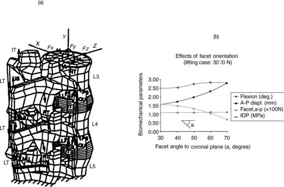
566 HUMAN SPINE, BIOMECHANICS OF
compared to that of normal vertebral bodies. Furthermore, there was increased incidence of osteophytic development along the cortical shell in the regions of highest stress within the compromised osteoporotic vertebrae.
The normal disk consists of a gel-like nucleus encased in the annulus. In a normal healthy person, the disk acts like a fluid filled cavity. With age, the annulus develops radial, circumferential and rim lesions, and the nucleus becomes fibrous. Using a theoretical model in which cracks of varying lengths were simulated, Goel et al. found that the interlaminar shear stresses (and likewise displacements) were minimal until the crack length reached 70% of the annulus depth (73). Likewise, dehydration of the nucleus (extreme case totally ineffective like in a total nucleotomy) also was found to lead to separation of the lamina layers and an increase in motion (74). Thus, the results support the observation that the increase in motion really occurs in moderately degenerated disks.
Posner et al. investigated the effects of transection of the spinal ligaments on the stability of the lumbar spine (75). The ligaments were transected in a sequential manner, either anterior to posterior or posterior to anterior. While cutting structures from the anterior to posterior portion of the spine, extension loading caused a significant residual deformation after the anterior half of the disk was cut. Cutting from the posterior to anterior region, flexion loading caused significant residual motion upon facet joint transection. The role of ligaments becomes more prominent in subjects whose muscles are not fully functional. Using a
finite element model in which the muscular forces during lifting were simulated, Kong et al. found that a 10% decrease in the muscle function increased loads borne by the ligaments and the disks (76). The forces across the facet joint decreased.
The orientation of facet becomes more parallel to the frontal plane as one goes down from L1 to S1 (77). Other factors can also contribute to changes in facet orientation in a person. The facet orientation, especially at L4-5 and L5-S1, plays a role in producing spondylolisthesis. Kong et al. using a finite element of the ligamentous lumbar segment (Fig. 11a) found that as the facet orientation becomes more sagittal, the A–P translation across the segment, increases in response to the load applied, Fig. 11b. The increase in flexion angle was marginal.
Changes in Motion Due to Surgical Procedures
Cervical Region. In vivo ‘‘injuries’’ result in disk degeneration and may produce osteophytes, ankylosed vertebras, and changes in the apophyseal joints (78). The effects of total diskectomy on cervical spine motions are of interest (79). Schulte and colleagues reported a significant increase in the motion after C5-C6 diskectomy (80). Motion between C5-C6 increased in flexion (66.6%), extension (69.5%), lateral bending (41.4%), and axial rotation (37.9%). In previous studies, Martins (81) and Wilson and Campbell (82) could not detect increases in motion roentgenographically and deemed the spines functionally stable.
Figure 11. The finite element of a lumbar segment used to predict the effect of facet orientations on the motion and loads in various spinal components in a motion segment. (Taken from Ref. 77.)
The reasons for this diskrepancy in results are not apparent. The experimental designs were quite different as were the methods of motion measurement. However, the disk obviously is a major structural and functional component of the cervical spine.
The contribution of facet and its capsule to the stability of the cervical spine has been well documented using both in vitro laboratory models (83–85) and mathematical models (70,86,87,88). Facet joints play an integral part in the biomechanical stability of the cervical spine. Cusick et al. (89) found that total unilateral and bilateral facetectomies decreased compression-flexion strength by 31.6 and 53.1%, respectively. Facetectomy resulted in an anterior shift of the IAR, resulting in increased compression of the vertebral body and disk. This work confirmed the findings of Raynor et al. (63,64) who reported that bilateral facetectomy of as much as 50% did not significantly decrease shear strength; however, with a 75% bilateral facetectomy, a significant decrease in shear strength was noted. One should take great care when exposing an unfused segment to limit facet capsule resection to < 50%. With resection of >50% of the capsule, postoperative hypermobility can occur and may require stabilization.
In contrast, studies that focused on the effects of laminectomy alone have been few and still unclear. Goel et al. were the first to evaluate the effects of cervical laminectomy with in vitro spine models (83,90). They found 10% increase of motion in flexion-extension using 0.3 N m after a two level laminectomy. Zdeblick et al. did not find motion changes in flexion–extension after one level laminectomy under 5 N m (84,85). Cusick et al. successfully showed that three level cervical laminectomy (C4-C6) induces a significant increase in total column flexibility using physiologic compression-flexion forces (86,87). Nevertheless, it seems difficult to estimate the instantaneous combination of physiologic compression and flexion forces. Therefore, quantitative evaluation might be difficult with this model. Our results indicate significant increase of spinal column motion in flexion (24.5%), extension (19.1%), and axial rotation (23.7%) using 1.5 N m after a four level (C3-C6) laminectomy. Cervical vertebral laminae may transmit loads. Laminectomies result in the removal of part of this loading path and the attachment points for the ligamentum flavum, interspinous ligament, and the supraspinous ligament. It is not surprising that total laminectomy results in significant modifications in the motion characteristics of the cervical spine, especially in children. For example, Bell et al. (91) reported that multiple-level cervical laminectomy can lead to increase in postoperative hyperlordosis or kyphosis in children. However, there was no correlation between diagnosis, sex, location, or number of levels decompressed and the subsequent development of deformity. Postlaminectomy spinal deformity in the cervical spine, however, is rare in adults, probably owing to stiffening of the spine with age and changes in facet morphology. Goel et al. (89) removed the laminae of multisegmental cervical spines (C2-T2) at the level of C5 and C6 (total laminectomy); in flexion–extension mode, demonstrating an increase in motion of 10%.
In another in vitro study, the effects of multilevel cervical laminaplasty (C3-C6) and laminectomy with
HUMAN SPINE, BIOMECHANICS OF |
567 |
increasing amounts of facetectomy (25% and more) on the mechanical stability of the cervical spine were investigated (88). Cervical laminaplasty was not significantly different from the intact control, except for producing a marginal increase in axial rotation. However, cervical laminectomy with facetectomy of 25% or more resulted in a highly significant increase in cervical motion as compared with that of the intact specimens in flexion, extension, axial rotation, and lateral bending. There was no significant change in the coupled motions after either laminaplasty or laminectomy. The researchers recommended that concurrent arthrodesis be performed in patients undergoing laminectomy accompanied by >25% bilateral facetectomy. Alternatively, one may use laminaplasty to achieve decompression if feasible. More recently, the effect of laminaplasty on the spinal motion using in vivo testing protocols have also been investigated (92–94). Kubo et al. (95) undertook an in vitro 3D kinematic study to quantify changes after a double door laminoplasty. Using fresh cadaveric C2-T1 specimens, sequential injuries were created in the following order: intact, double door laminoplasty (C3-C6) with insertion of hydroxyapatite (HA) spacers, laminoplasty without spacer, and laminectomy. Motions of each vertebra in each injury status were measured in six loading modes: flexion, extension, right and left lateral bending, and right and left axial rotation. Cervical laminectomy showed significant increase in motion compared to intact control in flexion (25%: P <0.001), extension (19%: P <0.05), and axial rotation (24%: P <0.001) at maximum load. Double door laminoplasty with HA spacer indicated no significant difference in motion in all loading modes compared to intact. Laminoplasty without spacer showed intermediate values between laminoplasty with spacer and laminectomy in all loading modes. Initial slack of each injury status showed similar trends that of maximum load although mean % changes of laminectomy and laminoplasty without spacer were greater than that of maximum load. Double door laminoplasty with HA spacer appears to restore the motion of the decompressed segment back to its intact state in all loading modes. The use of HA spacers well contribute to maintain the total stiffness of cervical spine. In contrast, laminectomy seems to have potential leading postoperative deformity or instability.
Kubo et al. (96) undertook another study with the aim to evaluate the biomechanical effects of multilevel foraminotomy and foraminotomy with double door laminoplasty as compared to foraminotomy with laminectomy. Using fresh human cadaveric specimens (C2-T1), sequential injuries were created in the following order: intact, bilateral foraminotomies (C3/4, C4/5, C5/6), laminoplasty (C3-C6) using hydroxyapatite spacer, removal of the spacers, and laminectomy. Changes in the rotations of each vertebra in each injury status were measured in six loading modes: flexion–extension, right–left lateral bending, and right–left axial rotation. Foraminotomy alone, and following laminoplasty showed no significant differences in motion compared to the intact with the exception of axial rotation. After removal of the spacers and following a laminectomy, the motion increased significantly in flexion and axial rotation. The ranges of initial slack showed similar trends when compared to the results at
568 HUMAN SPINE, BIOMECHANICS OF
maximum load. Clinical implications of these observations are presented.
Lumbar Region. The spine is naturally shaped to properly distribute and absorb loads, therefore, any surgical technique involving dissection of spinal components can disrupt the natural equilibrium of the spinal elements and lead to instability. The amount and origin of pain within the spine usually determines the type of surgical procedure for a patient. Such procedures include the removal of some or all of the laminae, facets, and/or disks. A certain increase in the range of motion within the spine can be attributed to each procedure. The increased range of motion can also lead to more pain, as noted by Panjabi and others, who used an external fixator to stabilize the spine (97,98). The fixator decreased the range of motion for flexion, extension, lateral bending, and axial rotation. The pain experienced by the patients who had the external fixator applied was significantly reduced. For these reasons, it is essential to learn the effects of various surgical procedures on the stability of the spine. In particular, we need to consider when procedures may lead to increase in motion to a point leading to instability.
Much of the debate surrounding laminectomy and instability involves the use of fusion after the laminectomy. The possibility that fusion will be necessary to stabilize the spine after a laminectomy is largely case specific and depends on the purpose of the surgery. In a study by Goel et al. , the results did not indicate the presence of instability after a partial laminectomy (99).
The facets are particularly important because they contribute to strength and resist axial rotation and extension. Subsequently, facetectomies can potentially be linked to instability. Abumi et al. developed some conclusions regarding partial and total facetectomies (2). They found that, although it significantly increased the range of motion, a partial facetectomy of one or both facets at a single level did not cause spinal instability. However, the loss of a complete facet joint on one or both sides was found to contribute to instability. Total facetectomy produced an increase of 65% in flexion, 78% in extension, 15% in lateral bending, and 126% in axial rotation compared with intact motion. Goel et al. also found similar results regarding partial facetectomy (99). Another study indicated that facetectomy performed within animals resulted in a large decrease in motion in vivo even though the increase in range of motion occurred acutely (2).
Goel et al. reported a significant increase in the range of motion for all loading modes except extension when a total diskectomy was performed across L4-5 level (99). A significant, but smaller increase in range of motion for subtotal disk removal was also observed, however, the postoperative instability was minimal. Both partial and total diskectomies produced a significant amount of intervertebral translational instability in response to left lateral bending at the L3-L4 and L4-L5 levels. They attributed the one-sided instability to the combination of injuries to the annulus and the right capsular ligament. Studies have also shown that more significant changes to the motion of the spine occur with removal of the nucleus pulposus as opposed to the removal of the annulus (4d). Discectomy
by fenestration and minimal resection of the lamina did not produce instability either.
BIOMECHANICS OF STABILIZATION PROCEDURES
Stability (or instability) retains a central role in the diagnosis and treatment of patients with back pain. Several studies have been carried out that help to clarify the foundation for understanding stability in the spine, as summarized above. In recent years, to restore stability across an abnormal segment, surgeons have well-accepted surgical stabilization and fusion of the spine using instrumentation, Figs. 12 and 13. The types and complexity of procedures (e.g., posterior, anterior, interbody) (100–105) have produced novel design challenges, requiring sophisticated testing protocols. In addition, most contemporary implant issues of stabilization and fusion of the spine are mostly mechanical in nature. [Biologic factors related to the adaptive nature of living tissue further complicate mechanical characterization (103,105)] Accordingly, it becomes essential to understand the biomechanical aspects of various spinal instrumentation and their effectiveness in stabilizing the segment. Properly applied spinal instrumentation maintains alignment and shares spinal loads until a solid, consolidated fusion is achieved. With few exceptions, these hardware systems are used in combination with bone grafting procedures, and may be augmented by external bracing systems.
Spinal implants typically follow loosely standardized testing sequelae during the design and development stage and in preparation for clinical use. The design and development phase goal, from a biomechanical standpoint, seeks to characterize and define the geometric considerations and load-bearing environment to which the implant will be subjected. Various testing modalities exist that elucidate which components may need to be redesigned. Not including the testing protocols for individual components of a device, plastic vertebrae (corpectomy) models are one of the first-stage tests that involves placing the assembled device on plastic vertebral components in an attempt to pinpoint which component of the assembled device may be the weakest mechanical link in the worst-case scenario, vertebrectomy. The in vivo effectiveness of the device may be limited by its attachment to the vertebras (fixation). Thus, testing of the implant-bone interface is critical in determining the fixation of the device to biologic tissue. Construct testing on cadaveric specimens provides information about the effectiveness of the device in reducing intervertebral motion across the affected and adjacent segments during quasiphysiologic loading. Animal studies provide insight with respect to the long-term biologic effects of implantation. Analytic modeling, such as the finite element method, is an extremely valuable tool for determining how implants and osseous loading patterns change with varying parameters of the device design. This type of modeling may also provide information about temporal changes in the bone quality due to the changing loading patterns as bone adapts to the implant (e.g., stress shielding-induced bone remodeling). After a certain level of confidence in the implant’s safety and effectiveness is
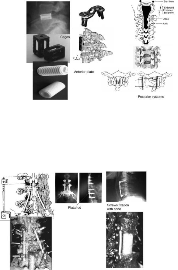
HUMAN SPINE, BIOMECHANICS OF |
569 |
Figure 12. Devices used for stabilizing the cervical spine using the anterior and posterior approaches. Cages used both for the lumbar and cervical regions are also shown.
established via all or some of the aforementioned tests, controlled clinical trials allow for the determination of an implant’s suitability for widespread clinical use. The following sections discuss each of these testing modalities, with specific examples used to illustrate the type of information that different tests can provide.
Implant–Bone Interface
Depending on the spinal instrumentation, the implant-bone interface may deal with the interface, where the spinal
instrumentation abuts, encroaches, or invades the bone surface. It may include bony elements, such as the laminas, pedicles, the vertebral body itself, or the vertebral endplates.
Interlaminar Hooks. Interlaminar hooks are used as a means for fixing the device to the spine. Hook dislodgment, slippage, and incorrect placement have led to loss of fixation, however, resulting in nonfusion and pseudoarthrosis. Purcell et al. (106) investigated construct stiffness as a function of hook placement with respect to affected level in a thoracolumbar cadaver model. The failure moment was
Figure 13. Examples of spinal instrumentation used in the lumbar region. Figure on the bottom right is an anterior plate.
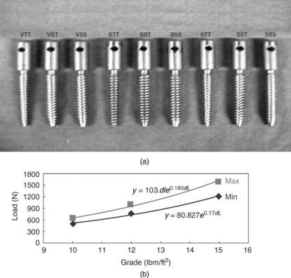
570 HUMAN SPINE, BIOMECHANICS OF
found to be a function of the location of the hook placement with regard to the ‘‘injured’’ vertebra. The authors recommended hook placements three levels above and two levels below the affected area. This placement reduced vertebral tilting (analogous to intervertebral motion) across the stabilized segment, where fusion is to be promoted. Furthermore, the three-above, two-below surgical instrumentation strategy avoids the construct ending at the apex of a spinal deformity. Shortened fixation in this manner tends to augment a kyphotic deformity and cause continued progressive deformation. Overall, the use of hook fixation is a useful surgical stabilization procedure in patients with poor bone quality, where screw fixation is not an ideal choice for achieving adequate purchase into the bone.
Transpedicular Screws. Proper application of screw based anterior or posterior spinal devices requires an understanding of screw biomechanics, including screw characteristics and insertion techniques, as well as an understanding of bone quality, pedicle and vertebral body morphometries, and salvage options (107–109). This is best illustrated by the fact that the pedicle, rather than the vertebral body, contributes 80% of the stiffness and60% of the pull out strength across the screw–bone interface (107).
Carlson et al. (110) evaluated the effects of screw orientation, instrumentation, and bone mineral density on screw translation, rotation at maximal load, and compliance of the screw–bone interface in human cadaveric bones. An inferiorly directed load was applied to each screw, inserted either anteromedially or anterolaterally,
until failure of the fixation was perceived. Anteromedial screw placement with fully constrained loading linkages provided the stiffest fixation at low loads and sustained the highest maximal load. Larger rotation of the screws, an indication of screw pull out failure, was found with the semi-constrained screws at maximal load. Bone mineral density directly correlated with maximal load, indicating that bone quality is a major predictor of bone–screw interfacial strength. A significant correlation between BMD and insertional torque (p <0.0001, r ¼ 0.42), BMD and pullout force (p < 0.0001, r ¼ 0.54), and torque and pullout force has been found (109–112).
Since the specimens used for pull-out strength studies primarily come from elderly subjects, Choi et al. used foams of varying densities to study the effect of bone mineral density on the pull out strength of several screws (112). Pedicle screws (6.0 40 mm, 2 mm pitch, Ti alloy) of several geometric variations used for the study included the buttress (B), square (S), and V-shape (V) screw tooth profiles. For each type of tooth profile, its core shape (i.e., minor diameter) also varied, either the straight (i.e., cylindrical, core diameter ¼ 4.0 mm) or tapered (i.e., conical, core diameter ¼ 4.0/2.0 mm). In addition, for the cylindrical screws the major diameter was kept straight or tapered. The conical screws had its major diameters tapered only. Therefore, screws with a total of nine different geometries were prepared and tested (Fig. 14a). The screws were implanted in the rigid polyurethane foams of three different grades. The pullout strengths for various screw designs are shown in Table 10. The highest purchasing power in any screw design was observed in foams with
Figure 14. (a) Types of screws used in the foam model to determine the pull-out strength. The nomenclature used is as follows: Square ¼ S, Buttress ¼ B, V-shape ¼ V. Screw diameters were
SS ¼ straight |
major |
diameter |
on |
straight |
core, |
ST ¼ straight |
major |
diameter |
on |
tapered |
core, |
TT ¼ tapered major diameter on tapered core.
(b) Regression analysis. The maximum and minimum values from pull-out test for each foam grade were used regardless of tooth or core profiles. (Taken from Ref. 112.)

HUMAN SPINE, BIOMECHANICS OF |
571 |
Table 10. Axial Pull Out Strength (N) Data for Different Types of Screws, Based on a Foam Model of Varying Densities
|
|
|
|
|
Tooth Profile(Mean SD) |
|
|
|
Foam Grade |
Body Profile |
|
Square |
Buttress |
V-shape |
|||
|
|
|
|
|
|
|
|
|
10 |
SSa |
591 |
22 |
497 |
80 |
615 |
36 |
|
|
STb |
622 |
43 |
598 |
25 |
634 |
19 |
|
|
TTc |
525 |
36 |
547 |
30 |
568 |
74 |
|
12 |
SS |
864 |
50 |
769 |
56 |
987 |
55 |
|
|
ST |
956 |
30 |
825 |
108 |
1005 |
92 |
|
|
TT |
811 |
41 |
808 |
25 |
944 |
32 |
|
15 |
SS |
1397 |
93 |
1303 |
126 |
1516 |
78 |
|
|
ST |
1582 |
82 |
1438 |
36 |
1569 |
79 |
|
|
TT |
1197 |
43 |
1352 |
88 |
1396 |
68 |
|
aStraight major diameter on Straight core. bStraight major diameter on Tapered core.
cTapered major diameter on Tapered core. (Taken from Ref. 112.)
the highest density (Grade 15). Exponential increase in pullout strength was seen when the foam density increased from Grade 10–15 (Fig. 14b). Overall, results demonstrated that the conical screws were consistently more effective against the pullout than the cylindrical designs. This was especially evident when the major diameter of the screw was kept straight. In this case, the contact area between the screw thread and surrounding foam was large. Although no consistent statistical superiority was found with the tooth profiles, results did suggest that the V-shape tooth screws ranked highest in many statistical comparisons and the buttress types showed comparatively lower pullout strength than the other types. This finding may be somewhat different from the literature. This can be due to the absence of the cortical purchase in the foam model used in this study. On the other hand, the square-tooth screws faired well in terms of pullout strength when the major diameter was kept straight but did not do so when tapered. Results also suggested that as the density of host site was decreased no clear choice of tooth profile could be found.
Lim et al. investigated the relationship between the bone mineral density of the vertebral body and the number of loading cycles to induce loosening of an anterior vertebral screw (113). (Screw loosening was defined as 1 mm displacement of the screw relative to bone). The average number of loading cycles to induce screw loosening was significantly less for specimens with bone mineral density <0.45 g cm 2, compared to those with bone mineral density > or ¼ 0.45 g cm 2. These findings suggest that bone mineral density may be a good predictor of anterior vertebral screw loosening as well, just like the pedicle screws.
Since BMD seems to play a crucial role in the loosening of fixation screws, their use with osteoporotic bone is a contraindication. Alternatives have been proposed, including the use of bone cement to augment fixation and use of hooks along with pedicle screws (114,115).
The above findings related to increased pullout strength, number of cycles to failure, and tightening torque with BMD, are not fully corroborated with the corresponding in vivo work. For example, moments and forces during pedicle screw insertion were measured in vivo and in vitro and correlated to bone mineral density, pedicle size, and other screw parameters (material, diameter) (116). The mean in vivo insertion torque (1.29 N m) was significantly
greater than the in vitro value (0.67 N m). The linear correlation between insertion torque and bone mineral density was significant for the in vitro data, but not for the in vivo data. No correlation was observed between insertion torque and pedicle diameter. However, another investigation that clinically evaluated 52 patients who underwent pedicle screw fixation augmenting posterior lumbar interbody fusion (PLIF) supports the in vitro findings. The BMD was measured using DEXA and radiographs were assessed for detecting loosening, and so on at the screw bone interface. Bone mineral density was found to have a close relation with the stability of pedicle screw in vivo, and BMD values <0.674 0.104 g cm 2 suggested a potential increased risk of ‘‘non-union’’.
Cages. Total disk removal alone or in combination with other surgical procedures invariably leads to a loss of disk height and an unstable segment. Both alloand autologous bone grafts have been used as interbody spacers (103,117– 120). Associated with the harvest and use of autogenous bone grafts are several complications: pain, dislodgment of the anterior bone graft, loss of alignment, and so on. Recently, the use of inserts, fabricated from synthetic materials (metal or bone-biologic), have gained popularity. These may be implanted through an anterior or posterior approach. Interbody devices promote fusion by imparting immediate postoperative stability, and by providing axial load-bearing characteristics, while allowing long-term fusion incorporation of the bone chips packed inside and around the cage (121,122). Many factors influence the performance of an interbody cage. The geometry, porosity, elastic modulus, and ultimate strength of the cage is crucial to achieving a successful fusion. An ideal fixation scenario should be to utilize the largest cross-sectional footprint of a cage in the interbody space so that the cortical margin can be captured by the fixation to decrease the risk of endplate subsidence. A modulus of elasticity close to bone is often an ideal choice to balance the mechanical integrity at the endplate–implant interface. A cage that has a large elastic modulus and high ultimate strength increases the risk to endplate subsidence and/or stress-shielding issues. Finally, cage design must possess a balance between an ideal porosity to augment bony fusion through the cage and mechanical strength to bear axial loads.
572 HUMAN SPINE, BIOMECHANICS OF
Steffen et al. undertook a human cadaveric study with the objectives to assess the axial compressive strength of an implant with peripheral endplate contact as opposed to full surface contact, and to assess whether removal of the central bony endplate affects the axial compressive strength (120). Neither endplate contact region nor its preparation technique affected yield strength or ultimate compressive strength. Age, bone mineral content, and the normalized endplate coverage were strong predictors of yield strength (P <0.0001; r2 ¼ 0.459) and ultimate compressive strength (P <0.0001; r2 ¼ 0.510). An implant with only peripheral support resting on the apophyseal ring offers axial mechanical strength similar to that of an implant with full support. Neither supplementary struts nor a solid implant face has any additional mechanical advantage, but reduces graft–host contact area. Removal of the central bony endplate is recommended because it does not affect the compressive strength and promotes graft incorporation. There are drawbacks to using threaded cylindrical cages (e.g., limited area for bone ingrowth, subsidence issues, and metal precluding radiographic visualization of bone healing). To somewhat offset these drawbacks, several modifications have been proposed, including changes in shape and material (123–125). For example, the central core of the barbell shaped cage can be wrapped with collagen sheets infiltrated with bone morphogenetic protein. The femoral ring allograft (FRA) and posterior lumbar interbody fusion (PLIF) spacers have been developed as biological cages that permit restoration of the anterior column with a machined allograft bone (123).
Wang et al. (126) looked at in vitro load transfer across standard tricortical grafts, reverse tricortical grafts, and fibula grafts, in the absence of additional stabilization. Using pressure sensitive film to record force levels on the graft, the authors found the greatest load on the graft occurred in flexion. As expected, the anterior portion of the graft bore increased load in flexion and the posterior portion of the graft bore the higher loads in extension. The authors did not supplement the anterior grafting with an anterior plate. Cheng et al. (127) performed an in vitro study to determine load sharing characteristics of two anterior cervical plate systems under axial compressive loads: the Aesculap system (Aesculap AGT, Tuttlingen, Germany) and the CerviLock system (SpineTech Inc., Minneapolis, MN). The percent loads carried by the plates at a 45 N applied axial load were as follows: Aesculap system 6.2% 9.2% and the CerviLock system 23.8%12.7%. Application of 90 N loads produced similar results to those of the 45 N loads. The authors stated that the primary factor in load transfer characteristics of the instrumented spine was a difference in plate designs. The study contained several limitations. Loading was performed solely in axial compression across a single functional spinal unit (FSU). The study did not simulate complex loading, such as flexion combined with compression. In the physiologic environment, load sharing in multisegmental cervical spine could be altered since the axial compressive load will produce additional flexion–extension moments, due to the lordosis. The upper and lower vertebrae of the FSU tested were constrained in the load frame, whereas in
reality they are free to move, subject to anatomic constraints.
Rapoff et al. (128) recently observed load sharing in an anterior CSLP plate fixed to a three level bovine cadaveric spinal mid-thoracic segment under simple compression of 125 N. A Smith–Robinson diskectomy procedure was performed at the median disk space to a maximum distraction of 2 mm prior to plate insertion and loading. Results showed that at 55 N of load, mean graft load sharing was 53% ( 23%) and the plate load sharing was 57% ( 23%). This study was limited in several aspects, including the fact that no direct measurement of plate load was made, the spines were not human, and the loading mode was simplified and did not incorporate more complex physiologic motions, such as coupled rotation and bending or flexion/extension.
A recent study by An et al. (129) looking at the effect of endplate thickness, endplate holes, and BMD on the strength of the graft–endplate interphase of the cervical spine found that there existed a strong relationship between BMD and load to failure of the vertebrae, demonstrating implications for patient selection and choice of surgical technique. There was a significantly larger load to failure in the endplate intact group compared to the endplate resected group studied, suggesting that an intact endplate may be a significant factor in prevention of graft subsidence into the endplate. Results of an FE model observing hole patterns in the endplate indicated that the hole pattern only significantly affected the fraction of the upper endplate that was exposed to fracture stresses at 110 N loading. A large central hole was found to be best for minimization of fracture area and more effective at distribution of the compressive load across the endplate area.
Dietl et al. pulled out cylindrical threaded cages (Ray TFC Surgical Dynamics), bullet-shaped cages (Stryker), and newly designed rectangular titanium cages with an endplate anchorage device (Marquardt) used as posterior interbody implants (130). The Stryker cages required a median pullout force of 130 N (minimum, 100 N; maximum, 220 N), as compared with the higher pullout force of the Marquardt cages (median, 605 N; minimum, 450 N; maximum, 680 N), and the Ray cages (median, 945 N; minimum, 125 N; maximum, 2230 N). Differences in pullout resistance were noted depending on the cage design. A cage design with threads or a hook device provided superior stability, as compared with ridges. The pyramid shaped teeth on the surfaces and the geometry of the implant increased the resistance to expulsion at clinically relevant loads (1053 and 1236 N) (124,125).
Construct Testing
Spinal instrumentation needs to be applied to a spine specimen to evaluate its effectiveness. As a highly simplified model, two plastic vertebras serve as the spine model. Loads are applied to the plastic vertebras and their motions and applied loads to failure are measured. This gives some idea of the rigidity of the instrumentation. However, a truer picture is obtained by attaching the device to the cadaveric spine specimen.
Plastic Vertebra (Corpectomy) Models. Clinical reviews of failure modes of the devices indicate that most designs satisfactorily operate in the immediate postoperative period. Over time, however, these designs can fail because of the repeated loading environment to which they are subjected. Thus, fatigue testing of newer designs has become an extremely important indicator of long-term implant survivorship. Several authors have tested thoracolumbar instrumentation systems in static and fatigue modes using a plastic vertebral model (131–133). For example, Cunningham et al. compared 12 anterior instrumentation systems, consisting of 5 plate and 7 rod systems in terms of stiffness, bending strength, and cycles to failure (132). The stiffness ranged from 280.5 kN m 1 in the Synthes plate (Synthes, Paoli, PA) to 67.9 kN m 1 in the Z-plate (Sofamor-Danek, Memphis, TN). The Synthes plate and Kaneda SR titanium (AcroMed, Cleveland, OH) formed the highest subset in bending strength of 1516.1 and 1209.9 N, respectively, whereas the Z plate showed the lowest value of 407.3 N. There were no substantial differences between plate and rod devices. In fatigue, only three systems: Synthes plate, Kaneda SR titanium, and Olerud plate (Nord Opedic AB, Sweden) withstood 2 million cycles at 600 N. The failure mode analysis demonstrated plate or bolt fractures in plate systems and rod fractures in rod systems.
Clearly, studies, such as these involving missing vertebral (corpectomy) artificial models, reveal the weakest components or linkages of a given system. Results must be viewed with caution since these results do not shed light on the biomechanical performance of the device. Furthermore, we do not know the optimum strength of a fixation system. These protocols do not provide any information about the effects the device implantation may have on individual spinal components found in vivo. For these data, osteoligamentous cadaver models need to be incorporated in the testing sequelae and such studies are more clinically relevant.
Osteoligamentous Cadaver Models. For applications, such as fusion and stabilization, initial reductions in intervertebral motion are the primary determinants of instrumentation success, although the optimal values for such reductions are not known and probably not needed to determine relative effectiveness. Thus, describing changes in motion of the injured and stabilized segments in response to physiologic loads is the goal of most cadaver studies. Many times, these data are compared with the intact specimen, and the results are reported as the instrumentation’s contribution to providing stability (134). To standardize, the flexibility testing protocol has been suggested (135). Here a load is applied and resulting unconstrained motions are measured. However, there are several issues pertaining to this type of testing, as described below.
More recently nonfusion devices have come on the market. These devices try to restore motion of the involved segment. With the paradigm shift from spinal fusion to spinal motion, there are dramatically different criteria to be considered in the evaluation of nonfusion devices. While fusion devices need to function for a short period and are differentiated primarily by their ability to provide rigid
HUMAN SPINE, BIOMECHANICS OF |
573 |
fixation, nonfusion devices must function for much longer time periods and need to provide spinal motion, functional stability, and tolerable facet loads. The classic flexibility testing protocol is not appropriate for the understanding of the biomechanics of the construct for the nonfusion devices, at the adjacent levels (136,137). However, constant pure moments are not appropriate for measuring effects of implants, like the total disk replacements, at adjacent levels. The pure moments distribute evenly down a column and are thus not effected by perturbation at a level(s) in a longer construct. Further, the net motion of a longer construct is not similar if only pure moments are applied: fusions will limit motion and other interventions may increase motion, a reflection of the change in stiffness of the segment. This may have shortcomings for clinical applications. For example, with forward flexion, there are clinical demands to get to ones shoes to tie them, to reach a piece of paper fallen to the floor, and so on. It would thus be advantageous to use a protocol that would achieve the same overall range of motion for the intact specimen and instrumented construct by applying pure moments that distribute evenly down the column.
Another issue is that the ligamentous specimens cannot tolerate axial compressive loads, specimens in the absence of the muscles will buckle. Thus, methods have been developed to apply preloads on the ligamentous spines during testing, since these indirectly simulate the effects of muscles on the specimens. A number of approaches have been proposed with one that stands out and is getting accepted by the research community. It is termed the follower-load concept (137).
It could be reasoned that coactivation of trunk muscles (e.g., the lumbar multifidus, longissimus pars lumborum, iliocostalis pars lumborum) could alter the direction of the internal compressive force vector such that its path followed the lordotic and kyphotic curves of the spine, passing through the instantaneous center of rotation of each segment. This would minimize the segmental bending moments and shear forces induced by the compressive load, thereby allowing the ligamentous spine to support loads that would otherwise cause buckling and providing a greater margin of safety against both instability and tissue injury. The load vector described above is called a ‘‘follower load’’.
Additionally, most of these studies involve quasistatic loading; however, short-term fatigue characteristics have also been investigated. Both posterior and anterior-instru- mentation employed for the promotion of fusion and non fusioon have been evaluated. The following are examples of such devices, which are diskussed within the context of these testing modalities.
Cervical Spine Stabilization and Fusion Procedures
There are a variety of techniques that are utilized for spinal fusion in the lower cervical spine, among which are spinal wiring techniques (138–144), posterior plating (145–154), anterior plating, and (more recently) cervical interbody fusion devices. While fusions are effective in a majority of cases, they do have documented biomechanical shortcomings, particularly at the segments adjacent to the
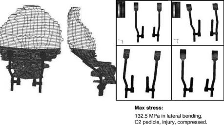
574 HUMAN SPINE, BIOMECHANICS OF
fusion. Some of these problems include observations of excessive motion (sometimes due to pseudoarthrosis) (155–164), degenerative changes (165,166), fracture dislocation (167), screw breakage or plate pullout (160,168– 170), and risks to neural structures. These problems are typically minimal when only one or two segments are involved in the injury. However, when the number of segments involved in the reconstruction increases to three or more, the incidence of failed fusion, screw breakage, and plate pullout increases dramatically.
Upper Cervical Spine Stabilization. Stabilization of the craniovertebral junction is not common; however, its importance for treating rheumatoid arthritis associated lesions, fractures and tumors cannot be underestimated. Currier et al. (171) studied the degree of stability provided by a rod-based instrumentation system. They compared this new device to the Ransford loop technique and a plate system using C2 pedicle screws. Transverse and alar ligament sectioning and odontoidectomy destabilized the specimen. All three-fixation systems significantly reduced motion as compared to intact and injured spines in axial rotation and extension. The new device did not significantly reduce motion at C1-C2 in flexion, and none of the devices were able to produce significant motion reductions in C1-C2 lateral bending. The authors claimed, based on these findings, that the new system is equivalent or superior to the other two systems for obtaining occipitocervical stability. Oda et al. (172) investigated the comparative stability afforded by five different fixation systems. Type II odontoid fractures were created to simulate instability. The results indicate that the imposed dens fracture decreased construct stiffness as compared to the intact case. Overall, the techniques that utilized screws for cervical anchors provided greater stiffness than the wiring techniques. Also, the system that utilized occipital screws with C2 pedicle screw fixation demonstrated the greatest construct stiffness for all rotations. Puttlitz et al. (1c) have used the finite element model of the C0-C1-C2 complex to investigate the biomechanics of a novel hardware system (Fig. 15). The FE models representing combinations of
cervical anchor type (C1-C2 transarticular screws versus C2 pedicle screws) and unilateral versus bilateral instrumentation were evaluated. All models were subjected to compression with pure moments in flexion, extension, or lateral bending. Bilateral instrumentation provided greater motion reductions than the unilateral hardware. When used bilaterally, C2 pedicle screws approximate the kinematic reductions and hardware stresses (except in lateral bending) that are seen with C1-C2 transarticular screws. The FE model predicted that the maximum stress was always located in the region where the plate transformed into the rod. Thus, the authors felt that C2 pedicle screws should be considered as an alternative to C2-Cl transarticular screw usage when bilateral instrumentation is applied.
Other strategies to fix the atlantoaxial complex can be found in the literature. Commonly available fixation techniques to stabilize the atlantoaxial complex are posterior wiring procedures (Brooks fusion, Gallie fusion) (169), interlaminar clamps (Halifax) (170), and transarticular screw (Magerl technique), either alone or in combination.
Posterior wiring procedures and interlaminar clamps are obviously easier to accomplish. However, these do not provide sufficient immobilization across the atlantoaxial complex. In particular, posterior wiring procedures and place the patient at risk of spinal cord injury due to sublaminar passage of wires into the spinal canal (172). Interlaminar clamps offer the advantage of avoiding the sublaminar wire hazard and have more rigid biomechanical stiffness than posterior wiring procedures (173).
Transarticular screw fixation (TSF), on the other hand, affords a stiffer atlantoaxial arthrodesis than posterior wiring procedures and interlaminar clamps. The TSF does have some drawbacks including injury of vertebral artery, malposition, and screw breakage (174). Furthermore, body habitus (obesity or thoracic hyperkyphosis) may prohibit achieving the low angle needed for screw placement across C1 and C2. Recently, a new technique of screw and rod fixation (SRF) that minimizes the risk of injury to the vertebral artery and allows intraoperative reduction has been reported (175,176). The configuration of this technique, which achieves rigid fixation of the atlantoaxial
Figure 15. The finite elment model showing the posterior fixation system and the stress plots in the rods. (Taken from Ref. 4c.)
complex, consists of lateral mass screws at C1 and pedicle screws at C2 linked via longitudinal rods with constrained coupling devices.
One recent study compared the biomechanical stability impaired to the atlantoaxial complex by either the TSF or SRF technique and to assess how well these methods withstand fatigue in a cadaver model (177).
The results of this study suggested that in the unilateral fixations, the SRF group was stiffer than the TSF group in flexion loading, but there were no evident differences in other directions. In the bilateral fixations, SRF was more stable than TSF, especially in flexion and extension. These results were similar to those reported by Melcher et al. (178) and Richter et al. (179), yet different from Lynch et al. (180). The instrumentation procedure (screw length, type of constrained coupling device, etc.), the destabilization technique, and the condition of the specimens might have an influence on the results. In this study, when stabilizing the atlantoaxial segments, all screws were placed bicortically in both techniques in accordance with procedures by Harms and Melcher (181). Previous work has demonstrated that bicortical cervical vertical screws are superior to unicortical screws in terms of pullout strength and decreased wobble (182,183). Most surgeons, however, prefer unicortical screwing at C1 and C2 levels to reduce the risk of penetration during surgery. This could affect the outcome. They initially connected the screw to the rod using the oval shape constrained coupling device recommended for use in C1 and C2 vertebras. However, the stability was not judged adequate, So they altered the procedure to use the stiffer circle shape constrained coupling device. With regards to the destabilization procedure, there are three typical methods: sectioning of intact ligaments, odontoid fracture, and odontoidectomy. The atlantoaxial complex was destabilized by ligament transection to simulate ligamentous instability, while Lynch et al. (180) used odontoidectomy. Furthermore, the bone quality of specimens affects the screw-bone interface stability. These factors were possibly reflected in other results. However, both results were not statistically different between TSF and SRF, so they could be interpreted equivalent in terms of effective stabilization when compared with the intact specimen.
In unilateral TSF and SRF, the fixed left lateral atlantoaxial joint acted as a pivot in left axial rotation and as a fulcrum in left lateral bending, thus leading to an increase in motion. This motion could be observed with the naked eye.
Stability in flexion and extension of the bilateral TSF group was inferior to that of SRF group. Henriques et al. (184) and Naderi et al. (182) also reported similar tendency. Henriques et al. (184) felt that this was most likely due to the transarticular screws being placed near the center of motion between C1 and C2. This was judged as another reason that the trajectory of the screws is consistent with the motion direction of flexion and extension. So, if TSF is combined with some posterior wiring procedures, the stability in flexion and extension will increase.
Lower Cervical Spine
Anterior Plating Techniques for Fusion. The anterior approach in order to achieve arthrodesis of the cervical
HUMAN SPINE, BIOMECHANICS OF |
575 |
spine has become a widely utilized and accepted approach. However, many of these techniques rely on insertion of a bone graft only anteriorly and the use of an external immobilization device, such as a halo vest, or posterior fixation in order to allow for sufficient fixation. Problems encountered with these methods include dislodging of the bone graft (potentially causing neural compromise), loss of angular correction, and failure to maintain spinal reduction (185,186). The use of anterior plates has recently become popular partially because they address some of the complications stated above. The main reasons typically cited for the use of anterior plates are (1) advantage of simultaneous neural decompression via an anterior as opposed to posterior approach, (2) improved fusion rates associated with anterior cervical fusion (187,188), (3) help in reduction of spinal deformities, (4) provides for rigid segmental fixation, and (5) prevents bone graft migration. However, the efficacy of anterior plates alone is still debated by some authors, particularly in multilevel reconstruction techniques, due to the high rates of failure observed, up to 50% in some cases (189–192). Thus, more biomechanical research must be accomplished to delineate the contributions of anterior plates to load sharing mechanics in the anterior approach.
There have been several in vitro studies examining the efficacy of anterior plates for use in a multitude of procedures involving cervical spine stabilization. Grubb et al. (151) performed a study involving 45 porcine and 12 cadaveric specimens to study anterior plate fixation. Phase I of the study involved intact porcine specimens which were subjected to nondestructive testing in flexion, lateral bending, and axial rotation loading modes to determine structural stiffness. Maximum moments applied included 2.7 N m for flexion and lateral bending and 3.0 N m for axial rotation testing. After completion of the nondestructive testing, a flexion-compression injury was introduced by performing a C5 corpectomy and inserting an iliac strut bone graft in the resulting space. An anterior plate was then introduced across C4–C6. Three different anterior plates were tested, including a Synthes CSLP (cervical spine locking plate) with unicortical fixation, a Caspar plate with unicortical fixation, and a Caspar plate with bicortical fixation. Each instrumented specimen was then tested again nondestructively in flexion, lateral bending, and axial rotation. Finally, destructive testing in each loading mode was performed on particular specimens in each plated group. Phase II of the study involved intact cadaver specimens that were subjected to nondestructive testing in flexion, lateral bending, and axial rotation loading modes to determine structural stiffness. Maximum moments applied included 2.0 N m for flexion, lateral bending, and axial rotation. After completion of the nondestructive testing, a flexion-compression injury was introduced by performing a C5 corpectomy and inserting an iliac strut bone graft in the resulting space. An anterior plate was then introduced across C4–C6. Two different anterior plates were tested: a Synthes CSLP (cervical spine locking plate) with unicortical fixation and a Caspar plate with bicortical fixation. Each instrumented specimen was then tested again nondestructively in flexion, lateral bending, and axial rotation. Finally, destructive testing in flexion
576 HUMAN SPINE, BIOMECHANICS OF
was performed on each specimen. Results of the study demonstrated that each of the stabilized specimens had stiffness characteristics greater than or equal to their paired intact test results. The CSLP was found to have a significantly higher stiffness ratio (plated: intact), higher failure moment, lower flexion neutral zone ratio, and higher energy to failure than the Caspar plates.
A study by Clausen et al. (193) reported the results of biomechanical testing of both the CSLP system with unicortical locking screws and Caspar plate system with unlocked bicortical screws. Fifteen cadaveric human spines were tested intact in flexion, extension, lateral bending, and axial rotation loading modes to determine stiffness characteristics. A C5-C6 instability was then introduced, consisting of a C5-C6 diskectomy with complete posterior longitudinal ligament (PLL) disruption. An iliac crest bone graft was then introduced into the C5-C6 disk space and the spine was instrumented with either the CSLP or Caspar system. Once instrumented, each of the spines were further destabilized through disruption of the interspinous and supraspinous ligaments, the ligamentum flavum, facet capsules, and lateral annulus. The specimens were then retested for stiffness. After initial postinstrumented testing was done, biomechanical stability of the specimens was reassessed following cyclic fatigue for 5000 cycles of flexion–extension. Finally, failure testing of each specimen was performed in flexion. Results of the study demonstrated that both devices stabilized the spine before but not after fatigue and that only the Caspar plate stabilized the spine significantly before and after fatigue. Failure moment did not differ between the two systems. Biomechanical stability discrepancy between the two devices was attributed to differences in bone–screw fixation. Kinematic testing of 10 cervical spines following single level (C5-C6) diskectomy and anterior plate insertion was studied by Schulte et al. (194). Results showed that the use of an anterior plate in addition to the bone graft provided significant stabilization in all loading modes. Traynelis et al. (195) performed biomechanical testing to compare anterior plating versus posterior wiring in an cadaver instability model involving a simulated C5 teardrop fracture with posterior disruption and fixation across C4-C6. Study results showed that bicortical anterior plating provided significantly more stability than posterior wiring in extension and lateral bending, and was slightly more stable than posterior wiring in flexion. Both provided equivalent stability in axial rotation. A variety of anterior constructs exist in the market today, typically using either bicortical screws or unicortical locking screws. Several studies have evaluated the purchase of unicortical versus bicortical screws in the cervical spine (195–197).
Wang et al. (198) looked at in vitro load transfer across standard tricortical grafts, reverse tricortical grafts, and fibula grafts, in the absence of additional stabilization. Using pressure sensitive film to record force levels on the graft, the authors found the greatest load on the graft occurred in 108 of flexion ( 20.5 N) with a preload on the spine of 44 N. As expected, the anterior portion of the graft bore increased loading in flexion and the posterior portion of the graft bore the highest loads in 108 extension. The authors did not supplement the anterior grafting with an
anterior plate. Cheng et al. (127) performed an in vitro study to determine load-sharing characteristics of two anterior cervical plate systems under axial compressive loads: the Aesculap system (Aesculap AGT, Tuttlingen, Germany) and the CerviLock system (SpineTech Inc., Minneapolis, MN). The percent loads carried by the plates at a 45 N applied axial load were as follows: Aesulap system6.2% 9.2% and the CerviLock system 23.8% 12.7%. Application of 90 N loads produced similar results to those of the 45 N loads. The authors stated that the primary factor in load transfer characteristics of the instrumented spine was a difference in plate designs. The study contained several limitations. Loading was performed solely in axial compression across a single FSU. The study did not simulate complex loading, such as flexion combined with compression. In the physiologic environment, load sharing in multisegmental cervical spine could be altered since the axial compressive load will produce additional flexion–extension moments, due to the lordosis. The upper and lower vertebras of the FSU tested were constrained in the load frame, whereas in reality they are free to move, subject to anatomic constraints. Foley et al. also performed in vitro experiments to examine the loading mechanics of multilevel strut grafts with anterior plate augmentation (199). The results of the study showed that application of an anterior plate in a cadaver corpectomy model unloads the graft in flexion and increases the loads borne by the graft under extension of the spine. The increase in load borne by the graft in the presence of the plate should increase the graft subsidence, a finding that is contrary to clinical follow-up studies, as stated earlier.
Finite element (FE) analysis has been used by our group on a C5-C6 motion segment model to determine load sharing in an intact spine under compressive loading and more clinically relevant combined loading of flexion–extension and compression (4b). Similarly, using the FE approach, stresses in various graft materials (titanium core, titanium cage, iliac crest, tantalum core, and tantalum cage), the adjacent disk space, and vertebra have been investigated by Kumareson et al. (200). These authors found that angular stiffness decreased with decreasing graft material stiffness in flexion, extension, and lateral bending. They also observed the stress levels in the disk and vertebral bodies as a whole due to the presence of a graft, but did not focus on the graft itself or the endplate regions, superior and inferior to the graft. The effects of anterior plates on load sharing were not investigated.
Scifert et al. (4d) developed an experimentally validated C4-C6 cervical spine finite element model was developed to examine stress levels and load sharing characteristics in an anterior plate and graft. Model predictions demonstrated good agreement with the in vitro data. The rotations across the stabilized segment significantly decreased in the presence of a plate as compared to graft alone case. Much like the in vitro studies, the model also predicted that the compressive load in the graft increased in extension in the presence of plate, as compared to graft alone case. Depending on the load type, stresses in graft were concentrated in its anterior or posterior region in the graft alone case and became more uniformly distributed in the presence of the plate. The predicted load-displacement data
and load sharing results reveal that plate is very effective in maintaining the alignment. Increase in load borne by the graft in the presence of a plate in the extension mode suggests that pistoning of the graft is a possible outcome. However, the stress data reported in the present study, and something that the in vitro studies are unable to quantify, show that pistoning of the graft is not likely to happen due to stresses being low, an observation in agreement with the clinical outcome data. For an optimal healing, the stress results suggest the placement of the tricortical bone graft with its cortical region towards the canal when a plate is used. For the graft case alone, this parameter does not seem to be that critical. A more uniform stress distribution in the graft in the presence of the plate would tend to promote bone fusion in a more uniform fashion, as compared to the graft alone case. In the later case fusion may initiate in a selective region.
Lower Cervical Spine
Posterior Plating Techniques for Fusion. The posterior approach in order to achieve cervical spine arthrodesis has been a widely utilized and accepted approach to dealing with cervical spine trauma, such as posterior trauma involving the spinous processes or facet dislocation or injury, and disease, such as degenerative spondylosis or ossification of the posterior longitudinal ligament. Recently, however, posterior fixation using cervical screw plates affixed to the lateral masses has gained acceptance due to a variety of factors, including the fact that they do not rely on the integrity of the lamina or spinous processes to allow for fixation, bone grafting is not always necessary to allow for long-term stability, greater rotational stability is achieved at the facets (201,202), and it eliminates the need for external immobilization such as halo vests. Problems encountered with these posterior methods include (1) risk to nerve roots, vertebral arteries, facets, and spinal cord (168); (2) screw loosening and avulsion (203); (3) plate breakage; (4) and loss of reduction. Additionally, contraindications exist where the patient has osteoporosis, metabolic bone disease, or conditions where the bone is soft (i.e., ankylosing spondylitis) (204). There also exists controversy as to the advantages of using posterior plating techniques when posterior cervical wiring techniques can be used (205). In theory, anterior stabilization of the spine in cases of vertebral body injury is superior to posterior plating. However, in practice, posterior plates are an effective means of stabilizing vertebral body injuries, and their application is easier than the anterior approach involving corpectomy, grafting, and anterior plating.
In addition to clinical in vivo studies, there have been several in vitro studies examining the efficacy of posterior plates for use in cervical spine stabilization. Roy-Camille et al. (202) utilized a cadaveric model to compare posterior lateral mass plating to spinous process wiring. They found that posterior plates increased stability by 92% in flexion and 60% in extension, while spinous process wiring enhanced flexion stability by only 33% and did not stabilize in extension at all Coe et al. (201) performed biomechanical testing of several fixation devices, including Roy-Camille posterior plates, on six human cadaveric spines. Complete
HUMAN SPINE, BIOMECHANICS OF |
577 |
disruption of the supraspinous and interspinous ligaments, ligamentum flavum, posterior longitudinal ligament, and facet joints was performed. They found no significant difference in static or cyclic loading results between the posterior wiring and posterior plates, although the posterior plating was stiffer in torsion. Overall, the authors recommended the Bohlmann triple wire technique for most flexion distraction injuries. In experimental studies performed in our lab on 12 cervical spines, Scifert et al. (202) found that posterior plates were superior to posterior facet wiring in almost every loading mode tested in both the stabilized and cyclic fatigue testing modes, excluding the cyclic extension case. Smith et al. (153) performed biomechanical tests on 22 spines to evaluate the efficacy of Roy-Camille plates in stabilization of the cervical spine following simulation of a severe fracture dislocation with three-column involvement caused by forced flexion-rotation of the head. Results of the study indicated that the posterior plating system decreased motion significantly compared to the intact spine, specifically by a factor of 17 in flexion–extension and a factor of 5 units in torsion. Raftopoulos et al. (203) found that both posterior wiring and posterior plating resulted in significant stability following severe spinal destabilization, although posterior plating provided superior stability compared to that of interfacet wiring. Similar to the results of anterior plates, Gill et al. (204) found that bicortical lateral posterior plate screw fixation provided greater stability than unicortical fixation. However, Grubb et al. (151) found that unicortical fixation of a destabilized spine using a cervical rod device provided equivalent stability in torsion and lateral bending as bicortical fixation using an AO lateral mass plate. Effectiveness of 3608 plating techniques for fusion.
As stated previously, both anterior and posterior plating procedures contain inherent difficulties and drawbacks. Some authors have examined the utilization of both techniques concomitantly to ensure adequate stabilization. Lim et al. (205) examined both anterior only, posterior only, and combined techniques in vitro to determine efficacy of these techniques in stabilizing either a C4-C5 flexion-distraction injury or an injury simulating a C5 burst fracture involving a C5 corpectomy. The AXIS and Orion plates were used for posterior and anterior stabilization, respectively. In the C4-C5 flexion-distraction injury, both posterior and combined fixation reduced motion significantly from intact in flexion. Only the combined procedure was able to reduce motion effectively in extension. In lateral bending and axial rotation, posterior fixation alone and combined fixation were able to significantly reduce motion compared to intact. In the C5 corpectomy model, all constructs exhibited significantly less motion compared to intact in flexion, although the combined fixation was the most rigid. In extension, all constructs except the posterior fixation with bone graft were able to reduce motion significantly compared to intact. In lateral bending, only the posterior fixation and combined fixation were able to provide enhanced stability compared to intact. In axial rotation, only the combined fixation was able to significantly reduce motion compared to intact. Thus, the authors concluded that combined fixation provided the most rigid
578 HUMAN SPINE, BIOMECHANICS OF
stability for both surgical cases tested. In a clinical study of multilevel anterior cervical reconstruction surgical techniques, Doh et al. (190) found a 0% psuedoarthrosis rate for the combined fixation system only.
Although combined fixation almost certainly allows for the most rigid fixation in most unstable cervical spine injuries, there are other factors to consider, such as the necessity for an additional surgery, possibility of severely reduced range of motion, and neck pain, Jonsson et al. (206) found a propensity for 22 out of 26 patients with combined fixation to have pain related to the posterior surgery. Additionally, patients with the combined fixation were found to have considerably restricted motion compared to normal. These and other factors must be weighed with the additional advantages of almost assured stability with the combined fixations.
Interbody Fusion Cage Stabilization for Fusion
Interbody fusion in the cervical spine has traditionally been accomplished via the anterior and posterior methods, incorporating the use of anterior or posterior plates, usually with the concomitant use of bone grafts. However, recently, interbody fusion cages using titanium mesh cages packed with morselized bone have been reported for use in the cervical spine. Majid et al. (163) performed channeled corpectomy on 34 patients, followed by insertion of a titanium cage implant packed with autogenous bone graft obtained from the vertebral bodies removed in the corpectomy. The authors then performed additional anterior plating on 30 of the 34 patients that involved decompression of two or more levels. Results of the study indicated a 97% radiographic arthrodesis rate in the patient population, with a 12% complication rate including pseudoarthrosis, extruded cage, cage in kyphosis, and radiculopathy. The authors concluded that titanium cages provide immediate anterior column stability and offer a safe alternative to autogenous bone grafts.
Two recent studies examined the biomechanics of anterior cervical interbody cages. Hacker et al. (207) conducted a randomized multicenter clinical trial looking at three different study cohorts of anterior cervical diskectomy fusions: instrumented with HA-coated BAK-C, instrumented with noncoated BAK-C, and uninstrumented, bone graft only (ACDF) fusions. There were a total of 488 patients in the trial, with 288 included in the 1 year follow up and 140 in the 2 year follow up. There were 79.9% onelevel fusions and 20.1% two-level fusions performed. Results showed no significant differences between the coated or noncoated BAK-C devices, leading the authors to combine these groups for analysis. Complication rate with the BAK-C group of 346 patients was 10.1% and the ACDF group of 142 patients demonstrated an overall complication rate of 16.2%. The fusion rates for the BAK-C and ACDF fusions at 12 months for one level were 98.7 and 86.4%, respectively; for two levels, 80.0 and 80.0%, respectively. The fusion rates for the BAK-C and ACDF fusions at 24 months for one level were 100 and 96.4%, respectively; for two levels, 91.7 and 77.8%, respectively. Overall, the authors found that the BAK-C cage performed comparably to conventional, uninstrumented, bone graft
only anterior diskectomy and fusion. In an in vitro comparative study, Yang et al. (208) compared the initial stability and pullout strength of five different cervical cages and analyzed the effect of implant size, placement accuracy, and tightness of the implant on segmental stability. The cages analyzed included (1) SynCage-C Curved, (2) SynCage-C Wedged, (3) Brantigan I/F, (4) BAK-C, and (5) ACF Spacer. Overall, 35 cervical spines were used, with a total number of 59 segments selected for the study. Flexibility testing was performed under 50 N preload and up to 2 N m in flexion, extension, lateral bending, and axial rotation. After quasistatic load tests were completed, the cages were subjected to an anterior pull-out test. Direct measurement on the specimen and biplanar radiographs allowed for quantification of distractive height, change in segmental lordosis, cage protrusion, and cage dimensions normalized to the endplate. Results from the study indicated that, in general, the cages were effective in reducing ROM in all directions by approximately one-third, but failed to reduce the neutral zone (NZ) in flexion/extension and axial rotation. Additionally, differences in implants were not significant and only existed between the threaded and nonthreaded designs. The threaded BAK-C was found to have the highest pullout force. Pullout force and lordotic change were both identified as significant predictors of segmental stability, a result the authors underscored as emphasizing the importance of a tight implant fit within the disk space.
RHAKOSS C synthetic bone spinal implant (Orthovita Inc., Malvern, PA) is trapezoidal in shape with an opening in the center for bone graft augmentation, and is fabricated from a bioactive glass/ceramic composite. In vitro testing conducted by Goel et al. (209) was conducted to evaluate the expulsion and stabilizing capabilities of the cervical cage in the lower cervical spine; C6/7 and C4/5 motion segments. from five of the spinal donors were used for the expulsion testing. All specimens received the ‘‘Narrow Lordotic’’ version of the Rhakoss C design. The cages were implanted by orthopedic surgeons following manufacturer recommendations. Specimens were tested in various modes; intact, destabilized with the cage in place, cage plus an anterior plate (Aline system, Surgical Dynamics Inc., Norwalk, CT), and again with the cage and plate after fatigue loading of 5000 flexion–extension cycles of 1.5 N m. The results of the expulsion testing indicate that BMD and patient age are good predictors of implant migration resistance (r ¼ 0.8). However, the high BMD/age correlation in the specimens makes it difficult to distinguish the relative importance of these two factors. The stability testing demonstrated the ability of a cage with a plate construct to sufficiently stabilize the cervical spine. However, BMD and specimen age play a major role in determining the overall performance of the cervical interbody cage.
Totribe (210) undertook a biomechanical comparison of a new cage made of a forged composite of unsinteredhydroxyapatite particles–poly-L-lactide (F-u-HA-PLLA) and the Ray threaded fusion cage. The objectiove was to compare the stability imparted to the human cadaveric spine by two different threaded cervical cages, and the effect of cyclic loading on construct stability. Threaded cages have been developed for use in anterior cervical
interbody fusions to provide initial stability during the fusion process. However, metallic instrumentation has several limitations. Recently, totally bioresorbable bone fixation devices made of F-u-HA/PLLA have been developed, including a cage for spinal interbody fusion. Twelve fresh ligamentous human cervical spines (C4-C7) were used. Following anterior diskectomy across C5-C6 level, stabilization was achieved with the F-u-HA/PLLA cage in six spines and the Ray threaded fusion cage in the remaining six. Biomechanical testing of the spines was performed with six degrees of freedom before and after stabilization, and after cyclic loading of the stabilized spines (5000 cycles of flexion–extension at 0.5 N m). The stabilized specimens (with F-u-HA/PLLA cage or the Ray cage) were significantly more stable than the diskectomy case in all directions except in extension. In extension, both groups were stiffer, although not at a significant level (P >0.05). Following fatigue, the stiffness, as compared to the prefatigue case, decreased in both groups, although not at a significant level. The Ray cage group exhibited better stability than the F-u-HA/PLLA cage group in all directions, although a significant difference was found only in right axial rotation.
Lumbar Spine
Anterior and Posterior Spinal Instrumentation. The stability analysis of devices with varying stiffness is best exemplified by a study of Gwon et al. (211) who tested three different transpedicular screw devices: spinal rod-transpe- dicular screw system (RTS), the Steffee System (VSP), and Crock device (CRK). All devices provided statistically significant (P < 0.01) motion reductions across the affected level (L4-L5). The differences among the three devices in reducing motion across L4-L5, however, were not significant. Also, the changes in motion patterns of segments adjacent to the stabilized level compared with the intact case were not statistically significant. These findings have been confirmed by Rohlmann and associates who used a finite element model to address several implant related issues, including this one (212).
In an in vitro study, Weinhoffer et al. (213) measured intradiskal pressure in lumbosacral cadaver specimens subjected to constant displacement before and after applying bilateral pedicle screw instrumentation across L4-S1. They noted that intradiskal pressure increased in the disk above the instrumented levels. Also, the adjacent level effect was confounded in two-level instrumentation compared with single-level instrumentation. Other investigators, in principle, have reported similar results. Completely opposite results, however, are presented by several others (212). Results based on in vitro studies must be interpreted with caution, being dependent on the testing mode chosen (displacement or load control) for experiments. In the displacement control-type studies, in which applied displacement is kept constant during testing of intact and stabilized specimens, higher displacements and related parameters (e.g., intradiskal pressure) at the adjacent segments are reported. This is not true for the results based on the load control-type studies, in which the applied loads are kept constant.
HUMAN SPINE, BIOMECHANICS OF |
579 |
Lim et al., assessed the biomechanical advantages of diagonal transfixation compared to horizontal transfixation (214). Diagonal cross-members yielded more rigid fixation in flexion and extension, but less in lateral bending and axial rotational modes, as compared to horizontal cross-members. Furthermore, greater stresses in the pedicle screws were predicted for the system having diagonal cross members. The use of diagonal configuration of the transverse members in the posterior fixation systems did not offer any specific advantages, contrary to the common belief.
Biomechanical cadaver studies of anterior fusion promoting and stabilizing devices (214–217) have become increasingly more common in the literature, owing to this procedure’s rising popularity (105). In vitro testing was performed using the T9-L3 segments of human cadaver spines (218). An L-1 corpectomy was performed, and stabilization was achieved using one of three anterior devices: the ATLP in nine spines, the SRK in 10, and the Z-plate in 10. Specimens were load tested. Testing was performed in the intact state, in spines stabilized with one of the three aforementioned devices after the devices had been fatigued to 5000 cycles at 3 N m, and after bilateral facetectomy. There were no differences between the SRKand Z-plate- instrumented spines in any state. In extension testing, the mean angular rotation ( standard deviation) of spines instrumented with the SRK (4.7 3.28) and Z-plate devices (3.3 2.38) was more rigid than that observed in the ATLPstabilized spines (9 4.88). In flexion testing after induction of fatigue, however, only the SRK (4.2 3.28) was stiffer than the ATLP (8.9 4.98). Also, in extension postfatigue, only the SRK (2.4 3.48) provided more rigid fixation than the ATLP (6.4 2.98). All three devices were equally unstable after bilateral facetectomy. The SRK and Z-plate anterior thoracolumbar implants were both more rigid than the ATLP, and of the former two the SRK was stiffer. The results suggest that in cases in which profile and ease of application are not of paramount importance, the SRK has an advantage over the other two tested implants in achieving rigid fixation immediately postoperatively.
Vahldiek and Panjabi investigated the biomechanical characteristics of short-segment anterior, posterior, and combined instrumentations in lumbar spine tumor vertebral body replacement surgery (219). The L2 vertebral body was resected and replaced by a carbon-fiber cage. Different fixation methods were applied across the L1 and L3 vertebrae. One anterior, two posterior, and two combined instrumentations were tested. The anterior instrumentation, after vertebral body replacement, showed greater motion than the intact spine, especially in axial torsion (range of motion, 10.3 vs. 5.58; neutral zone, 2.9 vs. 0.78; P <0.05). Posterior instrumentation provided greater rigidity than the anterior instrumentation, especially in flexion–extension (range of motion, 2.1 vs. 12.68; neutral zone, 0.6 vs. 6.18; P < 0.05). The combined instrumentation provided superior rigidity in all directions compared with all other instrumentations. Posterior and combined instrumentations provided greater rigidity than anterior instrumentation. Anterior instrumentation should not be used alone in vertebral body replacement.
580 HUMAN SPINE, BIOMECHANICS OF
Oda et al. nondestructively compared three types of anterior thoracolumbar multisegmental fixation with the objective to investigate the effects of rod diameter and rod number on construct stiffness and rod–screw strain (220). Three types of anterior fixation were then performed at L1L4: (1) 4.75 mm diameter single rod, (2) 4.75 mm dual-rod, and (3) 6.35 mm single-rod systems. A carbon fiber cage was used for restoring intervertebral disk space. Single screws at each vertebra were used for single-rod and two screws for dual-rod fixation. The 6.35 mm single-rod fixation significantly improved construct stiffness compared with the 4.75 mm single rod fixation only under torsion (P <0.05). The 4.75 mm dual rod construct resulted in significantly higher stiffness than did both single-rod fixations (P <0.05), except under compression. For single-rod fixation, increased rod diameter neither markedly improved construct stiffness nor affected rod–screw strain, indicating the limitations of a single-rod system. In thoracolumbar anterior multisegmental instrumentation, the dual-rod fixation provided higher construct stiffness and less rod–screw strain compared with single-rod fixation.
Lumbar Interbody Cages. Cage related biomechanical studies range from evaluations of cages as stand alone devices to use of anterior or posterior instrumentation for additional stabilization.The changes in stiffness and disk height of porcine FSUs by installation of a threaded interbody fusion cage and those by gradual resection of the annulus fibrosus were quantified (117). Flexion, extension, bending, and torsion testing of the FSUs were performed in four sequential stages: stage I, intact FSU; stage II, the FSUs were fitted with a threaded fusion cage; stage III, the FSUs were fitted with a threaded fusion cage with the anterior one-third of the annulus fibrosus excised, including excision of the anterior longitudinal ligament; and stage IV, in addition to stage III, the bilateral annulus fibrosus was excised. Segmental stiffness in each loading in the four stages and a change of disk height induced by the instrumentation were measured. After instrumentation, stiffness in all loading modes (p <0.005) and disk height (p ¼ 0.002) increased significantly. The stiffness of FSUs fixed by the cage decreased with gradual excision of the annulus fibrosus in flexion, extension, and bending. These results suggest that distraction of the annulus fibrosus and posterior ligamentous structures by installation of the cage increases the soft-tissue tension, resulting in compression to the cage and a stiffer motion segment. This study explains the basic mechanism through which the cages may provide the stability in various loading modes.
Three posterior lumbar interbody fusion implant constructs (Ray Threaded Fusion Cage, Contact Fusion Cage, and PLIF Allograft Spacer) were tested for stability in a cadaver model (221). None of the standalone implant constructs reduced the neutral zone (amount of motion in response to minimal load application). The constructs decreased the range of motion in flexion and lateral bending. The data did not suggest any implant construct to behave superiorly. Specifically, the PLIF Allograft Spacer is biomechanically equivalent to titanium cages and is devoid of the deficiencies associated with metal cages. Therefore, the PLIF Allograft Spacer is a valid alternative to conventional cages.
The lateral, and other cage orientations within the disk have been increasingly used for fusion (222). In one study, 14 spines were randomized into the anterior group (anterior diskectomy and dual anterior cage—TFC placement) and the lateral group (lateral diskectomy and single transverse cage placement) for load-displacement evaluations. Segmental ranges of motion were similar between spines undergoing either anterior or lateral cage implantation. Combined with a decreased risk of adjacent structure injury through a lateral approach, these data support a lateral approach for lumbar interbody fusion. When used alone to restore stability, the orientation of the cage (oblique vs. posterior) effected the outcome (223). Likewise, in flexion, both the OBAK (Oblique placement of one cage) and CBAK (Conventional posterior placement of two cages) orientations provided significant stability. In lateral bending, CBAK orientation was found to be better then OBAK. In axial mode, CBAK orientation was significantly effective in both directions while OBAK was effective only in right axial rotation. Owing to the differences in the surgical approach and the amount of dissection, the stability for the cages when used alone as a function of cage orientation was different.
The high elastic modulus of the cages causes the structures to be very stiff and may lead to stress-shielded environments within the devices with potential adverse effect on growth of the cancellous bone within the cage itself (224). Using a calf spine model, a study was designed to compare the construct stiffness afforded by 11 differently designed anterior lumbar interbody fusion devices: four different threaded fusion cages: (BAK device, BAK Proximity, Ray TFC, and Danek TIBFD); five different nonthreaded fusion devices (oval and circular Harms cages, Brantigan PLIF and ALIF cages, and InFix device); two different types of allograft (femoral ring and bone dowel); and to quantify their stress-shielding effects by measuring pressure within the devices. Prior to testing, a silicon elastomer was injected into the cages and intra cage pressures were measured using pressure needle transducers. No statistical differences were observed in construct stiffness among the threaded cages and nonthreaded devices in most of the testing modalities. Threaded fusion cages demonstrated significantly lower intracage pressures compared with nonthreaded cages and structural allografts. Compared with nonthreaded cages and structural allografts, threaded fusion cages afforded equivalent reconstruction stiffness but provided more stress-shielded environment within the devices. (This stress shielding effect may further increase in the presence of supplementary fixation devices.)
It is known that micromotion at the cage–endplate interface can influence bone growth into its pores. Loading conditions, mechanical properties of the materials, friction coefficients at the interfaces, and geometry of spinal segments would affect relative micromotion and spinal stability. In particular, relative micromotion is related closely to friction at bone–implant interfaces after arthroplasty. A high rate of pseudarthrosis and a high overall rate of implant migration requiring surgical revision has been reported following posterior lumbar interbody fusion using BAK threaded cages (225). This may be due to poor fixation
of the implant, in addition to the stress shielding phenomena described above. Thus, Kim developed an experimentally validated finite element model of an intact FSU and the FSU implanted with two threaded cages to analyze the motion of threaded cages in posterior lumbar interbody fusion (226). Motion of the implants was not seen in compression. In torsion, a rolling motion was noted, with a range of motion of 10.68 around the central axis of the implant when left–right torsion (25 N m) was applied. The way the implants move within the segment may be due to their special shape: the thread of the implants cannot prevent the BAK cages rolling within the disk space. However, note that the authors considered too high a value of torsional load; such values may not be clinically relevant. Relative micromotion (slip distance) at the interfaces was obvious at their edges under axial compression. The slip occurred primarily at the anterior edges under torsion with preload, whereas it occurred primarily at the edges of the left cage under lateral bending with preload. Relative micromotion at the interfaces increased significantly as the apparent density of cancellous bone or the friction coefficient of the interfaces decreased. A significant increase in slip distance at the anterior annulus occurred with an addition of torsion to the compressive preload. Relative micromotion was sensitive to the friction coefficient of the interfaces, the bone density, and the loading conditions. A reduction in age-related bone density was less likely to allow bone growth into surface pores of the cage. It was likely that the larger the disk area the more stable the interbody fusion of the spinal segments. However, the amount of micromotion may change in the presence of a posterior fixation technique, an issue that was not reported by the authors.
Almost every biomechanical study has shown that interbody cages alone, irrespective of their shapes, sizes, surface type, material, and approach used for implantation, does not stabilize the spine in all of the modes. It is suspected that this may be caused by the destruction of the appropriate spinal elements like the anterior longitudinal ligament, and anterior annulus fibrosus, or facets. Thus, use of additional instrumentation to augment cages seems to have become a standard procedure.
The 3D flexibility in ligamentous human lumbar spinal units have been investigated after the anterior, anterolateral, posterior, or oblique insertion of various types of interbody cages with supplemental fixtion using anterior or posterior spinal instrumentation (227). With the supplementary fixation using transfacet screws, the differences in stability due to the orientations were not noticeable at all, both before and after; underscoring the importance of using instrumentation when cages are used.
Patwardhan et al. (228) tested the hypothesis that the ability of the ALIF cages to reduce the segmental motions in flexion and extension will be significantly affected by the magnitude of the compressive preload. Fourteen human lumbar spine specimens (L1-sacrum) were tested intact, and after insertion of two threaded cylindrical cages at L5S1. They were tested in flexion–extension with progressively increasing magnitude of compressive preload from 0 to 1200 N applied along the follower load path (described earlier). The stability of the stand-alone cage construct was
HUMAN SPINE, BIOMECHANICS OF |
581 |
significantly affected by the amount of compressive preload applied across the operated segment. In contrast to the extension instability reported in the literature, the twocage construct exerted a stabilizing effect on the motion segment (reduction in segmental motion) in extension under physiologic compressive preloads. The cages provided substantially more stability, both in flexion and in extension, at larger preloads (800–1200 N) corresponding to standing and walking activities as compared to the smaller preloads (200–400 N) experienced during supine and recumbent postures. The compressive preload due to muscle activity likely plays a substantial role in stabilizing the segment with interbody cages.
The function of the interbody fusion cages is to stabilize the spinal segment primarily by distracting them as well as allowing bone ingrowth and fusion (122). An important condition for efficient formation of bone tissue is achieving adequate spinal stability. However, the initial stability may be reduced due to repeated movements of the spine during activities of daily living. Before and directly after implanation of a Zientek, Stryker, or Ray posterior lumbar interbody fusion cage, 24 lumbar spine segments were evaluated for stability analyses. The specimens were then loaded cyclically for 40,000 cycles at 5 Hz with an axial compression load ranging from 200 to 1000 N. The specimens were tested again in the spine tester. Generally, a decrease in motion in all loading modes was noted after insertion of the Zietek and Ray cages and an increase after implantation of a Stryker cage. In all three groups, greater stability was demonstrated in lateral bending and flexion then in extension and axial rotation. Reduced stability during cyclic loading was observed in all three groups; however, loss of stability was most pronounced in Ray cage group. Authors felt that this may be due to the damage of the cage: bone interface during cyclic loading that was not the case for the other two since they have a flat brick type interface. In order to reduce the incidence of stress risers at the bone–implant interface, it is essential that interbody fusion implants take advantage of the cortical periphery of the vertebral endplates. A larger cross-sectional footprint to the implant design will aid in dispersing the axial forces of spinal motion over a larger surface area and minimize the risk of stress risers, which may result in endplate fractures.
Animal Models
An approximation of the in vivo performance of spinal implants in humans can be attained by evaluation in animal models (229). Specifically, animal models provide a dynamic biologic and mechanical environment in which the implant can be evaluated. Temporal changes in both the host biologic tissue and instrumentation can be assessed with selective incremental sacrificing of the animals. Common limitations of animal studies include the method of loading (quadruped versus biped) and the size adjustment of devices needed such that proper fit is achieved in the animals.
Animal studies have revealed the fixation benefits of grouting materials in the preparation of the screw hole (230). The major findings were that the HA grouting of
582 HUMAN SPINE, BIOMECHANICS OF
the screw hole bed before insertion significantly increased fixation (pullout) of the screws. Scanning electron microscopy analysis revealed that HA plasma spraying had deleterious effects on the screw geometry, dulling the self-tapping portion of the screw and reducing available space for bony in-growth.
An animal model of anterior and posterior column instability was developed by McAfee et al. (231–233) to allow in vivo observation of bone remodeling and arthrodesis after spinal instrumentation. An initial anterior and posterior destabilizing lesion was created at the L5–6 vertebral levels in 63 adult Beagle dogs. Observations 6 months after surgery revealed a significantly improved probability of achieving a spinal fusion if spinal instrumentation had been used. Nondestructive mechanical testing after removal of all metal instrumentation in torsion, axial compression, and flexion revealed that the fusions performed in conjunction with spinal instrumentation were more rigid. Quantitative histomorphometry showed that the volumetric density of bone was significantly lower (i.e., device-related osteoporosis occurred) for fused versus unfused spines. In addition, a linear correlation occurred between decreasing volumetric density of bone and increasing rigidity of the spinal implant; device-related osteoporosis occurred secondary to Harrington, Cotrel-Dubousset, and Steffee pedicular instrumentation. However, the stressinduced changes in the bone quality found in the animal models is not likely to correlate well with the actual changes in the spinal segment of a patient. In fact, it is suggested that the degeneration in a patient may be determined more by individual characteristics than by the fusion itself (234).
In long bone fractures, internal fixation improves the union rate, but does not accelerate the healing process. Spinal instrumentation also improves the fusion rate in spinal arthrodesis. However, it remains unclear whether the use of spinal instrumentation expedites the healing process of spinal fusion (235,236). Accordingly, an in vivo sheep model was used to investigate the effect of spinal instrumentation on the healing process of posterolateral spinal fusion. Sixteen sheep underwent posterolateral spinal arthrodeses at L2-L3 and L4-L5 using equal amounts of autologous bone. One of those segments was selected randomly for further augmentation with transpedicular screw fixation (Texas Scottish Rite Hospital spinal system). The animals were killed at 8 or 16 weeks after surgery. Fusion status was evaluated through biomechanical testing, manual palpation, plain radiography, computed tomography, and histology. Instrumented fusion segments demonstrated significantly higher stiffness than did uninstrumented fusions at 8 weeks after surgery. Radiographic assessment and manual palpation showed that the use of spinal instrumentation improved the fusion rate at 8 weeks (47 vs. 38% in radiographs, 86 vs. 57% in manual palpation). Histologically, the instrumented fusions consisted of more woven bone than the uninstrumented fusions at 8 weeks after surgery. The 16-week-old fusion mass was diagnosed biomechanically, radiographically, and histologically as solid, regardless of pedicle screw augmentation. The results demonstrated that spinal instrumentation created a stable mechanical environment to enhance the early bone healing of spinal fusion.
Human Clinical Models
Loads in posterior implants were measured in 10 patients using telemeterized internal spinal fixation devices (237– 239). Implant loads were determined in up to 20 measuring sessions for different activities, including walking, standing, sitting, lying in the supine position, and lifting an extended leg while in the supine position. Implant loads often increased shortly after anterior interbody fusion was performed. Several patients retained the same high level even after fusion had taken place. This explains the reason why screw breakage sometimes occurs more than half a year after implantation. The time of fusion could not be pinpointed from the loading curves. A flexion bending moment acted on the implant even when the body was in a relaxed lying position. This meant that already shortly after the anterior procedure, the shape of the spine was not neutral and unloaded, but slightly deformed, which loaded the fixators. In another study, the same authors used the telemeterized internal spinal fixation devices to study the influence of muscle forces on the implant loads in three patients before and after anterior interbody fusion. Contracting abdominal or back muscles in a lying position was found to significantly increase implant loads. Hanging by the hands from wall bars as well as balancing with the hands on parallel bars reduced the implant loads compared with standing; however, hanging by the feet with the head upside down did not reduce implant loads, compared with lying in a supine position. When lying on an operating table with only the foot end lowered so that the hips were bent, the patient had different load measurements in the conscious and anesthetized states before anterior interbody fusion. The anesthetized patient evidenced predominately extension moments in both fixators, whereas flexion moments were observed in the right fixator of the conscious patient. After anterior interbody fusion had occurred, the differences in implant loads resulting from anesthesia were small. The muscles greatly influence implant loads. They prevent an axial tensile load on the spine when part of the body weight is pulling, for example, when the patient is hanging by their hands or feet. The implant loads may be strongly altered when the patient is under anesthesia.
The above review clearly shows that a large number of fusion enhancement instrumentation are available to surgeons. However, none of the instrumentation is totally satisfactory in its performance and there is room to improve the rate of fusion success, if fusion is the goal. Naturally, alternative fusion approaches (mechanical, biological) are currently being pursued.
The rigidity of a spinal fixation device and its ability to share load with the fusion mass are considered essential for the fusion to occur. If the load transferred through the fusion mass, is increased without sacrificing the rigidity of the construct, a more favorable environment for fusion may be created. To achieve this objective, posterior as well as anterior ‘‘dynamized’’ systems have been designed (240–242). One such posterior system consists of rods and pedicle screws and has a hinged connection between the screw head and shaft compared with the rigid screws (Fig. 16a). Another example of the dynamized anterior system (ALC) is shown in Fig. 16b. Load-displacement
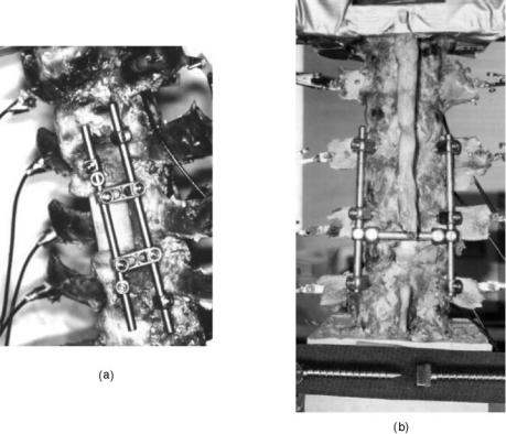
HUMAN SPINE, BIOMECHANICS OF |
583 |
tests were performed to assess the efficacy of these devices in stabilizing a severally destabilized spinal segment. The hinged and rigid posterior systems provided significant stability across the L2-L4 segment in flexion, extension, and lateral bending as compared with the intact case (P <0.5). The stabilities imparted by the hinged-type and its alternative rigid devices were of similar magnitudes. The ALC dynamized and rigid anterior systems also provided significant stability across the L3-L5 segment in flexion, extension, and lateral bending (P <05). The stability imparted by the Dynamized ALC and its alternate rigid system did not differ significantly.
Dynamic stabilization may provide an alternative to fusion for patients suffering from early degenerative disk disease (DDD). The advantages of using a dynamic system are, preservation of the disk loading, allowing some physiologic load sharing in the motion segment. A finite element (FE) study was done to understand the effect of a commercially available dynamic system (DYNESYS, Zimmer Spine) compared to a rigid system on the ROM and disk stresses at the instrumented level (243). An experimentally validated 3-D FE model of intact L3-S1 spine was modified to simulate rigid and dynamic systems across L4-L5 level with the disk intact. The DYNESYS spacer and ligament were modeled with truss elements, with the ‘‘no tension’’ and ‘‘no compression’’ options, respectively. The ROM and disk stresses in response to a 400 N axial compression and 10.6-N m flexion–extension moment were calculated. The ROM and disk stresses of the adjacent levels with rigid and DYNESYS systems had no significant change when compared to the intact. At the instrumented level in flexion–extension the decrease in motion when
Figure 16. The two different types of dynamized systems used in a cadaver model to assess their stability characteristics. The data were compared with the corresponding ‘‘rigid’’ systems. (a) Posterior system and (b) anterior system. (Taken from Refs. 242 and 241.)
compared to the intact was 68/84% for rigid system and 50/56% for DYNESYS. The peak Von Mises disk stresses at the instrumented segment reduced by 41/80% for the rigid system, 27/45% for the DYNESYS system for flexion– extension loading condition. The predicted motion data for the dynamic system was in agreement with the experimental data. From the FE study it can be seen that the DYNESYS system allows more motion than the rigid screw-rod system, and hence allows for partial disk loading. This partial disk loading might be advantageous for a potential recovery of the degenerated disk, thus making dynamic stabilization systems a viable option for patients in early stages of DDD.
An anterior bone graft in combination with posterior instrumentation has been shown to provide superior support because the graft is in line with axial loads and the posterior elements are left intact. However, employing posterior instrumentation with anterior grafting requires execution of two surgical procedures. Furthermore, use of a posterior approach to place an interbody graft requires considerable compromise of the posterior elements, although it reduces the surgery time. It would be advantageous to minimize surgical labor and structural damage caused by graft insertion into the disk space via a posterior approach. Authors have addressed this issue by preparing an interbody bone graft using morselized bone (244–246). This device is a gauze bag of Dacron that is inserted into the disk space, filled with morselized bone, and tied shut, Fig. 17. In vitro testing measured the rotations of each vertebral level of mechanically loaded cadaver lumbar spines, both in intact and several experimental conditions. With the tension band alone, motion was restored to the
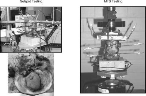
584 HUMAN SPINE, BIOMECHANICS OF
Figure 17. The Bag system developed by Spineology Inc. The increases and decreases in motion with respect to intact segment for bag alone and bag with a band are also shown. (Taken from Ref. 244.)
intact case, except in extension where it was reduced. With the graft implant, motion was restored to intact in all of the loading modes, except in flexion where it was reduced. With the tension band and graft, motion was again restored to intact except in flexion and extension where it was reduced. In vitro results suggest that a tension band increases stability in extension, while the bag device alone seems to provide increased stability in flexion. The implanted bag filled with morselized bone in combination with a posterior tension band, restores intact stiffness. Postcyclic results in axial compression suggest that the morselized bone in the bone-only specimens either consolidates or extrudes from the cavity despite confinement. Motion restoration or reduction as tested here is relevant both to graft incorporation and segment biomechanics. The posterior interbody grafting method using morselized bone is amenable to orthoscopy. It produces an interbody graft without an anterior surgical approach. In addition, this technique greatly reduces surgical exposure with minimal blood loss and no facet compromise. This technique would be a viable alternative to current 3608 techniques pending animal tests and clinical trials.
Bone grafting is used to augment bone healing and provide stability after spinal surgery. Autologous bone graft is limited in quantity and unfortunately associated with increased surgical time and donor-site morbidity. Recent research has provided insight into methods that may modulate the bone healing process at the cellular level in addition to reversing the effects of symptomatic disk degeneration, which is a potentially disabling condition, managed frequently with various fusion procedures. Alternatives to autologous bone graft include allograft bone, demineralized bone matrix, recombinant growth factors, and synthetic implants (247,248). Each of these alternatives could possibly be combined with autologous bone marrow or various growth factors. Although none of the presently available substitutes provides all three of the fundamental properties of autograft bone (osteogeneticity,
osteoconductivity, and osteoinductivity), there are a number of situations in which they have proven clinically useful. A literature review indicate that alternatives to autogenous bone grafting find their greatest appeal when autograft bone is limited in supply or when acceptable rates of fusion may be achieved with these substitutes. For example, bone morphogenetic proteins have been shown to induce bone formation and repair.
Relatively little research has been undertaken to investigate the efficacy of OP-1 in the above stated role (249,250). Grauer et al. performed single-level intertransverse process lumbar fusions at L5-L6 of 31 New Zealand White rabbits. These were divided into three study groups: autograft, carrier alone, and carrier with OP-1. The animals were killed 5 weeks after surgery. Five (63%) of the 8 in the autograft group had fusion detected by manual palpation, none (0%) of the 8 in the carrier-alone group had fusion, and all 8 (100%) in the OP-1 group had fusion. Biomechanical testing results correlated well with those of manual palpation. Histologically, autograft specimens were predominantly fibrocartilage, OP-1 specimens were predominantly maturing bone, and carrier-alone specimens did not show significant bone formation. OP-1 was found to reliably induce solid intertransverse process fusion in a rabbit model at 5 weeks. Smoking interferes with the success of posterolateral lumbar fusion and the above authors extended the investigation to study the effect of using OP-1 to enhance fusion process in patients who smoke. Osteoinductive protein-1 was able to overcome the inhibitory effects of nicotine in a rabbit posterolateral spine fusion model, and to induce bony fusion reliably at 5 weeks.
Finally, another study performed a systematic literature review on non-autologous interbody fusion materials in anterior cervical fusion, gathering data from 32 clinicaland ten laboratory studies. Ten alternatives to autologous bone were compared: autograft, allograft, xenograft, poly- (methyl methacrylate) (PMMA), biocompatible osteoconductive polymer (BOP), Hydroxyapatite compounds, bone
morphogenic protein (BMP), Carbon fiber, metallic devices and ceramics. The study revealed that autologous bone still provides the golden standard that other methods should be compared to. The team concluded that the results of the various alternative fusion options are mixed, and comparing the different methods proved difficult. Once a testing standard has been established, reliable comparisons could be conducted.
Finite Element Models
In vitro investigations and in vivo animal studies contain numerous limitations, including that these are both time consuming and monetarily expensive. The most important limitations of in vitro studies are that muscle contributions to loading are not usually incorporated and the highly variable quality of the cadaver specimens. As stated earlier, in vivo animal studies usually involve quadruped animals, and the implant sizes usually need to be scaled according to the animal size. In an attempt to compliment the above protocols, several FE models of the ligamentous spine have been developed (251–257).
Goel et al. (255) generated osteoligamentous FE models of intact lumbar one segment (L3-L4) and two segments (L3-L5). Using the L3-L4 model, they simulated fusion with numerous techniques in an attempt to describe the magnitude and position of internal stresses in both the biologic tissue (bone and ligament) and applied hardware. Specifically, the authors modeled bilateral fusion using unilateral and bilateral plating. Bilateral plating models showed that cancellous bone stresses were significantly reduced with the instrumentation simulated in the immediate postoperative period. Completely consolidated fusion mass case, load transmission led to unloading of the cancellous bone region, even after simulated removal of the device. Thus, this model predicted that removal of the device would not alleviate stress shielding-induced osteopenia of the bone and that this phenomenon may truly be a complication of the fusion itself. As would be expected, unilateral plating models revealed higher trabecular bone stresses than were seen in the bilateral plating cases. The degree of stability afforded to the affected segment, however, was less. Thus, a system that allows the bone to bear more load as fusion proceeds may be warranted. Several solutions have been proposed to address this question.
For example, a fixation system was developed that incorporated polymer washers in the load train (Steffee variable screw placement, VSP). The system afforded immediate postoperative stability and reduced stiffness with time as the washers underwent stress relaxation (a viscoelastic effect) (256). The FE modeling of this system immediately after implantation showed that internal bony stresses were increased by 20% over the same system without the polymeric material. In addition, mechanical property manipulation of the washers simulating their in vivo stress relaxation revealed these stresses were continuously increasing, promoting the likelihood that decreased bone resorption would occur. The other solution is the use of dynamized fixation devices, as diskussed next.
The ability of a hinged pedicle screw-rod fixation (dynamized, see next section for details) device to transmit more
HUMAN SPINE, BIOMECHANICS OF |
585 |
Table 11. Axial Displacement and Angular Rotation of L3 with respect to L4 for the 800 N Axial Compressiona
Axial Displacement, mm |
Rotation, deg |
||||
|
|
|
|
|
|
Graft |
Rigid |
Hinged |
Rigid |
Hinged |
|
|
|
|
|
|
|
Cancellous |
0.258 |
0.274 |
|
0.407 |
0.335 |
Cortical |
0.134 |
0.137 |
|
0.177 |
0.127 |
Titanium |
0.132 |
0.135 |
|
0.174 |
0.126 |
aTaken from Ref. 240.
loads across the stabilized segment compared with its rigid equivalent system was predicted using the FE models (240). In general, the hinged screw device allowed for slightly larger axial displacements of L3, while it maintained flexion rotational stability similar to the rigid screw device (Table 11). Slightly larger axial displacements may be sufficient enough to increase the load through the graft since the stiffness of the disk was increased by replacing it (shown as the ‘‘nucleus’’ in the tables) with a cancellous, cortical, or titanium interbody device to simulate the fusion mass in the model (Table 12).
The FE modeling coupled with adaptive bone remodeling algorithms has been used to investigate temporal changes associated with interbody fusion devices. Grosland et al. predicted the change in bone density distribution after implantation of the BAK device (Fig. 18) (257). The major findings included hypertrophy of bone directly in the load train (directly overlying and underlying the implant) and lateral atrophy secondary to the relatively high stiffness of the implant. The model also predicted that bone growth into and around the larger holes in the implant, resulting in sound fixation of the device.
Nonfusion Treatment Alternatives
Various methods have been employed in the characterization of device effectiveness for which spinal fusion is indicated. Because of nonphysiological nature of fusing the spinal segments that are supposed to provide motion– flexibility, adjacent-level degeneration, and other complications associated with the fusion process, alternatives to fusion have been proposed.
Ray Nucleus
In 1988, Ray presented a prosthetic nuclear replacement consisting of flexible woven filaments (Dacron) surrounding an internal semipermeable polyethylene membranous sac filled with hyaluronic acid and a thixotropic agent (i.e.,
Table 12. Loads Transferred Through the ‘‘Nucleus’’ and the Device for the 800 N Axial Compression in newtonsa
|
Rigid |
|
|
|
Hinged |
|
|
|
|
|
|
|
|
Graft |
‘‘Nucleus’’ |
Device |
‘‘Nucleus’’ |
Device |
||
|
|
|
|
|
|
|
Cancellous |
712.4 |
87.6 |
|
767.9 |
32.1 |
|
Cortical |
741.2 |
58.8 |
|
773.5 |
26.5 |
|
Titanium |
742.5 |
57.5 |
|
774.3 |
25.7 |
|
aTaken from Ref. 37.
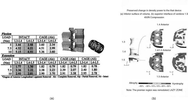
586 HUMAN SPINE, BIOMECHANICS OF
Figure 18. (a) The FE model of a ligamentous motion segment was used to predict load-displacement behavior of the segment following cage placement. Alc ¼ anterior longitudinal ligament completely removed/cut, Alp ¼ partially cut, and Ali ¼ intact; and (b) Percentage change in density of the bone surrounding the BAK cage. (Taken from Refs. 32,33, and 257.)
a hydrogel) (244,258,259). As a nucleus replacement, the implant can be inserted similar to a thoracolumbar interbody fusion device, either posteriorly or transversely. Two are inserted per disk level in a partly collapsed and dehydrated state, but would swell due to the strongly hygroscopic properties of the hyaluronic acid constituent. The designer expects the implant to swell enough to distract the segment while retain enough flexibility to allow a normal range of motion. An option is to include therapeutic agents in the gel that would be released by water flow in and out of the prosthesis according to external pressures.
Recent reports on biomechanical tests of the device show that it can produce some degree of stabilization and distraction. Loads of 7.5 N m and 200 N axial were applied to six L4-L5 specimens. Nucleotomized spines increased rotations by 12–18% depending on load orientation, but implanted spines (implant placed transversely) showed a change of 12% to þ2% from the intact with substantial reductions in neutral zone. Up to 2 mm of disk height was recovered by insertion. The implant, however, was implanted and tested in its no hydrated form. The biomechanics of the hydrated prosthesis may vary considerably from that of its desiccated form.
In Situ Curable Prosthetic Intervertebral Nucleus (PIN)
The device (Disc Dynamics, Inc, Minnetonka, MN) consists of a compliant balloon connected to a catheter (Fig. 19) (244,260). This is inserted and a liquid polymer injected into the balloon under controlled pressure inflating the balloon, filling the cavity, and distracting the interverteb-
ral disk. Within 5 min the polymer is cured. Five freshfrozen osteoligamentous three-segment human lumbar spines, screened for abnormal radiograph and low bone density, were used for the biomechanical study. The spines were tested under four conditions: intact, denucleated, implanted, and fatigued. Fatiguing was produced by cyclic loading from 250 to 750 N at 2 Hz for at least 100,000 cycles. Nuclectomy was performed through a 5.5 mm trephine hole in the right middle lateral side of the annulus. The device was placed in the nuclear cavity as described earlier. Following biomechanical tests, these specimens were radiographed and dissected to determine any structural damage inflicted during testing. Middle segment rotations generally increased with diskectomy, but were restored to the normal intact range with implantation. After fatiguing, rotations across the implanted segment increased. However, these were not more than, and often less than the intact adjacent segments. During polymer injection under compressive load the segment distracted as much as þ1.8 mm (av) at the disk center as determined by the surrounding gauges. Over 1.6 mm was maintained during polymer cure with compression. The immediate goals of a disk replacement system are to restore disk height and provide segment mobility without causing instability. This study showed that PIN device could reverse the destabilizing effects of a nuclectomy and restore normal segment stiffness. Significant increases in disk height can also be achieved. Implanting the majority of disk replacement systems requires significant annulus removal, this device requires minimal surgical compromise and has the potential to be performed arthroscopically.

HUMAN SPINE, BIOMECHANICS OF |
587 |
Artificial Disk
One of the most recent developments for nonfusion treatment alternatives is replacement of the intervertebral disk (244,261,262). The goal of this treatment alternative is to restore the original mechanical function of the resected disk. One of the stipulations of artificial disk replacement is that the remaining osseous spinal and paraspinal soft tissue components are not compromised by pathologic changes. Bao et al. (263) have classified the designs of total disk replacements into four categories: (1) low friction sliding surface; (2) spring and hinge systems; (3) contained fluid-filled chambers; and (4) disks of rubber and other elastomers. The former two designs seek to take advantage of the inherently high fatigue characteristics that all-metal designs afford. The latter two designs attempt to incorporate some of the viscoelastic and compliant properties that are exhibited by the normal, healthy intervertebral disk. Hedman et al. (264) outlined the major design criteria for intervertebral disk prosthesis: The disk must be able to maintain its mechanical integrity out to approximately 85 million cycles; consist of biocompatible materials; exist entirely within the normal disk space and maintain physiologic disk height; restore normal kinematic motion wherein the axes of each motion, especially sagittal plane motion, is correctly replicated; duplicate the intact disk stiffness in all three planes of rotation and compression; provide immediate and long-term fixation to bone; and, finally, provide failsafe mechanisms such that if an individual component of the design fails, catastrophic failure is not immediately imminent, and it does not lead to periimplant soft tissue damage. This is certainly one of the greatest design challenges that bioengineers have encountered to date. In the following, some of the methods are discussed that are being employed in an attempt to meet this rigorous challenge.
Figure 19. In situ curable prosthetic intervertebral nucleus (PIN) developed by Disc Dynamics, Inc. (Taken from Ref. 244.)
One of the available studies dealt iterative design of the artificial disk replacement based on measured biomechanical properties. Lee, Langrana and co-workers (265,266) looked at incorporating three different polymers into their prosthetic intervertebral disk design and tried to represent the separate components (annulus fibrosis and nucleus) of the normal disk in varying proportion. They loaded their designs under 800 N axial compression and in compres- sion-torsion out to 58. The results indicated that disks fabricated from homogeneous materials exhibited isotropy that could not replicate the anisotropic behavior of the normal human disk. Thus, 12 layers of fiber reinforcement were incorporated in an attempt to mimic the actual annulus fibrosis. This method did result in more closely approximating the mechanical properties of the normal disk. Through this method of redesign and testing, authors claim that eventually ‘‘a disk prosthesis that has mechanical properties comparable to the natural disk could be manufactured.’’
The FE analyses have also been recruited in an effort to perturbate design with an eye toward optimizing the mechanical behavior of artificial disks. Goel and associates modified a previously validated intact finite element model to create models implanted with a ball-and-cup and slip core-type artificial disk models via an anterior approach, Figs. 20 and 21 (244,245,261). To study surgical variables, small and large windows were cut into the annulus, and the implants were placed anteriorly and posteriorly within the disk space. The anterior longitudinal ligament was also restored. Models were subjected to either 800 N axial compression force alone or to a combination of 10 N m flexion–extension moments and 400 N axial preload. Implanted model predictions were compared with those of the intact model. The predicted rotations for the two disk implanted models were in agreement with the experimental data.

588 HUMAN SPINE, BIOMECHANICS OF
Figure 20. The intact finite element model of a ligamentous segment was modified to simulate the ball and socket type artificial disk implant. (Taken from Refs. 244,245.)
For the ball and socket design disk facet loads were more sensitive to the anteroposterior location of the artificial disk than to the amount of annulus removed. Under 800-N axial compression, implanted models with an anteriorly placed artificial disk exhibited facet loads 2.5 times greater than loads observed with the intact model, whereas posteriorly implanted models predicted no facet loads in compression. Implanted models with a posteriorly placed disk exhibited greater flexibility than the intact and implanted models with anteriorly placed disks. Restoration of the anterior longitudinal ligament reduced pedicle stresses, facet loads, and extension rotation to nearly intact levels. The models suggest that, by altering placement of the artificial disk in the anteroposterior direction, a surgeon can modulate motion-segment flexural stiffness and posterior load sharing, even though the specific disk replacement design has no inherent rotational stiffness.
The motion data, as expected, differed between the two disk designs (ball and socket, and slip core) and as compared to the intact as well, Fig. 22. Similar changes were observed for the loads on the facets, Fig. 23.
The experimentally validated finite element models of the intact and disk implanted L3-L5 segments revealed that both of these devices do not restore motion and loads across facets back to the intact case. (These design restore the intact biomechanics in a limited sense.) These differences are not only due to the size of the implants but the inherent design differences. Ball and socket design has a more ‘‘fixed’’ center of rotation as compared to the slip core design in which the COR undergoes a wider variation. Further complicating factor is the location of the disk within the annular space itself, a parameter under the control of the surgeon. Thus, it will be difficult to restore biomechanics of the segment back to normal using such designs. Only clinical follow up studies will provide the effects of such variations on the changes in spinal structures as a function of time.
More Recent and Future Initiatives
Although many of the well-accepted investigation techniques and devices have been discussed above, other
Figure 21. The intact finite element model of a ligamentous segment was modified to simulate the slip core type artificial disk implant. (Taken from Ref. 244.)
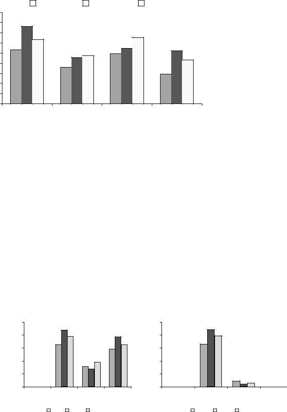
Rotation (˚)
HUMAN SPINE, BIOMECHANICS OF |
589 |
|
Intact |
|
Danek |
|
Slip-Core |
9 |
|
|
|
|
|
|
8 |
7.6 |
|
|
|
|
|
|
|
|
|
|
|
|
7 |
6.3 |
|
|
6.5 |
|
|
6 |
5.3 |
|
|
5.5 |
5.2 |
|
5 |
|
4.6 |
4.7 |
5.0 |
|
|
|
|
4.3 |
|
|||
|
|
|
|
|
|
|
4 |
|
3.5 |
|
|
|
|
|
|
|
|
3.0 |
|
|
3 |
|
|
|
|
|
|
|
|
|
|
|
|
|
2 |
|
|
|
|
|
|
1 |
|
|
|
|
|
|
0 |
|
|
|
|
|
Figure 22. Predicted rotations for the |
|
|
|
|
|
two disk designs, shown in Figs. 20 and |
|
|
Flexion |
Extension |
Right lateral |
Left axial rotation |
||
|
21, as compared to the intact. (Taken |
|||||
|
|
|
|
bending |
|
from Ref. 244.) |
techniques for the stabilization–fusion of the spine and nonfusion approaches are currently being investigated. These concepts are likely to play a significant role in future and are discussed. One such technique is vertebroplasty. Painful vertebral osteoporotic compression fractures leads to significant morbidity and mortality (263). Kyphoplasty and vertebroplasty are relatively new techniques that help decrease the pain and improve function in fractured vertebras.
Vertebroplasty is the percutaneous injection of PMMA cement into the vertebral body (263–269). While PMMA has high mechanical strength, it cures fast and thus allows only a short handling time. Other potential problems of using PMMA injection may include damage to surrounding tissues by a high polymerization temperature or by the unreacted toxic monomer, and the lack of long-term biocompatibility. Bone mineral cements, such as calcium carbonate and CaP, have longer working time and low thermal effect. They are also biodegradable while having
a good mechanical strength. However, the viscosity of injectable mineral cements is high, and the infiltration of these cements into vertebral body has been questioned. Lim et al. evaluated the compression strength of human vertebral bodies injected with a new calcium phosphate (CaP) cement with improved infiltration properties before compression fracture and also for vertebroplasty in comparison with PMMA injection (268). The bone mineral densities of 30 vertebral bodies (T2-L1) were measured using dual-energy X-ray absorptiometry. Ten control specimens were compressed at a loading rate of 15 mm/min to 50% of their original height. The other specimens had 6 mL of PMMA (n ¼ 10) or the new CaP (n ¼ 10) cement injected through the bilateral pedicle approach before being loaded in compression. Additionally, after the control specimens had been compressed, they were injected with either CaP (n ¼ 5) or PMMA (n ¼ 5) cement using the same technique, to simulate vertebroplasty. Loading experiments were repeated with the displacement control of 50% vertebral
Right facet load |
Left facet load |
comparison |
comparison |
|
|
Right facet loads at L3-L4 |
|
|
|
|
|
10 Nm + 400 N comparision |
|
|
|
|
250 |
220 |
|
|
250 |
(N) |
|
|
|
|
|
200 |
196 |
192 |
(N) |
200 |
|
joint |
|
165 |
161 |
joint |
|
150 |
146 |
150 |
|||
across |
|
|
across |
||
100 |
92 |
|
100 |
||
7970 |
|
||||
|
|
|
|||
Force |
50 |
|
|
Force |
50 |
|
|
|
|
||
|
0 |
|
|
|
0 |
Left facet loads at L3-L4 10 Nm + 400 N comparision
220 |
|
|
196 |
|
|
165 |
|
|
19 |
9 |
12 |
Flexion Extension Right Lateral Left Axial |
Flexion |
|
Extension Right Lateral |
Left Axial |
||||||||||
|
|
|
|
Bending Rotation |
|
|
|
|
Bending |
Rotation |
||||
|
|
Intact |
|
Danek |
|
Slip-Core |
|
|
Intact |
|
Danek |
|
Slip-Core |
|
|
|
|
|
|
|
|
|
|
||||||
|
|
|
|
|
|
|
|
|
||||||
Figure 23. Predicted facet loads for the two disk designs, shown in Figs. 20 and 21, as compared to the intact. (Taken from Ref. 244.)
590 HUMAN SPINE, BIOMECHANICS OF
height. Load to failure was compared among groups and analyzed using analysis of variance. Mean bone mineral densities of all five groups were similar and ranged from 0.56 to 0.89 g cm 2. The size of the vertebral body and the amount of cement injected were similar in all groups. Load to failure values for PMMA, the new CaP, and vertebroplasty PMMA were significantly greater than that of control. Load to failure of the vertebroplasty CaP group was higher than control but not statistically significant. The mean stiffness of the vertebroplasty CaP group was significantly smaller than control, PMMA, and the new CaP groups. The mean height gains after injection of the new CaP and PMMA cements for vertebroplasty were minimal (3.56 and 2.01%, respectively). Results of this study demonstrated that the new CaP cement can be injected and infiltrates easily into the vertebral body. It was also found that injection of the new CaP cement can improve the strength of a fractured vertebral body to at least the level of its intact strength. Thus, the new CaP cement may be a good alternative to PMMA cement for vertebroplasty, although further in vitro, in vivo animal and clinical studies should be done. Furthermore, the new CaP may be more effective in augmenting the strength of osteoporotic vertebral bodies, and for preventing compression fractures considering our biomechanical testing data and the known potential for biodegradability of the new CaP cement. Belkof et al. (266) found that the injection of either Orthocomp or Simplex P resulted in vertebral body strengths that were significantly greater than initial strength values. Vertebral bodies augmented with Orthocomp recovered their initial stiffness; and, vertebral bodies augmented with Simplex P were significantly less stiff than they were in their initial condition. However, these biomechanical results have yet to be substantiated in clinical studies.
Previous biomechanical studies have shown that injections of 8–10 mL of cement during vertebroplasty restore or increase vertebral body strength and stiffness; however, the dose-response association between cement volume and restoration of strength and stiffness is unknown. Belkof et al. (266) investigated the association between the volume of cement injected during percutaneous vertebroplasty and the restoration of strength and stiffness in osteoporotic vertebral bodies. Two investigational cements were studied: Orthocomp (Orthovita, Malvern, PA) and Simplex 20 (Simplex P with 20% by weight barium sulfate. Compression fractures were experimentally created in 144 vertebral bodies (T6-L5) obtained from 12 osteoporotic spines harvested from female cadavers. After initial strength and stiffness were determined, the vertebral bodies were stabilized using bipedicular injections of cement totaling 2, 4, 6, or 8 mL and recompressed, from which post-treatment strength and stiffness were measured. Strength and stiffness were considered restored when post-treatment values were not significantly different from initial values. Strength was restored for all regions when 2 mL of either cement was injected. To restore stiffness with Orthocomp, the thoracic and thoracolumbar regions required 4 mL, but the lumbar region required 6 mL. To restore stiffness with Simplex 20, the thoracic and lumbar regions required 4 mL, but the thoracolumbar region required 8 mL. These data provide
guidance on the cement volumes needed to restore biomechanical integrity to compressed osteoporotic vertebral bodies.
Liebschner et al. undertook a finite element based biomechanical study to provide a theoretical framework for understanding and optimizing the biomechanics of vertebroplasty, especially the effects of volume and distribution of bone cement on stiffness recovery of the vertebral body, just like the preceding experimental study (269). An experimentally calibrated, anatomically accurate finiteelement model of an elderly L1 vertebral body was developed. Damage was simulated in each element based on empirical measurements in response to a uniform compressive load. After virtual vertebroplasty (bone cement filling range of 1–7 cm3) on the damaged model, the resulting compressive stiffness of the vertebral body was computed for various spatial distributions of the filling material and different loading conditions. Vertebral stiffness recovery after vertebroplasty was strongly influenced by the volume fraction of the implanted cement. Only a small amount of bone cement (14% fill or 3.5 cm3) was necessary to restore stiffness of the damaged vertebral body to the predamaged value. Use of a 30% fill increased stiffness by > 50% compared with the predamaged value. Whereas the unipedicular distributions exhibited a comparative stiffness to the bipedicular or posterolateral cases, it showed a medial-lateral bending motion (toggle) toward the untreated side when a uniform compressive pressure load was applied. Only a small amount of bone cement (15% volume fraction) is needed to restore stiffness to predamage levels, and greater filling can result in substantial increase in stiffness well beyond the intact level. Such overfilling also renders the system more sensitive to the placement of the cement because asymmetric distributions with large fills can promote single-sided load transfer and thus toggle. These results suggest that large fill volumes may not be the most biomechanically optimal configuration, and an improvement might be achieved by use of lower cement volume with symmetric placement. These theoretical findings support the experimental observations described in the proceeding paragraph, except these authors did not analyze the relationship between cement type and volume needed to restore strength.
Hitchon et al. compared the stabilizing effects of the HA product, with PMMA in an experimental compression fracture of L1 (268). No significant difference between the HA and PMMA cemented-fixated spines was demonstrated in flexion, extension, left lateral bending, or rightand left-axial rotation. The only difference between the two cements was encountered before and after fatiguing in right lateral bending (p 4 0.05). The results of this study suggest that the same angular rigidity can be achieved by using either HA or PMMA. This is of particular interest because HA is osteoconductive, undergoes remodeling, and is not exothermic.
Advances in the surgical treatment of spinal etiologies continues to evolve with the rapid progression of technology. The advent of robotics, Microelectromechanical systems (MEMS) (270), novel biomaterials, and genetic and tissue engineering are revolutionizing spinal medicine, Novel biomaterials, also termed ‘‘smart biomaterials’’ that are capable of conforming or changing their mechanical
properties in response to different loading paradigms are being investigated for their use in spinal implant design. The rapidly advancing field of tissue engineering opens new possibilities to solving spine problems. By seeding and growing intervertebral disk cells, it could be possible to grow a new bioartificial disk, to be implanted in to the spine. Studies are in progress at a number of centers, including our own (269).
CONCLUSION
The stability (or instability) of the human spine is integral to the diagnosis and treatment of patients with low back pain. The stability of the lumbar spine as portrayed by its motion characteristics can be determined through the use of clinical and radiographic criteria or other methods of determining the orientation of one spinal vertebra with respect to another. The instability can be the result of injury, disease, and many other factors, including surgery. Therefore, it is necessary to become familiar with recent findings and suggestions that deal with the instability that can result from such procedures. The prevalence of spinal fusion and stabilization procedures to restore spinal stability and host of other factors is continuously increasing. This article has presented many of the contemporary biomechanical issues germane to stabilization and fusion of the spine. Because of the wide variety of devices available, various testing protocols have been developed in an attempt to describe the mechanical aspects of these devices. These investigations reveal comparative advantages (and disadvantages) of the newer designs to existing hardware. Subsequent in vivo testing, specifically animal models, provides data on the performance of the device in a dynamic physiologic environment. All of the testing, in vitro and in vivo, helps to build confidence that the instrumentation is safe for clinical trial. Future biomechanical work is required to produce newer devices and optimize existing ones, with an eye toward reducing the rates of nonfusion and pseudoarthrosis. In addition, novel devices and treatments that seek to restore normal spinal function and loading patterns without fusion continue to necessitate advances in biomechanical methods. These are the primary challenges that need to be incorporated in future biomechanical investigations. Finally, one has to gain understanding of the effects of devices at the cellular level and one must undertake outcome assessment studies to see if the use of instrumentation is warranted for the enhancement of the fusion process.
ACKNOWLEDGMENTS
Manuscript is based on the work sponsored by various funding agencies over the last 20 years. Thanks also to a large number of coinvestigators who have contributed to the original work reported in this article.
BIBLIOGRAPHY
1.Goel VK, Weinstein JN. Clinical Biomechanics of the Lumbar Spine. Boca Raton (FL): CRC Press; 1990.
HUMAN SPINE, BIOMECHANICS OF |
591 |
2.White AAA, Panjabi MM. Clinical Biomechanics of Spine. New York: Lippincot. 2nd ed.; 1990.
3.Doherty BJ, Heggeness MH. Quantitative anatomy of the second cervical vertebra. Spine 1995;20:513–517.
4.(a) Yoganandan N, Halliday A, Dickman C, Benzel E. Practical anatomy and fundamental biomechanics, in Spine Surgery: Techniques, Complication Avoidance, and Management. In: Benzel EC, editor. New York: Churchill Livingstone; 1999. p 93–118. (b) Clausen JD. Experimental & Theoretical Investigation of Cervical Spine Biomechanics— Effects of Injury and Stabilization. Ph.D. dissertation, University of Iowa, Iowa City (IA) 52242; 1996. (c) Puttlitz CM. A Biomechanical Investigation of the Craniovertebral Junction. Ph.D. dissertation, University of Iowa, Iowa City (IA) 52242; 1999. (d) Scifert JL. Biomechanics of the Cervical Spine. Ph.D. dissertation, University of Iowa, Iowa City (IA) 52242; 2000. (e) Goel VK, Panjabi MM, Kuroki H, Rengachary S, McGowan D, Ebraheim N. Biomechanical Considerations— Spinal Instrumentation. ISSLS Book. 2003. (f) Kuroki H, Holekamp S, Goel V, Panjabi M, Ebraheim N, Singer K. Biomechanics of Spinal Deformity in Inflammatory Disease. book chapter submitted; 2003. (g) Goel VK, Dooris AP, McGowan D, Rengachary S. Biomechanics of the Disk. In: Lewandrowski K-U, Yaszemski MJ, White III AA, Trantolo DJ, Wise DL, editors. Advances in Spinal Fusion—Molecular Science, Biomechanics, and Clinical Management. Somerville (CA): M&N Toscano; 2003. (h) Panjabi MM, Yue JJ, Dvorak J, Goel V, Fairchild T, White AA. Chapt. 4 Cervical Spine Kinematics and Clinical Instability. Cervical Spine Research Society; 2003 (submitted).
5.Xu R, Nadaud MC, Ebraheim NA, Yeasting RA. Morphology of the second cervical vertebra and the posterior projection of the C2 pedicle axis. Spine 1995;20:259–263.
6.Heggeness MH, Doherty BJ. The trabecular anatomy of the axis. Spine 1993;18:1945–1949.
7.Watkins RG. Cervical Spine Injuries in Athletes. In: Clark CR, editor. The cervical spine. Philadelphia: LippincottRaven; 1998. p 373–386.
8.Penning L. Differences in anatomy, motion, development, and aging of the upper and lower cervical disk segments. Clin Biomech 1988;3:337–347.
9.Pooni J, Hukins D, Harris P, Hilton R, Davies K. Comparison of the structure of human intervertebral disks in the cervical, thoracic and lumbar regions of the spine. Surg Rad Anat 1986;8:175–182.
10.Tulsi R, Perrett L. The anatomy and radiology of the cervical vertebrae and the tortuous vertebral artery. Aust Rad 1975; 19:258–264.
11.Frykholm R. Lower cervical vertebrae and intervertebral disks. Surgical anatomy and pathology. Acta Chir Scand 1951;101:345–359.
12.Hall M. Luschka’s Joint. Springfield (IL): Charles C. Thomas; 1965.
13.Hardacker J, Shuford R, Capicotto P, Pryor P. Radiographic standing cervical segmental alignment in adult volunteers without neck symptoms. Spine 1997;22(13):1472–1480.
14.Harrison D, Janik T, Troyanovich S, Harrison D, Colloca C. Evaluation of the assumptions used to derive an ideal normal cervical spine model. JMPT 1997;20(4):246–256.
15.Harrison D, Janik T, Troyanovich S, Holland B. Comparisons of lordotic cervical spine curvatures to a theoretical ideal model of the static sagittal cervical spine. Spine 1996;21(6): 667–675.
16.Rosenberg LC. Proteoglycans. In: Owen R, Goodfellow J, Bullough P, editors. Scientific Foundations of Orthopaedics and Traumatology. Philadelphia: WB Saunders; 1980. p 36–42.
592HUMAN SPINE, BIOMECHANICS OF
17.Humzah M, Soames R. Human intervertebral disk: structure and function. Anatomical Rec 1988;220:337–356.
18.Oda J, Tanaka H, Tsuzuki N. Intervertebral disk changes with aging of the human cervical vertebra: from neonate to the eighties. Spine 1988;13:1205–1211.
19.Alker GJ, Oh YS, Leslie EV. High cervical spine and craniocervical junction injuries in fatal traffic accidents: a radiological study. Orthop Clin NA 1978;9:1003–1010.
20.Freeman L, Wright T. Experimental observations of concussion and contusion of the spinal cord. Ann Surg 1953; 137(4): 433–443.
21.Hirsch C, Galante J. Laboratory conditions for tensile tests in annulus fibrosis from human intervertebral disks. Acta Orthop Scand 1967;38:148–162.
22.Singer KP, Breidahl PD, Day RE. Posterior element variation at the thoracolumbar transition. A morphometric study using computed tomography. Clin Biomech 1989;4:80–86.
23.Panjabi MM, Thibodeau LL, Crisco III JJ, et al. What constitutes spinal instability? Clin Neurosurg 1988; 34: 313–339.
24.Putz R. The detailed functional anatomy of the ligaments of the vertebral column. Anatomischer Anzeiger 1992;173:40–47.
25.Gilbertson LG. Mechnism of fracture and biomechanics of orthosis in thoracolumbar region. Ph.D. dissertation, University of Iowa (IA); 1993.
26.Ikegawa S, et al. The effect of joint angle on cross sectional area and muscle strength of human elbow flexors, Human Kinetics. Biomechanics SA: Champaign; 1979. p 35–44.
27.Macintosh JE, Bogduk N, Pearcy MJ. The effects of flexion on the geometry and actions of the lumbar erector spinae. Spine 1993;18:884–893.
28.White AA, et al. Spinal stability. Evaluation and treatment. instr course lect. AAOS 1981;30:457–484.
29.Penning L, Normal Kinematics of the Cervical Spine, Clinical Anatomy and Management of Cervical Spine Pain. In: Giles SK, editor. Oxford (UK): Butterworth Heinemann; 1998. p 53–70.
30.Panjabi MM, Dvorak J, Sandler AJ, Goel VK, White AA. Cervical Spine Kinematics and Clinical Instability. In: CR C, editor. The Cervical Spine. Philadelphia: Lippincott-Raven; 1998. p 53–77.
31.Panjabi MM, Dvorak J, Duranceau J, Yamamoto I, Gerber M, Rauschning W, Bueff HU. Three dimensional movements of the upper cervical spine. Spine 1988;13:726–730.
32.Goel VK, Clark CR, Gallaes K, Liu YK. Moment–rotation relationships of the ligamentous occipitoatlanto-axial complex. Spine 1988;21:673–680.
33.Moroney S, Schultz A, Miller J, Andersson G. Load-displace- ment properties of lower cervical spine motion segments. J Biomech 1988;21(9):769–779.
34.Lysell E. Motion in the cervical spine. Ph.D. dissertation. Acta Orthop Scand (123 Suppl); 1969.
35.Bernhardt M, White AA, Panjabi MM, McGowan DP. Biomechanical considerations of spinal stability. The Spine. 3rd ed. Philadelphia: WB Saunders Company; 1992. p 1167– 1195.
36.Pearcy MJ. Stereoradiography of lumbar spine motion. Acta Orthop Scand 1985;56(212 Suppl).
37.Calve J, Galland M. Physiologie Pathologique Du Mal De Pott. Rev Orthop 1930;1:5.
38.Rolander SD. Motion of the lumbar spine with special reference to the stabilizing effect of the posterior fusion. Scta Ortho Scand 1966;90(Suppl):1–114.
39.Oda T, Panjabi MM, Crisco JJ, Oxland T, Katz L, Nolte L-P. Experimental study of atlas injuries II—Relevance to clinical diagnosis and treatment. Spine 1991;16:S466–473.
40.Oda T, Panjabi MM, Crisco JJ, Oxland TR. Multidirectional instabilities of experimental burst fractures of the atlas. Spine 1992;17:1285–1290.
41.Jefferson G. Fracture of the atlas vertebra: report of four cases, and a review of thos previously recorded. Br J Surg 1920;7:407–422.
42.Heller JG, Amrani J, Hutton WC. Transverse ligament fail- ure—a biomechanical study. J Spinal Disord 1993;6: 162– 165.
43.Goel VK, et al. Ligamentous laxity across CO-C1-C2 complex: axial torque-rotation characteristics until failure. Spine 1990;15:990–996.
44.Chang H, Gilbertson LG, Goel VK, Winterbottom JM, Clark CR, Patwardhan A. Dynamic response of the occipito-atlanto- axial (C0-C1-C2) complex in right axial rotation. J Orth Res 1992;10:446–453.
45.Doherty BJ, Heggeness MH, Esses SI. A biomechanical study of odontoid fractures and fracture fixation. Spine 1993;18:178–184.
46.Anderson LD, D’Alonzo RT. Fractures of the odontoid process of the axis. J Bone Joint Surg 1974;56-A:1663–1674.
47.Schatzker J, Rorabeck CH, Waddell JP. Fractures of the dens. J Bone Joint Surg 1971;53-B:392–405.
48.Clark CR, White AA. Fractures of the dens. JBJS 1985;67- A:1340–1348.
49.Althoff B. Fracture of the odontoid process. Acta Orthop Scand 1979;177(Suppl):1–95.
50.Mouradian WH, Fietti VG, Cochran GVB, Fielding JW, Young J. Fractures of the odontoid: a laboratory and clinical study of mechanisms. Orthop Clinics of NA 1978;9:985–1001.
51.Puttlitz CM, Goel VK, Clark CR, Traynelis VC. Pathomechanism of Failures of the Odontoid. Spine 2000;25:2868– 2876.
52.Goel VK, Montgomery RE, Grosland NM, Pope MH, Kumar S. Ergonomic factors in the work place contribute to disk degeneration. In: Kumar S, editor. Biomechanics in Ergonomics. Taylor & Francis; 1999. p 243–267.
53.Liu YK, Njus G, Buckwalter J, Wakano K. Fatigue response of lumbar intervertebral joints under axial cyclic loading. Spine 1983;6:857.
54.Hooper DM. Consequences of asymmetric lifting on external and internal loads at the L3–5 lumbar levels. Ph.D. dissertation, Iowa City (IA): University of Iowa; 1996.
55.Kelsey JL. An epidemiological study of acute herniated lumbar intervertebral disk. Rehum Rehabil 1975;14:144.
56.Panjabi MM, Anderson GBJ, Jorneus L, Hult E, Matteson L. In vivo measurements of spinal column vibrations. JBJS 1986;68A:695.
57.Wilder DG, Woodworth BB, Frymoyer JW, Pope MH. Vibration and the human spine. Spine 1982;7:243.
58.Liu YK, Goel VK, DeJong A, Njus G, Nishiyama K, Buckwalter J. Torsional fatigue of the lumbar intervertebral joints. Spine 1985;10:894–900.
59.Kong W-Z, Goel VK. Ability of the finite element models to predict response of the human spine in sinusoidal vertical vibration. Spine 2003;28:1961–1967.
60.Furlong DR, Palazotto AN. A finite element analysis of the influence of surgical herniation on the viscoelastic properties of the intervertebral disk. J Biomech 1983;16:785.
61.Lee C-K, Kim Y-E, Jung J-M, Goel VK. Impact response of the vertebral segment using a finite element model. Spine 2000;25:2431–2439.
62.Dvorak J, Hayek J, Zehnder R. CT-functional diagnostics of the rotatory instability of the upper cervical spine: part 2. An evaluation on healthy adults and patients with suspected instability. Spine 1987;12:726–731.
63.Dvorak J, Penning L, Hayek J, Panjabi MM, Grob D, Zehnder R. Functional diagnostics of the cervical spine using computer tomography. Neuroradiology 1988;30:132– 137.
64.Crisco JJ, Takenori O, Panjabi MM, Bueff HU, Dovrak J, Grob D. Transections of the C1-C2 joint capsular ligaments in the cadaveric spine. Spine 1991;16:S474–S479.
65.Fielding JW. Cineroentgenography of the normal cervical spine. J Bone Joint Surg 1957;39-a:1280–1288.
66.Puttlitz CM, Goel VK, Clark CR, Traynelis VC, Scifert JL, Grosland NM. Biomechanical rationale for the pathology of rheumatoid arthritis in the craniovertebral junction. Spine 2000;25:1607–1616.
67.Panjabi MM, White AA, Keller D, Southwick WO, Friedlaender G. Stability of the cervical spine under tension. J Biomech 1978;11:189–197.
68.Goel VK, Clark CR, Harris KG, Schulte KR. Kinematics of the cervical spine: effects of multiple total laminectomy and facet wiring. J Orthop Res 1988;6:611–619.
69.Goel VK, Clark CR, Harris KG, Kim YE, Schulte KR. Evaluation of effectiveness of a facet wiring technique: an in vitro biomechanical investigation. Ann Biomed Eng 1989;17:115– 126.
70.Goel VK, Clausen JD. Prediction of load sharing among spinal components of a C5–C6 motion segment using the finite element approach. Spine 1998;23:684–691.
71.Clausen JD, Goel VK, Traynelis VC, Scifert JL. Uncinate processes and luschka’s joints influence the biomechanics of the cervical spine-quantification using a finite element model of the C5-C6 segment. J Orth Res 1997;15:342–347.
72.Edwards WT, Zheng Y, Ferrara LA, Yuan HA. Structural features and thickness of the vertebral cortex in the thoracolumbar spine. Spine 2001;26(2):218–225.
73.Goel VK, Monroe BT, Gilbertson LG, Brinckmann P. Interlaminar shear stresses and laminae separation in a disk: finite element analysis of the L3-4 motion segment subjected to axial compressive loads. Spine 1995;20:689–698. (1994 Volvo Award Paper).
74.Goel VK, Kim YE. Effects of injury on the spinal motion segment mechanics in the axial compression mode. Clin Biomech 1989;4:161–167.
75.Posner I, White AA, Edwards WT, et al. A biomechanical analysis of clinical stability of the lumbar lumbrosacral spine. Spine 1982;7:374–389.
76.Kong WZ, Goel VK, Gilbertson LG, et al. Effects of muscle dysfunction on lumbar spine mechanics–a finite element study based on a two motion segments model. Spine 1996; 21:2197.
77.Kong W, Goel V, Weinstein J. Role of facet morphology in the etiology of degenerative spondylolisthesis in the presence of muscular activity. 41st Annual Meeting. Orlando, FL: Orthopaedic Research Society; Feb 13–16, 1995.
78.Lipson JL, Muir H. Proteoglycans in experimental intervertebral disk degeneration. Spine 1981;6:194–210.
79.Raynor RB, Moskovich R, Zidel P, Pugh J. Alterations in primary and coupled neck motions after facetectomy. J Neurosurg 1987;12:681–687.
80.Schulte KR, Clark CR, Goel VK. Kinematics of the cervical spine following discectomy and stabilization. Spine 1989;14: 1116–1121.
81.Martins A. Anterior cervical discectomy with and without interbody bone graft. J Neurosurg 1976;44:290–295.
82.Wilson D, Campbell D. Anterior cervical discectomy without bone graft. Neurosurgery 1977;47:551–555.
83.Goel VK, Nye TA, Clark CR, Nishiyama K, Weinstein JN. A technique to evaluate an internal spinal device by use of the
HUMAN SPINE, BIOMECHANICS OF |
593 |
Selspot system: an application to Luque closed loop. Spine 1987;12:150–159.
84.Zdeblick TA, Zou D, Warden KE, McCabe R, Kunz D, Vanderby R. Cervical stability after foraminotomy. A biomechanical in vitro analysis. J Bone Joint Surg [Am] 1992; 74:22–27.
85.Zdeblick TA, Abitbol JJ, Kunz DN, McCabe RP, Garfin S. Cervical stability after sequential capsule resection. Spine 1993;18:2005–2008.
86.Cusick JF, Yoganandan N, Pintar F, Myklebust J, Hussain H. Biomechanics of cervical spine facetectomy and fixation techniques. Spine 1988;13:808–812.
87.Voo LM, Kumaresan S, Yoganandan N, Pintar FA, Cusick JF. Finite element analysis of cervical facetectomy. Spine 1997;22:964–9.
88.Nowinski GP, Visarius H, Nolte LP, Herkowitz HN. A biomechanical comparison of cervical laminaplasty and cervical laminectomy with progressive facetectomy. Spine 1993;18: 1995–2004.
89.Goel VK, Clark CR, Harris KG, Schulte KR. Kinematics of the cervical spine: effects of multiple total laminectomy and facet wiring. J Orthop Res 1988;6:611–619.
90.Goel VK, Clark CR, McGowan D, Goyal S. An in-vitro study of the kinematics of the normal, injured and stabilized cervical spine. J Biomech 1984;17:363–376.
91.Bell DF, Walker JL, O’Connor G, Tibshirani R. Spinal deformity after multiple-level cervical laminectomy in children. Spine 1994;19:406–411.
92.Lee S-J, Harris KG, Nassif J, Goel VK, Clark CR. In vivo kinematics of the cervical spine; part I: development of a roentgen stereophotogrammetric technique using metallic markers and assessment of its accuracy. J Spinal Disord 1993;6:522–534.
93.Lee S-J. Three-dimensional analysis of post-operative cervical spine motion using simultaneous roentgen stereophotogrammetry with metallic markers. Ph.D. dissertation, Iowa City (IA): University of Iowa; 1993.
94.Kumaresan S, Yoganandan N, Pintar FA, Maiman DJ, Goel VK. Contribution of disk degeneration to osteophyte formation in the cervical spine—A biomechanical investigation. J Orth Res 2001;19(5):977–984.
95.Kubo S, Goel VK, Yang S-J, Tajima N. Biomechanical comparison of cervical double door laminoplasty using hydroxyapatite spacer. Spine 2003;28(3):227–234.
96.Kubo S, Goel VK, Tajima N. The biomechanical effects of multilevel posterior foraminotomy and foraminotomy with double door laminoplasty. J Spinal Disorders 2002;15:477– 485.
97.Panjabi MM. Low back pain and spinal instability. In: Weinstein JN, Gordon SL, editors. Low back pain: a scientific and clinical overview. San Diego (CA): American Academy of Orthopaedic Surgeons; 1996. p 367–384.
98.Panjabi MM, Kaigle AM, Pope MH. Degeneration, injury, and spinal instability. In: Wiesel SW, et al., editors. The lumbar spine. 2nd ed. Volume 1, Philadelphia, PA: W.B. Saunders; 1996. p 203–211.
99.Goel VK, et al. Kinematics of the whole lumbar spine—effect of discectomy. Spine 1985;10:543–554.
100.Watters WC, Levinthal R. Anterior cervical discectomy with and without fusion–results, complications, and long-term follow-up. Spine 1994;19:2343.
101.Oxland TR, Teija L, Bernhard J, Peter C, Kurt L, Philippe J, Lutz-P N. The relative importance of vertebral bone density and disk degeneration in spinal flexibility and interbody implant performance An in vitro study. Spine 1996;21(22): 2558–2569.
594HUMAN SPINE, BIOMECHANICS OF
102.Fraser RD. Interbody, posterior, and combined lumbar fusions. Spine 1995;20:167S.
103.Goel VK, Gilbertson LG. Basic science of spinal instrumentation. Clin Orthop 1987;335:10.
104.Penta M, Fraser RD. Anterior lumbar interbody fusion–a minimum 10 year follow-up. Spine 1997;22:2429.
105.Goel VK, Pope MH. Biomechanics of fusion and stabilization. Spine 1995;20:35S.
106.Purcell GA, Markolf KL, Dawson EG. Twelfth thoracic-first lumbar vertebral mechanical stability of fractures after Harrington-rod instrumentation. J Bone Joint Surg Am 1981;63:71.
107.Lehman RA, Kuklo TR, O-Brien MF. Biomechanics of thoracic pedicle screw fixation. Part I–Screw biomechanics. Seminars in Spine Surgery 2002;14(1):8–15.
108.Pfeiffer M, et al. Effect of specimen fixation method on pullout tests of pedicle screws. Spine 1996;21:1037.
109.Pfeiffer M, Hoffman H, Goel VK, et al. In vitro testing of a new transpedicular stabilization technique. Eur Spine J 1997;6:249.
110.Carlson GD, et al. Screw fixation in the human sacrum–an in vitro study of the biomechanics of fixation. Spine 1992;17:S196.
111.Ryken TC, Clausen John D, Traynelis Vincent C, Goel Vijay
K.Biomechanical analysis of bone mineral density, insertion technique, screw torque, and holding strength of anterior cervical plate screws. J Neurosurg 1995;83:324–329.
112.Choi W, Lee S, Woo KJ, Koo KJ, Goel V. Assessment of pullout strengths of various pedicle screw designs in relation to the changes in the bone mineral density. 48th Annual Meeting, Dallas, TX: Orthopedic Research Society; Feb. 10– 13, 2002.
113.Lim TH, et al. Prediction of fatigue screw loosening in anterior spinal fixation using dual energy x-ray absorptiometry. Spine 1995 Dec 1; 20(23):2565–2568; discussion 2569.
114.Hasagawa, et al. An experimental study of a combination method using a pedicle screw and laminar hook for the osteoporotic spine. Spine 1997; 22:958.
115.McLain RF, Sparling E, Benson DR. Early failure of shortsegment pedicle instrumentation for thoracolumbar fractures. J Bone Joint Surg Am 1993;75:162.
116.Bu¨ hler DW, Berlemann U, Oxland TR, Nolte L-P. Moments and forces during pedicle screw insertion in vitro and in vivo measurements. Spine 23(11):1220–1227.
117.Goel VK, Grosland NM, Scifert JL. Biomechanics of the lumbar disk. J Musculoskeletal Res 1997;1:81.
118.Lund T, Oxland TR, Jost B, Cripton P, Grassmann S, Etter C, Nolte LP. Interbody cage stabilisation in the lumbar spine: biomechanical evaluation of cage design, posterior instrumentation and bone density. J Bone Joint Surg Br 1998 Mar; 80(2):351–359.
119.Rapoff AJ, Ghanayem AJ, Zdeblick TA. Biomechanical comparison of posterior lumbar interbody fusion cages. Spine 1997;22:2375.
120.Steffen T, Tsantrizos A, Aebi M. Effect of implant design and endplate preparation on the compressive strength of interbody fusion construct. Spine 2000;25(9):1077–1084.
121.Brooke NSR, Rorke AW, King AT, et al. Preliminary experience of carbon fibre cage prosthesis for treatment of cervical spine disorders. Br J Neurosurg 1997;11:221.
122.Ketller A, Wilke HJ, Dietl R, Krammer M, Lumenta C, Claes
L.Stabilizing effect of posterior lumbar interbody fusion cages before and after cyclic loading. J Neurosurg 2000;92(1 Suppl):87–92.
123.Janssen ME, Nguyen, Beckham C, Larson R. A Biological cage. Eur Spine J 2000;9(1 Suppl):S102–S109.
124.Murakami H, Boden SD, Hutton WC. Anterior lumbar interbody fusion using a barbell-shaped cage: A biomechanical comparison. J Spinal Disord 2001;14(5):385–392.
125.Murakami H, Horton WC, Kawahara N, Tomita K, Hutton WC. Anterior lumbar interbody fusion using two standard cylindrical threaded cages, a single mega-cage, or dual nested cages: A biomechanical comparison. J Orthop Sci 2001;6(4):343–348.
126.Wang J, Zou D, Yuan H, Yoo J. A biomechanical evaluation of graft loading characteristics for anterior cervical discectomy and fusion. Spine 1998;23(22):2450–2454.
127.Cheng B, Moore D, Zdeblick T. Load sharing characteristics of two anterior cervical plate systems. in 25th Annual Meeting of the Cervical Spine Research Society;. 1997. Rancho Mirage (CA).
128.Rapoff A, O’Brien T, Ghanayem A, Heisey D, Zdeblick T. Anterior cervical graft and plate load sharing. J Spinal Disorders 1999;12(1):45–49.
129.An H, et al. Effect of endplate conditions and bone mineral density on the compressive strength of the graft-endplate interphase in the cervical spine. in 14th Annual Meeting of the North American Spine Society. Chicago Hilton and Towers; 1999.
130.Dietl R, Krammer HJ, Kettler M, Wilke A, Claes H-J, Lumenta L, Christianto B. Pullout test with three lumbar interbody fusion cages. Spine 2002;27(10):1029–1036.
131.Clausen JD, et al. A protocol to evaluate semi-rigid pedicle screw systems. J Biomech Eng 1997; 119:364.
132.Cunningham BW, et al. Static and cyclic biomechanical analysis of pedicle screw constructs. Spine 1993;18: 1677.
133.Goel VK, Winterbottom JM, Weinstein JN. A method for the fatigue testing of pedicle screw fixation devices. J Biomech 1994;27:1383.
134.Chang KW, et al. A comparative biomechanical study of spinal fixation using the combination spinal rod plate and transpedicular screw fixation system. J Spinal Disord 1989;1:257.
135.Panjabi MM. Biomechanical evaluation of spinal fixation devices: Part I. A conceptual framework. Spine 1988; 13(10):1129–1134.
136.Panjabi MM, Goel VK. Adjacent-Level Effects: Design of a new test protocol and finite element model simulations of disk replacement. In: Goel K, Panjabi MM, editors. Roundtables in Spine Surgery; Spine Biomechanics: Evaluation of Motion Preservation Devices and Relevant terminology, Chapt. 6. Vol 1, Issue 1, St. Louis: Quality Medical Publishing; 2005.
137.Patwardhan AG, et al. A follower load increases the loadcarrying capacity of the lumbar spine in compression. Spine 1999;24:1003–1009.
138.Cusick J, Pintar F, Yoganandan N, Baisden J. Wire fixation techniques of the cervical facets. Spine 1997;22(9):970– 975.
139.Fuji T, et al. Interspinous wiring without bone grafting for nonunion or delayed union following anterior spinal fusion of the cervical spine. Spine 1986;11(10):982–987.
140.Garfin S, Moore M, MarshallL. Amodifiedtechnique for cervical facet fusions. Clin Orthoped Rel Res 1988;230:149–153.
141.Geisler F, Mirvis S, Zrebeet H, Joslyn J. Titanium wire internalfixation for stabilization of injury of thecervical spine: clinical results and postoperative magnetic resonance imaging of the spinal cord. Neurosurgery 1989;25(3):356–362.
142.Scuderi G, Greenberg S, Cohen D, Latta L, Eismont F. A biomechanical evaluation of magnetic resonance imaging– compatible wire in cervical spine fixation. Spine 1993; 18(14):1991–1994.
143.Stathoulis B, Govender S. The triple wire technique for bifacet dislocation of the cervical spine. Injury 1997; 28(2):123–125.
144.Weis J, Cunningham B, Kanayama M, Parker L, McAfee P. In vitro biomechanical comparison of multistrand cables with conventional cervical stabilization. Spine 1996; 21(18):2108–2114.
145.Abumi K, Panjabi M, Duranceu J. Biomechanical evaluation of spinal fixation devices. Part III. Stability provided by six spinal fixation devices and interbody bone graft. Spine 1989;14:1239–1255.
146.Anderson P, Henley M, Grady M, Montesano P, Winn R. Posterior cervical arthrodesis with AO reconstruction plates and bone graft. Spine 1991: 16(3S):S72–S79.
147.Ebraheim N, An H, Jackson W, Brown J. Internal fixation of the unstable cervical spine using posterior Roy-Camille plates: preliminaryreport. J OrthopTrauma1989;3(1):23–28.
148.Fehlings M, Cooper P, Errico T. Posterior plates in the management of cervical instability: longterm results in 44 patients. J Neurosurg 1994;81:341–349.
149.Bailey R. Fractures and dislocations of the cervical spine. Postgrad Med 1964;35:588–599.
150.Graham A, Swank M, Kinard R, Lowery G, Dials B. Posterior cervical arthrodesis and stabilization with a lateral mass plate. Spine 1996;21(3):323–329.
151.Grubb M, Currier B, Stone J, Warden K, An K-N. Biomechanical evaluation of posterior cervical stabilization after wide laminectomy. Spine 1997;22(17):1948–1954.
152.Nazarian S, Louis R. Posterior internal fixation with screw plates in traumatic lesions of the cervical spine. Spine 1991;16(3 Suppl):S64–S71.
153.Smith MMC, Langrana N, Lee C, Parsons J. A biomechanical study of a cervical spine stabilization device: RoyCamille plates. Spine 1997;22(1):38–43.
154.Swank M, Sutterlin C, Bossons C, Dials B. Rigid internal fixation with lateral mass plates in multilevel anterior and posterior reconstruction of the cervical spine. Spine 1997; 22(3):274–282.
155.Aebi M, Zuber K, Marchesi D. Treatment of cervical spine injuries with anterior plating: indications, techniques, and results. Spine 1991;16(3 Suppl):S38–S45.
156.Bose B. Anterior cervical fusion using Caspar plating: analysis of results and review of the literature. Surg Neurol 1998;49:25–31.
157.Ebraheim N, et al. Osteosynthesis of the cervical spine with an anterior plate. Orthopedics 1995;18(2):141–147.
158.Grubb M, et al. Biomechanical evaluation of anterior cervical spine stabilization. Spine 1998;23(8):886–892.
159.Naito M, Kurose S, Sugioka Y. Anterior cervical fusion with the Caspar instrumentation system. Inter Orthop 1993; 17:73–76.
160.Paramore C, Dickman C, Sonntag V. Radiographic and clinical follow–up review of Caspar plates in 49 patients. J Neurosurg 1996;84:957–961.
161.Randle M, et al. The use of anterior Caspar plate fixation in acute cervical injury. Surg Neurol 1991;36:181–190.
162.Ripa D, Kowall M, Meyer P, Rusin J. Series of ninety–two traumatic cervical spine injuries stabilized with anterior ASIF plate fusion technique. Spine 1991;16(3 Suppl):S46–S55.
163.Majd M, Vadhva M, Holt R. Anterior cervical reconstruction using titanium cages with anterior plating. Spine 1999; 24(15):1604–1610.
164.Pearcy M, Burrough S. Assessment of bony union after interbody fusion of the lumbar spine using biplanar radiographic technique. J Bone Joint Surg 1982;64B:228.
165.Capen D, Garland D, Waters R. Surgical stabilization of the cervical spine. A comparative analysis of anterior and posterior spine fusions. Clin Orthop 1985;196:229.
HUMAN SPINE, BIOMECHANICS OF |
595 |
166.Hunter L, Braunstein E, Bailey R. Radiographic changes following anterior cervical spine fusions. Spine 1980;5:399.
167.Drennen J, King E. Cervical dislocation following fusion of the upper thoracic spine for scoliosis. J Bone Joint Surg 1978;60A:1003.
168.Heller J, Silcox DH, Sutterlin C. Complications of posterior plating. Spine 1995;20(22):2442–2448.
169.Gallie WE. Fractures and dislocations of the cervical spine. Am J Surg 1939;46:495–499.
170.Cybulski GR, Stone JL, Crowell RM, Rifai MHS, Gandhi Y, Glick R. Use of Halifax interlaminar clamps for posterior C1-C2 arthrodesis. Neurosurgery 1988;22:429–431.
171.Currier BL, Neale PG, Berglund LJ, An KN. A biomechanical comparison of new posterior occipitalcervical instrumentation. New Orleans, LA: Orthopaedic Research Society; 1998.
172.Oda I, Abumi K, Sell LC, Haggerty CJ, Cunningham BW, Kaneda K, McAfee PC. An in vitro study evaluating the stability of occipitocervical reconstruction techniques. Anaheim, CA: Orthopaedic Research Society; 1999.
173.Dickman CA, Crawford NR, Paramore CG. Biomechanical characteristics of C1–2 cable fixations. J Neurosurgery 1996;85: 316–322
174.Jun B-Y. Anatomic study for the ideal and safe posterior C1C2 transarticular screw fixation. Spine 1998;23:1703–1707.
175.Goel A, Desai KI, Muzumdar DP. Atlantoaxial fixation using plate and screw method: A report of 160 treated patients. Neurosurgery 2002;51:1351–1357.
176.Goel A, Laheri V. Plate and screw fixation for atlanto-axial subluxation. Acta Neurochir (Wien) 1994;129:47–53.
177.Kuroki H, Rengachary S, Goel V, Holekamp S, Pitka¨nen V, Ebraheim N. Biomechanical comparison of two stabilization techniques of the atlantoaxial joints – transarticular screw fixation versus screw and rod fixation. Operative Neurosurgery 2005;56:ONS 151–159.
178.Melcher RP, Puttlitz CM, Kleinstueck FS, Lotz JC, Harms J, Bradford DS. Biomechanical testing of posterior atlantoaxial fixation techniques. Spine 2002;27:2435–2440.
179.Richter M, Schmidt R, Claes L, Puhl W, Wilke H. Posterior atlantoaxial fixation. Biomechanical in vitro comparison of six different techniques. Spine 2002;27:1724–1732.
180.Lynch JJ, Crawford NR, Chamberlain RH, Bartolomei JC, Sonntag VKH. Biomechanics of lateral mass/pedicle screw fixation at C1-2. Presented at the 70th Annual Meeting of the Neurosurgical Society of America, Abstract No. 02, April 21–24, 2002.
181.Harms J, Melcher RP. Posterior C1-C2 fusion with polyaxial screw and rod fixation. Spine 2001;26:2467–2471.
182.Naderi S, Crawford NR, Song GS, Sonntag VKH, Dickman CA. Biomechanical comparison of C1-C2 posterior fixations: Cable, graft, and screw combinations. Spine 1998;23:1946– 1956.
183.Paramore CG, Dickman CA, Sonntag VKH. The anatomical suitability of the C1-2 complex for transarticular screw fixation. J Neurosurg 1996;85:221–224.
184.Henriques T, Cunningham BW, Olerud C, Shimamoto N, Lee GA, Larsson S, McAfee PA. Biomechanical comparison of five different atlantoaxial posterior fixation techniques. Spine 2000;25:2877–2883.
185.Bell G, Bailey S. Anterior cervical fusion for trauma. Clin Orthop 1977;128:155–158.
186.Stauffer E, Kelly E. Fracture dislocations of the cervical spine: instability and recurrent deformity following treatment by anterior interbody fusion. J Bone Joint Surg 1977; 59A:45–48.
187.Douglas R, Hebert M, Zdeblick T. Radiographic comparison of plated versus unplated fusions for single ACDF. 26th
596 HUMAN SPINE, BIOMECHANICS OF
Annual Meeting of the Cervical Spine Research Society; Atlanta (GA): 1998.
188.McDonough P, Wang J, Endow K, Kanim L, Delamarter R. Single-level anterior cervical discectomy: plate vs. no plate. 26th Annual Meeting of the Cervical Spine Research Society; Atlanta (GA): 1998.
189.Bolesta M, Rechtine G. Three and four level anterior cervical discectomy and fusion with plate fixation: a prospective study. 26th Annual Meeting of the Cervical Spine Research Society; Atlanta (GA): 1998.
190.Doh E, Heller J. Multi-level anterior cervical reconstruction: comparison of surgical techniques and results. 26th Annual Meeting of the Cervical Spine Research Society; Atlanta (GA): 1998.
191.Panjabi M, Isomi T, Wang J. Loosening at screw-bone junction in multi–level anterior cervical plate construct. 26th Annual Meeting of the Cervical Spine Research Society; Atlanta (GA): 1998.
192.Swank M, Lowery G, Bhat A, McDonough R. Anterior cervical allograft arthrodesis and instrumentation: multilevel interbody grafting or strut graft reconstruction. Eur Spine J 1997;6(2):138–143.
193.Clausen J, et al. Biomechanical evaluation of Casper and Cervical Spine Locking Plate systems in a cadaveric model. J Neurosurg 1996;84:1039–1045.
194.Schulte K, Clark C, Goel V. Kinematics of the cervical spine following discectomy and stabilization. Spine 1989;14:1116– 1121.
195.Traynelis V, Donaher P, Roach R, Kojimoto H, Goel V. Biomechanical comparison of anterior caspar plate and three-level posterior fixation techniques in a human cadaveric model. J Neurosur 1993;79:96–103.
196.Chen I. Biomechanical evaluation of subcortical versus bicortical screw purchase in anterior cervical plating. Acta Neurochirurgica 1996;138:167–173.
197.Ryken T, Clausen J, Traynelis V, Goel V. Biomechanical analysis of bone mineral density, insertion technique, screw torque, and holding strength of anterior cervical plate screws. J Neurosur 1995;83:324–329.
198.Wang J, Panjabi M, Isomi T. Higher bone graft force helps in stabilizing anterior cervical multilevel plate system. in 26th Annual Meeting of the Cervical Spine Research Society; Atlanta (GA): 1998.
199.Foley K, DiAngelo D, Rampersaud Y, Vossel K, Jansen T. The in vitro effects of instrumentation on multilevel cervical strut-graft mechanics. Spine 1999;24(22):2366–2376.
200.Yoganandan Y. Personal communication.
201.Coe J, Warden K, Sutterlin C, McAfee P. Biomechanical evaluation of cervical spinal stabilization methods in a human cadaveric model. Spine 1989;14:1122–1131.
202.Scifert J, Goel V, Smith D, Traynelis V. In vitro biomechanical comparison of a posterior plate versus facet wiring in quasi-static and cyclic modes. in 44th Annual Meeting of the Orthopaedic Research Society; New Orleans (LA): 1998.
203.Raftopoulos D, et al. Comparative stability of posterior cervical plates and interfacet fusion. Proc Orthop Res Soc 1991;16:630.
204.Gill K, Paschal S, Corin J, Ashman R, Bucholz R. Posterior plating of the cervical spine: a biomechanical comparison of different posterior fusion techniques. Spine 1988;13:813– 816.
205.Lim T, An H, Koh Y, McGrady L. A biomechanical comparison between modern anterior versus posterior plate fixation of unstable cervical spine injuries. J Biomed Engr 1997;36:217–218.
206.Jonsson H, Cesarini K, Petren-Mallmin M, Rauschning W. Locking screw-plate fixation of cervical spine fractures with
and without ancillary posterior plating. Arch Orthop Trauma Surg 1991;111:1–12.
207.Hacker R, Eugene O, Cauthen J, Gilbert T. Prospective randomized multi-center clinical trial of cervical fusion cages. in 14th Annual Meeting of the North American Spine Society; Chicago Hilton and Towers: 1999.
208.Yang K, Fruth I, Trantrizos A, Steffen T. Biomechanics of anterior cervical interbody fusion cages. in 14th Annual Meeting of the North American Spine Society Chicago Hilton and Towers: 1999.
209.Goel VK, Dick D, Kuroki H, Ebraheim N. Expulsion Resistance Of the RHAKOSSTM C Spinal Implant In a Cadaver Model. 2002, Internal Report, University of Toledo (OH).
210.Totoribe K, Matsumoto M, Goel VK, Yang S-J, Tajima N, Shikinami Y. Comparative biomechanical analysis of a cervical cage made of unsintered hydroxyapatite particles/poly- L-lactide composite in a cadaver model. Spine 2003;28: 1010–1015.
211.Gwon JK, Chen J, Lim TH, et al. In vitro comparative biomechanical analysis of transpedicular screw instrumentations in the lumbar region of the human spine. J Spine Disord 1991;4:437.
212.Rohlmann A, Calisse J, Bergmann G, Weber U, Aebi M. Internal spinal fixator stiffness has only a minor influence on stresses in the adjacent disks. Spine 24(12):1192.
213.Weinhoffer SL, et al. Intradiscal pressure measurements above an instrumented fusion–a cadaveric study. Spine 1995;20:526.
214.Lim T-H, et al. Biomechanical evaluation of diagonal fixation in pedicle screw instrumentation. Spine 2001;26(22):2498– 2503.
215.Glazer PA, et al. Biomechanical analysis of multilevel fixation methods in the lumbar spine. Spine 1997;22:171.
216.Heller JG, Zdeblick TA, Kunz DA, et al. Spinal instrumentation for metastatic disease: In vitro biomechanical analysis. J Spinal Disord 1993;6:17.
217.Vaccaro AR, Chiba K, Heller JG, Patel TCh, Thalgott JS, Truumees E, Fischgrund JS, Craig MR, Berta SC, Wang JC. Bone grafting alternatives in spinal surgery. Spine J 2002;2:206–215.
218.Hitchon PW, et al. In vitro biomechanical analysis of three anterior thoracolumbar implants. J Neurosurgery – Spine 2 2000;93:252–258.
219.Vahldiek MJ, Panjabi MM. Stability potential of spinal instrumentations in tumor vertebral body replacement surgery. Spine 1998;23(5):543–550.
220.Oda I, Cunningham BW, Lee GA, Abumi K, Kaneda K, McAfee P, Mow VC, Hayes WC. Biomechanical properties of anterior throacolumbar multisegmental fixation–An analysis of construct stiffness and screw-rod strain. Spine 2000;25(8):2303–2311.
221.Shirado O, et al. Quantitative histologic study of the influence of anterior spinal instrumentation and biodegradable polymer on lumbar interbody fusion after corpectomy–a canine model. Spine 1992;17:795.
222.Heth JA, Hitchon PW, Goel VK, Rogge TN, Drake JS, Torner JC. A biomechanical comparison between anterior and transverse interbody fusion cages. Spine 2001;26:E261– E267.
223.Wang S-T, Goel VK, Fu T-U, Kubo S, Choi Woosung, Liu C-L, Tain-Hsiung Chen T-S. Posterior instrumentation reduces differences in spine stability due to different cage orientations – an in vitro study. Spine 2005;30:62– 67.
224.Kanayama M, Cunningham BW, Haggerty CJ, Abumi K, Kaneda K. McAfee PC. In vitro biomechanical investigation
of the stability and stress-shielding effect of lumbar interbody fusion devices. J Neurosurg 2000;93(2 Suppl):259–265.
225.Pitzen T, Geisler FH, Matthis D, Muller-Storz H, Steudel WI. Motion of threaded cages in posterior lumbar interbody fusion. Eur Spine J 2000;9(6):571–576.
226.Kim Y. Prediction of Mechanical Behaviors at interfaces between bone and two interbody cages of lumbar spine segments. Spine 26(13):1437–1442.
227.Volkman T, Horton WC, Hutton WC. Transfacet screws with lumbar interbody reconstruction: Biomechanical study of motion segment stiffness. J Spinal Disord 1996;9(5):425– 432.
228.Patwardhan A, Carandang G, Ghanayem A, et al. Compressive preload improves the stability of the anterior lumbar interbody fusion (ALIF) cage construct. J Bone Joint Surg Am 2003;85-A:1749–1756.
229.Smith KR, Hunt TR, Asher MA, et al. The effect of a stiff spinal implant on the bone mineral content of the lumbar spine in dogs. J Bone Joint Surg Am 1991;73:115.
230.Spivak JM, Neuwirth MG, Labiak JJ, et al. Hydroxyapatite enhancement of posterior spinal instrumentation fixation. Spine 1994;19:955.
231.McAfee PC, Farey ID, Sutterlin CE, et al. Device–related osteoporosis with spinal instrumentation. Spine 1989;14: 919.
232.McAfee PC, Farey ID, Sutterlin CE, et al. The effect of spinal implant rigidity on vertebral bone density: A canine model. Spine 1991;16:S190.
233.McAfee PC, Lubicky JP, Werner FW. The use of segmental spinal instrumentation to preserve longitudinal spinal growth–an experimental study. J Bone Joint Surg Am 1983;65:935.
234.Penta M. Sandhu A, Fraser RD. Magnetic resonance imaging assessment of disk degeneration 10 years after anterior lumbar interbody fusion. Spine 1995;20:743.
235.Kanayama M, Cunningham BW, Sefter JC, Goldstein JA, Stewart G, Kaneda K, McAfee PC. Does spinal instrumentation influence the healing process of posterolateral spinal fusion? An in vivo animal model. Spine 1999;24(11):1058– 1065.
236.Kanayama M, Cunningham BW, Weis JC, et al. Maturation of the posterolateral fusion and its effect on load-sharing of spinal instrumentation. J Bone Joint Surg Am 1997;79: 1710.
237.Rohlmann A, Bergmann G, Graichen F. A spinal fixation device for in vivo load measurement. J Biomech 1994;27: 961.
238.Rohlmann A, Bergmann G, Graichen F, et al. Comparison of loads on internal spinal fixation devices measured in vitro and in vivo. Med Eng Phys 1997;19:539.
239.Rohlmann A, Graichen F, Weber U, Bergmann G. Biomechanical studies monitoring in vivo implant loads with a telemeterized internal spinal fixation device. Spine 2000; 25(23):2981–2986.
240.Goel VK, Konz RJ, Chang HT, et al. Load sharing comparison of a hinged vs. a rigid screw device in the stabilized lumbar motion segment: A finite element study. J Prosth Orthotoics 2002.
241.Hitchon PW, Goel VK, Rogge T, Grosland NM, Sairyo K, Torner J. Biomechanical studies of a dynamized anterior thoracolumbar implant. Spine 2000;25(3):306–309.
242.Scifert J, Sairyo K, Goel VK, Grobler LJ, Grosland NM, Spratt KF, Chesmel KD. Stability analysis of an enhanced load sharing posterior fixation device and its equivalent conventional device in a calf spine model. Spine 1999;24: 2206–2213.
243.Vishnubotla S, Goel VK, Walkenhorst J, Boyd LM, Vadapalli S, Shaw MN. Dyanmic fixation systems compared to
HUMAN SPINE, BIOMECHANICS OF |
597 |
the rigid spinal instrumentation–a finite element investigation. Presented at the 24th Annual meeting of the American Society of Biomechanics; Portand (OR): Sep 11–13, 2004.
244.Dooris AP. Experimental and Theoretical Investigations into the Effects of Artificial Disk Implantation on the Lumbar Spine, Ph.D. dissertation, University of Iowa, Iowa City (IA): 2001.
245.Dooris AP, Goel VK, Grosland NM, Gilbertson LG, Wilder DG. Load-sharing between anterior and posterior elements in a lumbar motion segment implanted with an artificial disk. Spine 2001;26(6):E122–E129.
246.Goel V, Dooris A, Grosland N, Drake J, Coppes J, Ahern A, Wolfe S, Roche K. Biomechanics of a lumbar spine segment stabilized using morselized bone as an interbody graft. 27th Annual Meeting International Society for the Study of the Lumbar Spine; Adelaide, Australia: April 9–13, 2000.
247.Boden SD, Schimandle JH. Biological enhancement of spinal fusion. Spine 1995;20:113S.
248.Bodern SD, Sumner DR. Biologic factors affecting spinal fusion and bone regeneration. Spine 1995;20:1029.
249.Grauer JN, Patel TC, Erulkar JS, Troiano NW, Panjabi MM, Friedlaender GE. Evaluation of OP-1 as a graft substitute for intertransverse process lumbar fusion. Spine 2001; 26(2):127–133.
250.Patel TC, Jonathan S. Erulkar JS, Jonathan N, Grauer JN, Nancy W, Troiano NW, Panjabi MM, Friedlaender GE. Osteogenic protein-1 overcomes the inhibitory effect of nicotine on posterolateral lumbar fusion. Spine 2001;26(15): 1656–1661.
251.Goel VK, Grosland NM, Todd DT, et al. Application of finite element models to predict clinically relevant biomechanics of lumbar spine. Semin Surg 1998;10:112.
252.Goel VK, Kim YE. Effects of injury on the spinal motion segment mechanics in the axial compression mode. Clin Biomech 1989;4:161–167.
253.Goel VK, Kim TE, Lim TH, et al. An analytical investigation of the mechanics of spinal instrumentation. Spine 1988; 13:1003.
254.Goel VK, Kong WZ, Han JS, Weinstein JN, Gilbertson LG. A combined finite element and optimization investigation of lumbar spine mechanics with and without muscles. Spine 1993;18:1531–1541.
255.Goel VK, Lim TH, Gilbertson LG, et al. Clinically relevant finite element models of a ligamentous lumbar motion segment. Sem Spine Surg 1993;5:29.
256.Goel VK, Lim TH, Gwon J, et al. Effects of rigidity of an internal fixation device–a comprehensive biomechanical investigation. Spine 1991;16:S155.
257.Grosland NM, Goel VK, Grobler LJ, et al. Adaptive internal bone remodeling of the vertebral body following an anterior interbody fusion: A computer simulation. The 24th International Society for the Study of the Lumbar Spine, Singapore, Singapore, June 3–6, 1997.
258.Klara PM, Ray CD. Artificial nucleus replacement clinical experience. Spine 27(12):1374–1377.
259.Ray CD, Corbin TP. Prosthetic disk and method of implanting. US pat 4,772,287;1990.
260.Dooris A, Hudgin G, Goel V, Bao C. Restoration of normal multisegment biomechanics with prosthetic intervertebral disk. 48th Annual Meeting, Orthopedic Research Society; Dallas, TX: Feb. 10–13, 2002.
261.Goel VK, Grauer J, Patel TG, Biyani A, Sairyo K, Vishnubhotla S, Matyas A, Cowgill I, Shaw M, Long R, Dick D, Panjabi MM, Serhan H. Effects of charite artificial disc on the implanted and adjacent spinal segments mechanics using a hybrid testing protocol. Spine (Accepted)
598HUMAN SPINE, BIOMECHANICS OF
262.Lee CK, et al. Development of a prosthetic intervertebral disk. Spine 1991;16:S253.
263.Garfin SR, Yuan Hansen A, Reiley Mark A. New technologies in spine kyphoplasty and vertebroplasty for the treatment of painful osteoporotic compression fractures. Spine 2001;26(14):1511–1515.
264.Hedman TP, et al. Design of intervertebral disk prosthesis. Spine 1991;16:S256.
265.Lim T-H, T. Brebach T, Renner SM, Kim W-J, Kim JG, Lee RE, Andersson GBJ, An HS. Biomechanical evaluation of an injectable calcium phosphate cement for vertebroplasty. Spine 2002;27(12):1297–1302.
266.Belkof SM, John M. Mathis JM, Erik M. Erbe EM, Fenton C. Biomechanical evaluation of a new bone cement for use in vertebroplasty. Spine 2000;25(9):1061–1064.
267.Liebschner MAK, Rosenberg WS, Keaveny TM. Effects of bone cement volume and distribution on vertebral
stiffnes after vertebroplasty. Spine 2001;26:1547– 1554.
268.Hitchon PW, Goel V, Drake J, Taggard D, Brenton M, Rogge T, Torner JC. A Biomechanical comparison of Hydroxypatite and Polymethylmethacrylate Vertebroplasty in a Cadaveric
Spinal Compression Fracture Model. J Neurosug (Spine 2) 2001;95:215–220.
269.Huntzinger J, Phares T, Goel V, Fournier R, Kuroki H, McGowan D. The effect of concentration on polymer scaffolds for bioartificial intervertebral disks. 49th Annual Meeting, Orthopedic Research Society; New Orleans (LA): Feb 2–5 2003.
270.Goel V, Miller S, Navarro R, Price J, Ananthan R, Matyas A, Dick D, Yuan H. Restoration of physiologic disk biomechanics with a telemeterized natural motion elastomer disk. SAS4, Vienna, Austria, May 4–8, 2004.
Reading List
Bao QB, et al. The artificial disk: Theory, design and materials. Biomaterials 1996;17:1157.
Langrana NA, Lee CK, Yang SW. Finite element modeling of the synthetic intervertebral disk. Spine 1991;16:S245.
See also BONE AND TEETH, PROPERTIES OF; LIGAMENT AND TENDON,
PROPERTIES OF; SCOLIOSIS, BIOMECHANICS OF; SPINAL IMPLANTS.