

- •VOLUME 3
- •CONTRIBUTOR LIST
- •PREFACE
- •LIST OF ARTICLES
- •ABBREVIATIONS AND ACRONYMS
- •CONVERSION FACTORS AND UNIT SYMBOLS
- •EDUCATION, COMPUTERS IN.
- •ELECTROANALGESIA, SYSTEMIC
- •ELECTROCARDIOGRAPHY, COMPUTERS IN
- •ELECTROCONVULSIVE THERAPHY
- •ELECTRODES.
- •ELECTROENCEPHALOGRAPHY
- •ELECTROGASTROGRAM
- •ELECTROMAGNETIC FLOWMETER.
- •ELECTROMYOGRAPHY
- •ELECTRON MICROSCOPY.
- •ELECTRONEUROGRAPHY
- •ELECTROPHORESIS
- •ELECTROPHYSIOLOGY
- •ELECTRORETINOGRAPHY
- •ELECTROSHOCK THERAPY.
- •ELECTROSTIMULATION OF SPINAL CORD.
- •ELECTROSURGICAL UNIT (ESU)
- •EMERGENCY MEDICAL CARE.
- •ENDOSCOPES
- •ENGINEERED TISSUE
- •ENVIRONMENTAL CONTROL
- •EQUIPMENT ACQUISITION
- •EQUIPMENT MAINTENANCE, BIOMEDICAL
- •ERGONOMICS.
- •ESOPHAGEAL MANOMETRY
- •EVENT-RELATED POTENTIALS.
- •EVOKED POTENTIALS
- •EXERCISE FITNESS, BIOMECHANICS OF.
- •EXERCISE, THERAPEUTIC.
- •EXERCISE STRESS TESTING
- •EYE MOVEMENT, MEASUREMENT TECHNIQUES FOR
- •FETAL MONITORING
- •FETAL SURGERY.
- •FEVER THERAPY.
- •FIBER OPTICS IN MEDICINE
- •FICK TECHNIQUE.
- •FITNESS TECHNOLOGY.
- •FIXATION OF ORTHOPEDIC PROSTHESES.
- •FLAME ATOMIC EMISSON SPECTROMETRY AND ATOMIC ABSORPTION SPECTROMETRY
- •FLAME PHOTOMETRY.
- •FLOWMETERS
- •FLOWMETERS, RESPIRATORY.
- •FLUORESCENCE MEASUREMENTS
- •FLUORESCENCE MICROSCOPY.
- •FLUORESCENCE SPECTROSCOPY.
- •FLUORIMETRY.
- •FRACTURE, ELECTRICAL TREATMENT OF.
- •FUNCTIONAL ELECTRICAL STIMULATION
- •GAMMA CAMERA.
- •GAMMA KNIFE
- •GAS AND VACUUM SYSTEMS, CENTRALLY PIPED MEDICAL
- •GAS EXCHANGE.
- •GASTROINTESTINAL HEMORRHAGE
- •GEL FILTRATION CHROMATOGRAPHY.
- •GLUCOSE SENSORS
- •HBO THERAPY.
- •HEARING IMPAIRMENT.
- •HEART RATE, FETAL, MONITORING OF.
- •HEART VALVE PROSTHESES
- •HEART VALVE PROSTHESES, IN VITRO FLOW DYNAMICS OF
- •HEART VALVES, PROSTHETIC
- •HEART VIBRATION.
- •HEART, ARTIFICIAL
- •HEART–LUNG MACHINES
- •HEAT AND COLD, THERAPEUTIC
- •HEAVY ION RADIOTHERAPY.
- •HEMODYNAMICS
- •HEMODYNAMIC MONITORING.
- •HIGH FREQUENCY VENTILATION
- •HIP JOINTS, ARTIFICIAL
- •HIP REPLACEMENT, TOTAL.
- •HOLTER MONITORING.
- •HOME HEALTH CARE DEVICES
- •HOSPITAL SAFETY PROGRAM.
- •HUMAN FACTORS IN MEDICAL DEVICES
- •HUMAN SPINE, BIOMECHANICS OF
5.Leksell L. Stereotaxis and radiosurgery: an operative system. Springfield: Thomas Publishers; 1971.
6.Rand RW, Khonsary A, Brown WJ. Leksell stereotactic radiosurgery in the treatment of eye melanoma. Neurol Res 1987; 9:142–146.
7.Walton L, Bomford CK, Ramsden D. The Sheffield stereotactic radiosurgery unit: physical characteristics and principles of operation. Br J Rad 1987;60:897–906.
8.Bunge HJ, Guevara JA, Chinela AB. Stereotactic brain radiosurgery with Gamma Unit III RBS 5000. Barcelona Proceeding 8th European Congress Neurology Surgery; 1987.
9.Sanghavi SN, Miranpuri BS, Chapell R. Multi-Institutional Analysis of Survival Outcome for Radiosurgery Treated Brain Metastases, Stratified by RTOG RPA Classification. Int J Rad Oncol Biol Phys October, 2001;51(2):426–434.
10.Flickinger JC, et al. Results of acoustic neuroma radiosurgery: an analysis of 5 years’ experience using current methods. J Neurosurg Jan, 2001;94(1):141–142.
11.Spetzler RF, Martin NA. A proposed grading system for arteriovenous malformations. J Neurosurg 1986;65(4):476– 83.
12.Steiner L, Lindquist C, Adler JR, Torner JC, Alves W, Steiner
M.Clinical outcome of radiosurgery for cerebral arteriovenous malformations. J Neurosurg 1992;77(1):1–8.
13.Kondziolka D, Lunsford LD, Flickinger JC. Stereotactic radiosurgery for the treatment of trigeminal neuralgia. Clin
JPain 2002;18(1):42–7.
14.Lutz W, Arndt J, Ermakov I, Podgorsak EB, Schad L, Serago C, Vatnitsky SM. Quality Assurance Program on Stereotactic Radiosurgery. Berlin: Springer; 1995.
15.Schell MC, Bova FJ, Larson DA, Leavitt DD, Lutz WR, Podgorsak EB, Wu A. Stereotactic Radiosurgery. AAPM Report No. 54, College Park: American Association of Physicists in Medicine; 1995.
16.Medical Misadministrations Caused by Human Errors Involving Gamma Stereotactic Radiosurgery, Bethesda. U.S.: Nuclear Regulatory Commission; 2000.
17.Goetsch SJ. Risk Analysis of Leksell Gamma Knife Model C with Automatic Positioning System. Int J Rad Oncol Biol Phys March, 2002;52(3):869–877.
18.To Err is Human: Building a Safer Health System. Bethesda: National Academy Press; 2000.
19.Geberding JL. Semiannual Report. National Nosocomial Infections Surveillance (NNIS) System. Rockville; U.S.: Public Health Service; June, 2000.
20.Leveson N. Safeware: System Safety and Computers. Reading: Addison-Wesley; 1995.
Reading List
De Salles AAF, Lufkin R, Minimally Invasive Therapy of the Brain. New York: Thieme Medical Publishers, Inc.; 1997.
Pollock B. Contemporary Stereotactic Radiosurgery: Technique and Evaluation. Oxford: Futura Publishing Company; 2002.
Coffey R, Nichols D. A Neuroimaging Atlas for Surgery of the Brain: Including Radiosurgery and Stereotaxis. Philadelphia: Lippincott-Raven; 1998.
Ganz J. Gamma Knife Radiosurgery. 2nd ed. New York: SpringerVerlag; 1997.
Webb S. Physics of Three-Dimensional Radiation Therapy: Conformal Radiotherapy, Radiosurgery and Treatment Planning. London: Institute of Physics Publishing; 1993.
Lunsford LD, Kondziolka D, Flickinger JC. Gamma Knife Brain Surgery. S. Karger Publishing; March, 1998.
See also COBALT 60 UNITS FOR RADIOTHERAPY; RADIOSURGERY, STEREOTACTIC.
GAS AND VACUUM SYSTEMS, CENTRALLY PIPED MEDICAL |
377 |
GAS AND VACUUM SYSTEMS, CENTRALLY PIPED MEDICAL
BURTON KLEIN
Burton Klein Associates
Newton, Massachusetts
INTRODUCTION
Terminal gas outlets or vacuum inlets are as common a fixture today in hospital rooms as stethoscopes. Even clinics, outpatient surgery facilities, and some nursing homes utilize them. But how did they get there? And have they helped medical and nursing staff give better patient care?
This article is intended to give readers a brief look at how and why these systems were developed, how they operate, what hazards they pose, what standards have been developed to mitigate hazards as well as to standardize operation, and why maintenance of these systems is very important. In a sense, medical gas and vacuum systems are a reflection, in part, of how the practice of medicine has changed over the past 60–70 years: Both systems have become more complex and sophisticated in order to meet and treat more serious illnesses.
The systems discussed below are those involving the distribution of pressurized gases (or suctioning of air)or the creation of a vacuum via rigid metal pipes, with the source of gas or suction not in the same room as the end-use terminals of the system. Further, the description of these systems is a generalized one; specific systems may have different operating characteristics to meet a particular need. The authority(ies) having jurisdiction (AHJ) should be consulted for specific locations (e.g., hospital, clinic, nursing home) and application purpose (medical surgical, dental, laboratory, veterinary).
Finally, the limited bibliography provided at the end of this article has been included (1) for readers who wish to pursue this subject further, and (2) to show the various standards organizations involved in setting standards that are used in designing, installing and using these systems.
GAS SYSTEMS (PRESSURIZED)
To understand how and why the piping of medical gases to operating rooms and other patient care areas came into practice, it is necessary to briefly review how the practice of medicine, and in particular the practice of anesthesiology, changed from the mid-1800s to the early 1900s, for it was advances in administering anesthesia that led to the piping of gases into operating rooms, and from there to many other patient care areas.
Some History
The first public demonstration of inhalation anesthetics took place on October 16, 1846 at the Massachusetts General Hospital in Boston. There had been some experimentation prior to this date, but this publicized demonstration by Dr. John W. Collins clearly showed that patients could
378 GAS AND VACUUM SYSTEMS, CENTRALLY PIPED MEDICAL
be kept unconscious as long as necessary and have surgery performed without their sensing pain. A giant step forward in the practice of medicine had been achieved.
These first years of anesthesiology were relatively simple in that only a sponge soaked in ether and placed over the nose and mouth of patients was used to induce anesthesia. In 1868, Andrews introduced oxygen mixed with nitrous oxide as an adjunct to inhalation anesthesia. In 1871, cylinders of nitrous oxide became available. In 1882, cyclopropane was discovered, though it was not until the 1930s that it was found useful for anesthesia. And in 1887, Hewitt developed the first gas anesthesia machine that used compressed gases in cylinders.
This controlled unconsciousness sparked a dramatic increase and change in medical practice and hospital activities. No longer did patients enter a hospital only for terminal care or to feel the cutting edge of a scalpel. Problems occurring inside the body could now be exposed for examination and possible correction. And, as anesthesia systems became more available and sophisticated, the volume and type of operations increased dramatically. Finally, the discovery that oxygen enrichment helped patients during anesthesia and operations increased the use of oxygen in operating rooms tremendously.
By the 1920s, cylinders of oxygen and nitrous oxide were constantly in motion about hospitals, from loading docks to storage rooms to operating rooms and back again. But, occasionally, cylinders did not make the entire circuit in one piece. Thus, the question occurred to healthcare staff: Was there another, better way to provide gas in operating rooms?
Some sources credit the late Albert E. McKee, who was working with a Dr. Waters at the University of Wisconsin Medical Center in the 1920s, with installing the first medical piped gas system that used high pressure cylinders of oxygen connected by pipes to outlets in nearby operating rooms. He (and his counterparts) saw this as a better method of providing gases to operating rooms. Their installation had some very positive effects (it also had some negative ones that will be discussed shortly):
1. There was an immediate reduction in operating costs. Instead of many small cylinders, fewer but larger cylinders could be utilized, with concurrent reduction in the unit cost per cubic foot of gas. (It has been reported to this author that the amount saved after McKee installed his system was sufficient to pay the salaries of the University of Wisconsin anesthesiology departmental staff.) Fewer cylinders also meant less loss of residual gas that remained in empty cylinders. When individual cylinders were used, they would be replaced when the pressure inside the cylinder dropped down to 500 psi (lb in 2 or 3448 kPa); when two or more cylinders were manifolded together as a source, however, individual cylinders could be allowed to go down to 40 psi (276 kPa), since there were other cylinders in the system from which gas could be drawn.
2. This method provided immediate access to gases. Operating room staff only needed to connect hoses to gas outlets to obtain gas. The large supply at the
central dispersion point could be monitored by one person (instead of each anesthesiologist worrying about their own individual small cylinders). Since several large cylinders were grouped together, when one became empty, or nearly empty, others could be switched on line and the empty one replaced. Thus, operating room staff were assured of a constant supply of gas.
3. Safety was improved. No longer were cylinders, with their inherent hazards, inside the operating room. Cylinder movement around the hospital was dramatically reduced.
Industry had been using gas under pressure in pipes since the late 1800s (e.g., street lamps). Piping gases around a hospital was, thus, a natural extension of this methodology, though components had to be modified to meet medical needs. These new installations were not without problems, however. The system had to be leakfree, since an escape and buildup of gases (flammable or oxidizing) within a building was dangerous. Also, having these gases carried in pipes around a healthcare facility meant that an incident in one place now had a means of becoming an incident in another place. Finally, if more than one gas were piped, the possibility of cross-connection and mixing of gases existed (and cross-connecting of some gases can create explosive possibilities).
This last problem was of particular concern since initially there was no restriction on the piping of flammable anesthetic gases. Several institutions, including the University of Wisconsin, installed systems to pipe ethylene gas. Even though the standardization of terminal connectors began in the late 1940s, explosions in operating rooms continued to occur. While the number of such incidents was not large, the occurrence was always devastating, almost always killing the patient, and sometimes maiming med- ical–surgical–nursing staff. In 1950, the National Fire Protection Association (NFPA) Committee on Hospital Operating Rooms proposed a number of changes, including prohibiting the piping of flammable anesthetic gases. The proposal, adopted by the NFPA membership, eliminated one possible source of explosions and fire.
The relatively recent introduction (late-1940s) of storing a large volume of oxygen on-site in a liquid state presented a new host of concerns. While large-volume storage replaced the use of many cylinders, it vastly increased the amount of oxygen in one location and introduced the hazard associated with gas in a cryogenic state (i.e., gas at an extremely low temperature).
System Components
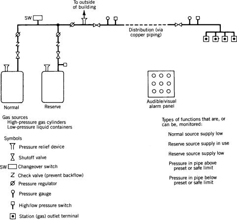
The following is a general description of components used in piped gas systems today (Fig. 1). An actual system may not utilize all these components. However, all systems have certain minimum safety features, as discussed below. In addition, standardization of some components (e.g., threaded station outlet connections) and practices (e.g., operating pressures) has evolved over the years, which will be discussed later as well.
GAS AND VACUUM SYSTEMS, CENTRALLY PIPED MEDICAL |
379 |
Gases. The most common nonflammable medical gases piped under pressure today include medical air, oxygen, nitrogen, and nitrous oxide. These gases are available from manufacturers in cylinders into which a large volume of the gas has been compressed. The pressure of the gas in these cylinders can be > 2000 psig (13.8 GPa). Some of these gases are also available in a liquefied state, through a refrigeration process, and are supplied in portable containers or in large stationary bulk units (tanks). (When the gas is used, it is allowed to evaporate and return to its gaseous state.) The gas in the liquefied state is placed under relatively low pressure [ 75 psig (520 kPa)]. One gas (air) can also be obtained on-site using compressors. Whichever method is used to obtain a specific gas, it must interface with the piping portion of the system; that is, the mechanical parts must interconnect. It also means that the pressure of the source gas needs to be regulated to pressure at which the system is operating. Gas in the liquid state must be transformed to the gaseous state. For all gases, except nitrogen, a pressure between 50 and 55 psig (344 and 379 kPa) at station outlets has become the standard. For nitrogen, which is used to power nonelectric surgical tools, such as drills, bone saws, and dermatomes, a pressure between 160 and 185 psig (1103 and 1379 kPa) is used. This regulation can be likened to electricity and the use of transformers that are installed between the power generators of utility companies (where voltages upward of 10,000 V are generated) and buildings where the voltage
Figure 1. Components of a medical gas (pressurized) central piping system (simplified). Standards have been developed for component and total-system performance and safety.
is regulated down to 208 or 110 V. In gas systems, these transformers are called pressure regulators.
In the last few years, other nonpatient medical gases (called support gases in NFPA 99, Standard for Health Care Facilities) have begun to be piped. These gases are used for powering equipment that use pressurized gas in order to function (e.g., pneumatically operated utility columns). Gases in this category include nitrogen and instrument air.
Source Equipment
Other devices used at the source portion of the piped gas system include (1) shutoff valves at prescribed locations so that a complete or partial shutdown of a source can be accomplished; (2) check valves to control the direction of gas flow (i.e., one direction only); (3) pressure-relief valves, which are preset to vent gas to the atmosphere if the pressure in a cylinder, container, or pipeline becomes excessive enough to cause a rupture or explosion if allowed to continue to increase; and (4) signals to alarm panels to indicate such conditions as low and high pressure.
A separate reserve supply of the gas is also included in some piped systems. This reserve serves as a backup if the main (normal) source is interrupted or requires repair. This reserve can be adjacent to, or remote from, the main source. Its remote location precludes both sources from damage should an accident occur to one source. Such separation, however, may not always be possible.
380 GAS AND VACUUM SYSTEMS, CENTRALLY PIPED MEDICAL
A requirement added in NFPA 99 in the early 1990s called for a piped bulk-oxygen system that has its source sources located outside the building to have a separate connection to the piping system, also located outside of the building and accessible to a bulk oxygen delivery truck (ODT). Thus, if both the main and reserve supplies of oxygen were to fail or become damaged or depleted, the ODT could be used as the source. This emergency connection is required only for the oxygen supply because it is a life-support gas.
Finally, if extra cylinders or containers of gases are kept stored within a facility or within close proximity to a healthcare facility, a safe means of storing the gas must be provided. These storage requirements are intended to provide safety for occupants should an incident occur outside the storage room (i.e., in order to protect the cylinders from adding to the incident), or should an incident occur inside the storage room (i.e., in order to protect occupants in the building from the incident in the storage room).
Piping (Distribution) System. From the source piping is installed to distribute the gas to patient care areas. (Standards require gases piped to laboratory areas to be supplied from a separate system from gases piped to patient care areas. This is to prevent any backfeeding of gas from laboratory systems into patient care systems, and to allow for different pressures where required or desired for laboratory purposes.) Sizes and locations of main, riser, and lateral pipes should take into consideration both present and future needs or plans. As with the source, shutoff valves and flow-control devices (check valves) are required by standards at certain locations in the piping (distribution) system.
Terminal Units (Station Outlets). The endpoints (called outlets) of the piped gas system are very important since it must be very clear what gas is flowing to each outlet. To eliminate any chance of mix-up, noninterchangeable mechanical connectors have been designed for each type of gas. These different connectors are similar to the different configurations of electrical outlets for 110, 220–208 (single-phase), 220–208 V (three-phase), and so on. Labeling of gas outlets and piping is also required. Color coding of new piping became a requirement in NFPA 99 in 2005. However, it requires staff to remember the color coding scheme. It also poses problems for persons who are colorblind.
Alarm Panels/Monitoring. Because gases are relied upon for life support, system monitoring is essential and has become standard practice. Sensors and alarms are required to be installed in all critical care areas to detect if the pressure decreases or increases beyond specified limits (e.g., should someone inadvertently or deliberately close a shutoff valve). Other sensors are required to detect when the normal source and/or reserve supply are low and when the reserve supply has been switched in.
All signals are fed to one or more master alarm panels, one of which is required to be constantly monitored by facility staff. The electrical power for these alarms is to
be connected to the facility’s emergency power system so that alarms will continue to function if normal electrical power is interrupted. This constant surveillance is required because of fire hazards that could develop should something in the system malfunction, and for patient safety should gas delivery be interrupted. Immediate action (corrective, responsive) is necessary in either situation.
Installation of Systems. In the early 1990s, concern about the quality of the installation of medical piped gas (and vacuum) systems resulted in the technical committee responsible for piping system requirements listed in NFPA 99, Standard for Health Care Facilities, to revise and expand requirements for their installation. To assure the system has been installed according to the design drawings, extensive requirements were included not only for the installer, but also for a verifier who is to be totally independent of the installer, and who tested the system after everything was connected and readied for operation (i.e., for patient use).
Performance Criteria and Standards
When first installed, medical piped gas systems generally followed the practices then in use for the piping of nonmedical gases. These practices were considered adequate at the time. In 1932, the subject came to the attention of the NFPA Committee on Gases, which noted the following hazards that the installation of these systems posed for hospitals:
1. Pipes, running through an extensive portion of a building into operating rooms, carried gases that were of the flammable type (those that burn or explode if ignited) or of the oxidizing type (those that support and intensify the burning of combustibles that have been ignited).
2. A large quantity of gas in cylinders was being concentrated and stored in one area.
3. The possible buildup of potentially hazardous gas concentrations existed should the pipes leak.
4. A possible explosion in an operating room was possible if a hose on an anesthesia machine were connected to the wrong gas.
5. A compromising of patient safety existed in that a mix-up of gases could be injurious or even fatal.
This notification came in the form of identification of hazards resulted in a request by the National Board of Fire Underwriters that this Committee develop a set of guidelines on the subject. The Committee studied the subject and, in 1933, proposed ‘‘Recommended Good Practice Requirements for the Construction and Installation of Piping Systems for the Distribution of Anesthetic Gases and Oxygen in Hospitals and Similar Occupancies, and for the Construction and Operation of Oxygen Chambers.’’ The proposed document contained guidance on acceptable types of piping, the length of pipe runs, the identification of piping, the kind of manifolds that were acceptable, and the number and location of shutoff valves. As noted
in the title, it permitted the distribution of anesthetic gases, which were flammable. The NFPA did not formally adopt the proposed Recommended Good Practice until 1934. Over the years, as more knowledge was gained from the hazards, installation, and use of piped gas systems, the NFPA standard also changed. In addition, other organizations prepared standards addressing other aspects of piped gas systems (1–10). A brief summary of these efforts follows.
National Fire Protection Association Standards. The original NFPA document, first designated NFPA 565 and later, NFPA 56F, which in turn was incorporated into NFPA 99 (11) remained unchanged until 1950 when the NFPA Hospital Operating Room Committee, working with the NFPA Gas Committee, recommended that piping of flammable anesthetic gases be prohibited. Later, specific safety requirements were added, such as for the storage of gases, shutoff valve locations, check valves, line-pressure gages, pressure switches and alarm panels, and installation and testing criteria. Performance criteria, in the form of operating pressure limits for different gases, were added because no other organization had included them in their documents, and uniformity of systems operations was helpful to both medical staff, designers, and the industry producing the equipment for these piped systems.
Other NFPA documents have been developed over the years that impact on medical piped gas systems. These include documents on the subjects of emergency electric power, bulk oxygen supplies, and building construction (11–16).
Compressed Gas Association (CGA) Standards. The CGA, an organization of manufacturers of gases and gas equipment, publishes many documents on the subject of gases. Some of these apply directly to medical gas piping systems; others are generic and affect any closed gas system. Topics addressed include gas cylinder criteria; noninterchangeable connectors for cylinders and terminal outlets; liquefied gas transfer connections; compressed gas-transfer connections; and commodity specifications for nitrogen, air, nitrous oxide, and oxygen (1–6).
GAS AND VACUUM SYSTEMS, CENTRALLY PIPED MEDICAL |
381 |
orifices and low vacuum levels if orifices became clogged or contaminated; and created excecssive loading on emergency electrical power systems if not properly provided for in the system). Since many vacuum systems were and still are installed simultaneously with central piping systems for gases, they added to the problems associated with installing two or more systems simultaneously (e.g., crossconnections, incorrect labeling).
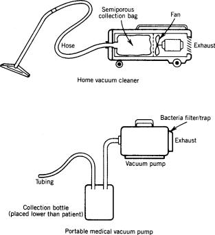
Until vacuum central piping systems were installed, medicine utilized small portable suction pumps that created a vacuum much the same way an ordinary vacuum cleaner creates suction (Fig. 2). A major difference, however, is the type of collection container used. For a home vacuum cleaner, a semiporous bag collects dirt; for a medical vacuum machine, a nonporous ‘‘trap’’ is necessary because of the products collected (e.g., body fluids of all kinds, semiliquid bulk material). In addition, a major problem with portable suction machines is the airborne bacteria it can spread as it operates. Since vacuum pumps operate on the principle of moving air from one place to another, this movement can be unhealthy in a healthcare setting where airborne bacteria can be infectious. Another problem with individual suction pumps was their need to be safe when flammable anesthetics were in use. (This ceased to be a problem as flammable anesthetics were replaced by nonflammable anesthetics in the 1960s and 1970s.) A central vacuum system eliminated these two problems, since it exhausted contaminated air outdoors and no electric motor was needed in the patient area in order to provide the vacuum. (It should not be concluded that portable suction pumps are no longer used. With bacteria filters now available and used on suction pumps,
Other Organizations. (7–10).
VACUUM SYSTEMS
Some History
The development of vacuum central piped vacuum systems, in place of portable suction machines, occurred over a period of time from the late-1940s to the early-1950s. These systems did not have to face the same unknowns and problems that the development of piped gases faced 20 years earlier. While they did not pose as great a threat as piped gases [i.e., they were not carrying oxidizing gases at 50 psig (344.8 kPa)], they did have their own hazards (e.g., they carried flammable and/or nonflammable oxidizing gases around a facility; created patient risks should the system stop; created possible restrictive contamination of
Figure 2. Home vacuum cleaner (high volume, low degree of vacuum) versus portable medical vacuum pump [low volume, low-to-high (adjustable) level of vacuum].
382 GAS AND VACUUM SYSTEMS, CENTRALLY PIPED MEDICAL
these devices are still quite suitable, in the same fashion that individual gas cylinders are still used.) It is necessary, however, that a trap unit be used between the patient and the vacuum control regulator and station inlet, so that nothing but air is drawn into the piping system.
The other reason central (add) vacuum systems began to be installed was the result of studies by the late David A. McWhinnie, Jr., in the early 1950s that showed the economic viability of these systems. Initially, vacuum central piped vacuum systems served only operating rooms and specialty areas, such as postanesthesia recovery rooms and emergency rooms. General patient care areas were added as demand for suction increased and economics made their installation viable. The reduction in the spread of airborne bacteria that central piped vacuum systems provided also contributed to their installation in general patient care areas as hospitals become more aware and concerned about this hazard. Pediatric and neonatal areas were last to install piped vacuum systems because of concern over what high degrees of vacuum and flow rates might do to babies (e.g., damage to very delicate tissues, possible collapse of newly functioning lungs). With improvements in the regulation of the degree of vacuum and more staff education, this concern abated, and piped vacuum systems were installed in these areas as well.
System Components
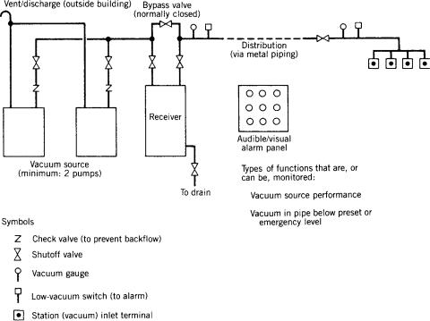
A medical piped vacuum system can be diagrammed, as shown in Fig. 3, in a fashion similar to the piped gas system described above. However, remember that the flow of subatmospheric air is opposite to the flow of pressurized gases in centrally piped gas systems. Note that piped vacuum systems require much larger orifices at
inlet terminals than those at outlet terminals for gas systems because of (1) the pressures involved [i.e., 12 in. (30.5 cm) of Hg (40.6 kPa) (negative pressure) as opposed to 50 psi (344.8 kPa)]; and (2) the need for high flow. As noted previously for piped gas systems, the following description for piped vacuum systems includes the major components of a large system. Of course, individual systems will vary.
Sources for Vacuum. Pumps provide the means by which suction is created. They draw in the air that exists within the piped system, and exhaust it via a vent discharge located on the outside of the building (generally on a roof) and away from any intake vents. This configuration allows exhausted air, which may be infectious, to dissipate into the atmosphere.
At least two pumps are required to be installed, each with either one capable of providing adequate vacuum to the entire system. This redundancy is necessary to keep the vacuum system functioning in case one pump fails or needs maintenance. To smooth out pump impulses and provide a constant vacuum, a receiver (surge tank) is required to be installed at the source site between the pumps and the rest of the system. Shutoff valves and check valves are to be installed for maintenance, and efficiency, and to shut down the system (or portions of the system) in the event of an emergency.
Piping (Distribution) System. Like piped gas systems, the first standard on piped vacuum systems required metal pipes to be used to connect the various patient care areas to the receiver. And like gas systems, there were and still are prescribed locations for shutoff valves, check valves, vacuum switches, and vacuum-level gages.
Figure 3. Components of a medical piped vacuum central piping system (simplified). Standards have been developed for component and totalsystem performance and safety. A collection unit and a trap are required between the inlet terminal and the patient.
However, because of the subatmospheric operating pressures and lower concentration of oxidizing gases in a piped vacuum system as opposed to a piped gas system, more types of metal pipes are allowed in the first standard on these vacuum systems. Piping for vacuum systems may have to be larger than piping for gas systems because of the level of airflow (vacuum) required by medical staff. Also, originally, the melting point allowed for joints can be lower for piped vacuum systems was permitted to be lower than the 10008 withstand-temperature required for piped gas systems. However, it is recognized that vacuum systems are sometimes installed at the same time as gas systems; as such, it may be prudent in those situations to use one type of piping throughout in order to reduce the chance of using the wrong piping and/or brazing on the piped gas system. In recent years, the committee responsible for piped vacuum system requirements has gradually required the type of piping for vacuum systems to be closer to that required for piped gas systems.
A significant difference of piped vacuum systems from piped gas systems permits connection of medical laboratories into patient care vacuum systems, though with the stipulation that the connection be made directly into the receiver and not via the pipes serving patient areas, so that a fluid trap and manual shut off valve are included. Separate systems, however, are encouraged.
Terminal Units (Station Inlets). The terminals for vacuum systems (called inlets), resemble the outlets of gas systems. Thus, it is required that they be clearly labeled vacuum or suction. To preclude problems (since piped vacuum systems sometimes are installed along at the same time with piped gas systems), the connector used for vacuum inlets is to be mechanically different from all gas outlet connectors, thereby reducing the chance of interconnection of gas and vacuum equipment.
Alarm Panels/Monitoring. Because vacuum is now a critical tool in the practice of medicine, it, too, requires constant monitoring. An audible/visual alarm panel (integrated with one for a piped gas system if also installed) alerts staff to problems similar to those of gas systems (e.g., pump malfunction, a drop in vacuum below a prescribed level).
Performance Criteria and Standards
With no vacuum standards in existence, the first piped vacuum systems installed were based on prevailing engineering expertise. While vacuum systems may seem similar to gas systems (e.g., piping, the movement of gas, although in the opposite direction), the design criteria for them are very different technically. With a piped gas system, after the source gas has been connected, the whole system reaches and stabilizes at a narrow range of pressure. In a piped vacuum system, a pump is trying to evacuate a space and provide a degree of vacuum [measured in inches of Hg (negative) and in volume displacement (flow)] at each inlet. In the former, the gas itself within the system provides a positive pressure and flow; in the latter, a pump is required to create a subatmospheric pressure and flow.
GAS AND VACUUM SYSTEMS, CENTRALLY PIPED MEDICAL |
383 |
In the early 1950s, ineffective performance plagued many piped vacuum systems. Staff techniques, the lack of appropriate check valves, and widely divergent pump sizing contributed to the problems. One city known to have been investigating the problem was Detroit. During the 1950s, the city attempted to establish a municipal standard for the piped vacuum systems in city hospitals. Several of the major manufacturers of vacuum pumps became involved in the effort. Because general agreement could not be reached, the manufacturers suggested that industry try to develop a standard. This led to Compressed Gas Association (CGA) involvement, since many of its members were by the late 1950s supplying vacuum pumps and inlet connectors. In 1961, the CGA released a document (designated P-2.1) that included recommendations on pumps, warning systems, piping, installation, and labeling. It also included recommendations on pump sizing.
During the 1960s, staff practices were improved or standardized. This included the location of collection bottles (below patient level) and the use of regulator bypasses. This helped system performance as well. Because there continued to be differences of opinion in the engineering world regarding piped vacuum system design, the CGA approached the NFPA in the early-1970s about the NFPA developing a medical–surgical vacuum system standard. The NFPA agreed to the idea and a subcommittee of the then Committee on Hospitals was established. After tests of various pumps and suction-therapy equipment, and surveys of actual systems in hospitals, a recommended practice (designated NFPA 56K) was adopted by NFPA in 1980. After 3 years, it was revised and changed to a standard (being incorporated into NFPA 99, Standard for Health Care Facilities, at the same time) (11). The NFPA recommended practice (and then standard) generally contained the same topics as the CGA document. Other standards that impact piped vacuum systems have been developed. Most have already been mentioned or listed for piped gas systems and cover such subjects as cleaning and purging, pressure testing, and connection for emergency electrical power.
As noted, the initial criteria for installing vacuum central piped vacuum systems differed from piped gas systems. Of late, the major document on the subject (NFPA 99) has gradually revised piped vacuum system requirements, particularly on piping material, to that required for piped gas systems. But if they a piped vacuum system is are installed alongside a piped gas system at the same time the gas system is installed, the installation standards of the gas system should be considered to avoid possible degradation of the gas system, which requires more stringent standards.
Requirements on piped vacuum system design have also been deleted from the NFPA 99 document as it was seen to be outside the scope of the document (NFPA 99 is a minimum performance safety standard), as well as not changed in the document for > 20 years.
MAINTENANCE OF SYSTEMS
A separate note on maintenance is deemed warranted because of the inherent hazards posed by piped gas and