

- •VOLUME 3
- •CONTRIBUTOR LIST
- •PREFACE
- •LIST OF ARTICLES
- •ABBREVIATIONS AND ACRONYMS
- •CONVERSION FACTORS AND UNIT SYMBOLS
- •EDUCATION, COMPUTERS IN.
- •ELECTROANALGESIA, SYSTEMIC
- •ELECTROCARDIOGRAPHY, COMPUTERS IN
- •ELECTROCONVULSIVE THERAPHY
- •ELECTRODES.
- •ELECTROENCEPHALOGRAPHY
- •ELECTROGASTROGRAM
- •ELECTROMAGNETIC FLOWMETER.
- •ELECTROMYOGRAPHY
- •ELECTRON MICROSCOPY.
- •ELECTRONEUROGRAPHY
- •ELECTROPHORESIS
- •ELECTROPHYSIOLOGY
- •ELECTRORETINOGRAPHY
- •ELECTROSHOCK THERAPY.
- •ELECTROSTIMULATION OF SPINAL CORD.
- •ELECTROSURGICAL UNIT (ESU)
- •EMERGENCY MEDICAL CARE.
- •ENDOSCOPES
- •ENGINEERED TISSUE
- •ENVIRONMENTAL CONTROL
- •EQUIPMENT ACQUISITION
- •EQUIPMENT MAINTENANCE, BIOMEDICAL
- •ERGONOMICS.
- •ESOPHAGEAL MANOMETRY
- •EVENT-RELATED POTENTIALS.
- •EVOKED POTENTIALS
- •EXERCISE FITNESS, BIOMECHANICS OF.
- •EXERCISE, THERAPEUTIC.
- •EXERCISE STRESS TESTING
- •EYE MOVEMENT, MEASUREMENT TECHNIQUES FOR
- •FETAL MONITORING
- •FETAL SURGERY.
- •FEVER THERAPY.
- •FIBER OPTICS IN MEDICINE
- •FICK TECHNIQUE.
- •FITNESS TECHNOLOGY.
- •FIXATION OF ORTHOPEDIC PROSTHESES.
- •FLAME ATOMIC EMISSON SPECTROMETRY AND ATOMIC ABSORPTION SPECTROMETRY
- •FLAME PHOTOMETRY.
- •FLOWMETERS
- •FLOWMETERS, RESPIRATORY.
- •FLUORESCENCE MEASUREMENTS
- •FLUORESCENCE MICROSCOPY.
- •FLUORESCENCE SPECTROSCOPY.
- •FLUORIMETRY.
- •FRACTURE, ELECTRICAL TREATMENT OF.
- •FUNCTIONAL ELECTRICAL STIMULATION
- •GAMMA CAMERA.
- •GAMMA KNIFE
- •GAS AND VACUUM SYSTEMS, CENTRALLY PIPED MEDICAL
- •GAS EXCHANGE.
- •GASTROINTESTINAL HEMORRHAGE
- •GEL FILTRATION CHROMATOGRAPHY.
- •GLUCOSE SENSORS
- •HBO THERAPY.
- •HEARING IMPAIRMENT.
- •HEART RATE, FETAL, MONITORING OF.
- •HEART VALVE PROSTHESES
- •HEART VALVE PROSTHESES, IN VITRO FLOW DYNAMICS OF
- •HEART VALVES, PROSTHETIC
- •HEART VIBRATION.
- •HEART, ARTIFICIAL
- •HEART–LUNG MACHINES
- •HEAT AND COLD, THERAPEUTIC
- •HEAVY ION RADIOTHERAPY.
- •HEMODYNAMICS
- •HEMODYNAMIC MONITORING.
- •HIGH FREQUENCY VENTILATION
- •HIP JOINTS, ARTIFICIAL
- •HIP REPLACEMENT, TOTAL.
- •HOLTER MONITORING.
- •HOME HEALTH CARE DEVICES
- •HOSPITAL SAFETY PROGRAM.
- •HUMAN FACTORS IN MEDICAL DEVICES
- •HUMAN SPINE, BIOMECHANICS OF
Spectrofluorimeter. An optical device that is used to measure the amount of light that is emitted by fluorescent compounds.
BIBLIOGRAPHY
Cited References
1.Hof M, Hutterer R, Fidler V. Fluorescence Spectroscopy in Biology. New York: Springer; 2005.
2.Lakowicz JR. Principles of Fluorescence Spectroscopy. New York: Plenum; 1983.
3.Valeur B. Molecular Fluorescence: Principles and Applications. New York: Wiley-VCH; 2004.
4.Albani JR. Structure and Dynamics of Macromolecules: Absorption and Fluorescence Studies. New York: Elsevier; 2004.
5.Kohen E, Hirschberg JG, Santus R. Fluorescence Probes in Oncology. Imperial College Press; 2002.
6.Sadtler Standard Fluorescence Spectra. Philadelphia: Sadtler Research Laboratories;
7.Passwater RA. Guide to Fluorescence Literature. Vols. 1–3. New York: Plenum; 1967.
8.Kringsholm B, Thomsen JL, Henningsen K. Fluorescent Y-chromosomes in hairs and blood stains. Forensic Sci 1977;9:117.
9.Giambernardi TA, et al. Neutrophil collagenase (MMP-8) is expressed during early development in neural crest cells as well as in adult melanoma cells. Matrix Biol 2001;20:577–587.
10.Stenfors LE, Raisanen S. Quantification of bacteria in middle ear effusions. Acta Otolaryngol 1988;106:435–440.
11.Rodrigues UM, Kroll RG. Rapid and selective enumeration of bacteria in foods using a microcolony epifluorescence microscopy technique. J Appl Bacteriol 1988;64:65–78.
12.Rivera OJ, et al. Role of promyelocytic leukemia body in the dynamic interaction between the androgen receptor and steroid receptor coactivator-1 in living cells. Mol Endocrinol 2003;17:128–140.
13.Snickers YH, van Donkelaar CC. Determining diffusion coefficients in inhomogeneous tissues using fluorescence recovery after photobleaching. Biophys J 2005.
14.Bentley KL, Thompson L, Klebe RJ, Horowitz P. Florescence polarization: A general method for studing ligand interactions. Bio Techniques 1985;3:356–366.
15.Rizzo MA, Piston DW. Hight-contrast imaging of fluorescent protein FRET by fluorescence polarization microscopy. Biophys J 2005;88:14–16.
16.Peng XH, et al. Real-time detection of gene expression in cancer cells using molecular beacon imaging: New Strategies for cancer research. Cancer Res 2005;65: 1909–1917.
17.Shagin DA, et al. GFP-like proteins as ubiquitous metazoan superfamily: Evolution of functional features and structural complexity. Mol Biol Evol 2004;21:841–850.
18.Branchini BR, et al. An alternative mechanism of bioluminescence color determination in firefly luciferase. Biochemistry 2004;43:7255–7262.
See also COLORIMETRY; MICROSCOPY, FLUORESCENCE; ULTRAVIOLET RADIATION IN MEDICINE.
FLUORESCENCE MICROSCOPY. See MICROSCOPY,
FLUORESCENCE.
FLUORESCENCE SPECTROSCOPY. See
FLUORESCENCE MEASUREMENTS.
FLUORIMETRY. See FLUORESCENCE MEASUREMENTS.
FUNCTIONAL ELECTRICAL STIMULATION |
347 |
FRACTURE, ELECTRICAL TREATMENT OF. See
BONE UNUNITED FRACTURE AND SPINAL FUSION, ELECTRICAL
TREATMENT OF.
FUNCTIONAL ELECTRICAL STIMULATION
GANAPRIYA VENKATASUBRAMANIAN
RANU JUNG
JAMES D. SWEENEY
Arizona State University
Tempe, Arizona
INTRODUCTION
Functional electrical stimulation (FES) is a rehabilitative technique where low level electrical voltages and currents are applied to an individual in order to improve or restore function lost to injury or disease. In its broadest definition, FES includes electrical stimulation technologies that, for example, are aimed at restoration of a sense of hearing for the deaf, vision for the blind, or suppression of seizures in epilepsy or tremors for people with Parkinson’s disease. Most FES devices and systems are known then as ‘‘neuroprostheses’’ because through electrical stimulation they artificially modulate the excitability of neural tissue in order to restore function. While sometimes used synonymously with FES, the term functional neuromuscular stimulation (FNS) is most commonly used to describe only those FES technologies that are applied to the neuromuscular system in order to improve quality of life for people disabled by stroke, spinal cord injury, or other neurological conditions that result in impaired motor function (e.g., the abilities to move or breathe). Another technology closely related to FES is that of therapeutic electrical stimulation (TES), wherein electrical stimulation is applied to provide healing or recovery of tissues (e.g., muscle conditioning and strengthening, wound healing). As will be seen, some FES and FNS technologies concurrently provide or rely upon such therapeutic effects in order to successfully restore lost function. For illustrative purposes, much of this article is centered on FNS and related TES devices and technologies. For a wider exposure to additional FES approaches and neural prosthetic devices, the reader is referred to this article’s Reading List, which contains references to a number of general books, journal articles, and on-line resources.
An important consideration in most all FNS technologies is that significant neural tissue remains intact and functional below the level of injury or disease so that electrical stimulation can be applied effectively. Individuals exhibiting hemiplegia (i.e., paralysis on one side of the body) due to stroke, for example, will exhibit paralysis in an impaired limb due to loss of control from the central nervous system (CNS), not because the peripheral nervous system (PNS) innervation of skeletal muscles in the limb has been lost. Similarly, while spinal cord injury (SCI) destroys motor neurons at the level of injury either partially or completely, many motor neurons below the level of injury may be spared and remain intact. Therefore, in stroke or SCI the axons of these intact motor neurons can be artificially excited by introducing an appropriate
348 FUNCTIONAL ELECTRICAL STIMULATION
electrical field into the body using electrodes located on the skin surface, or implanted within the body. Artificial excitation of motor nerves by electrical excitation can generate action potentials (propagating excitation waves) along axons that, when they arrive at synaptic motor-endplate connections to skeletal muscle fibers, act to generate muscle force much as the intact nervous system would. Thus, lower extremity FNS systems often have the objective of restoring or improving mobility for stroke or SCI individuals. Upper extremity FNS systems often are designed to restore or augment reaching and grasping movements for SCI subjects. Both FNS and TES technologies are of course not a cure for stroke, spinal cord injury or diseases (e.g., cerebral palsy or multiple sclerosis where FNS also has been used). They are also not universally beneficial, and must be carefully matched by a clinician to an individual and their medical condition (1). On the other hand, as will be seen in the remainder of this article, FES and TES systems can provide greatly improved quality of life for many people who use them.
THEORY AND APPLICATION
In 1961, Liberson and co-workers proposed the usage of electrical stimulation in what was called functional electrotherapy to restore or augment movement capability that has been lost or compromised due to injury or disease (2). Specifically, Liberson’s group developed the first electrical stimulation system for correction of hemiplegic drop foot: a gait disability occurring in some stroke survivors (for an excellent review of the history of development of neural orthoses for the correction of drop foot see Ref. 3). Moe and Post subsequently coined the term functional electrical stimulation to describe such techniques (4).
Electrical stimulation devices and systems now have been developed to activate paralyzed muscles in human subjects for a variety of applications in both the research lab and the clinic. Both FES and FNS systems have seen their greatest use as a tool for long-term rehabilitation of persons with neurological disorders (e.g., spinal cord injury, head injury, stroke) (5–10). For example, implanted electrical stimulation devices have been developed that can restore hand-grasp function to people with tetraplegia (11). Stimulation devices that utilizepercutaneouselectrodes (thin wires that cross the skin) have been developed to provide individuals with thor- acic-level spinal cord injury with the ability to stand and step (12–14). Other devices that utilize electrodes placed on the surface of the skin can restore standing and locomotor function to individuals with spinal cord injury or other neuromuscular disorders (6,8,15,16). One system that uses surface electrodes (Parastep,SigmedicsInc.) isFDA approved for use by people with thoracic level spinal cord injury and has been used at several rehabilitation centers worldwide. These efforts have clearly demonstrated that neuromuscular stimulation can be effectively used to activate paralyzed muscles for performing motor activities of daily living.
The basis by which all neuromuscular stimulation systems function is artificial electrical activation of muscle force, usually through excitation of the nerve fibers that innervate the skeletal muscle(s) of interest.
Excitation, Recruitment, and Rate Modulation
The nerve fibers that innervate skeletal muscle fibers are myelinated in nature, which means that they are regularly along their lengths ensheathed within layers of Schwanncell derived myelin separating exposed axonal membrane at nodes of Ranvier. Myelination enables increased propagation velocities via saltatory conduction in such nerve fibers. The cell bodies of these alpha motor neurons lie within the ventral horn of the spinal cord. The efferent axons of these cells ( 9–20 mm in diameter) pass out from the spinal cord via the ventral roots and project then to muscle fibers within peripheral nerve trunks. When spared during damage or disease of the nervous system, alpha motor neurons and their axons usually form the substrate of electrical activation of skeletal muscle force in FNS applications. This may come as something of a surprise to the reader, in that skeletal muscle cells are themselves also excitable. Why then is indirect stimulation of the innervating nerve fiber generally the mechanism by which force is generated rather than direct stimulation of the muscle cells themselves? The reason is that large myelinated nerve fibers are usually excited at lower stimulus amplitudes (voltage or current) and with shorter stimulus pulse widths than are skeletal muscle cells (assuming similar spatial separations of electrodes to cells) (17). Electrical stimulation of myelinated nerves to threshold occurs when a critical extracellular potential distribution is created along or near the cell. At threshold, outward transmembrane currents are sufficient to depolarize the nerve cell membrane voltage to the level where an action potential is generated.
In normal physiology, there exist two natural control mechanisms to regulate the force a single muscle pro- duces—recruitment and rate coding. Motor units are recruited naturally according to the Size Principle (18,19). Small alpha motor neurons innervating slow motor units have a low synaptic threshold for activation, and therefore are recruited first. As more force is demanded by an activity, progressively larger alpha motor neurons that innervate fast motor units are recruited. The second method of natural force regulation is called rate coding. Within a given motor unit there is a range of firing frequencies. Alpha motor neurons innervating fast-twitch motor units have firing rates that are higher than those that innervate slow-twitch units (20,21). Within that range, the force generated by a motor unit increases with increasing firing frequency. If an action potential reaches a muscle fiber before it has completely relaxed from a previous impulse, then force summation occurs. Twitches generated by the slow motor units have a fusion frequency of 5–10 Hz and reach a tetanic state at 25–30 Hz. The fast motor units may achieve fusion at 80–100 Hz (21,22).
The contractile properties of the muscle are largely dependent on the composition of the skeletal muscle (i.e., the muscle fiber types). The composition of muscle fibers varies across species. The composition of muscle fibers in the hindlimbs of the rat are predominantly fast fibers (23) whereas, human skeletal muscle is composed of a heterogenous collection of muscle fiber types (24). This is also indicated in the differences in fusion frequencies observed
|
|
FUNCTIONAL ELECTRICAL STIMULATION |
349 |
|
Table 1. Skeletal Muscle Fiber Types and Their Characteristics |
|
|
||
|
|
|
|
|
|
|
Skeletal Muscle Fiber Types and Characteristics |
|
|
|
|
|
|
|
Fiber type |
Type I |
Type IIa |
Type IIb |
|
|
|
|
|
|
Other names |
Slow red |
Fast red |
Fast white |
|
|
Slow oxidative (SO) |
Fast oxidative (FOG) |
Fast glycolytic (FG) |
|
|
Slow (S) |
Fast resistant (FR) |
Fast fatigable (FF) |
|
Motor unit size |
Smallest |
Moderate |
Largest |
|
Firing order |
1 |
2 |
3 |
|
Stimulation threshold |
Lowest |
Moderate |
Highest |
|
Force production |
Lowest |
Moderate |
Highest |
|
Resistance to fatigue |
Highest |
Moderate |
Lowest |
|
Contraction time |
Slowest |
Fast |
Fastest |
|
Mitochondrial density |
High |
High |
Low |
|
Capillary density |
Highest |
Moderate |
Lowest |
|
|
|
|
|
|
in the two species. The fusion frequency for muscles in the human is 25 Hz (25) and those for the muscles in the rat are higher ( 75 Hz) (26). As summarized in Table 1, from various mammalian studies, skeletal muscle fibers have been grouped into many different types according to physiological, ultrastructural, and metabolic properties. Based on histochemical measurements of adenosinetriphosphatase (ATPase) reactivities, muscles were classified into type I, type IIA, and type IIB (27). A differentiation based on combination of physiological and metabolic properties categorized muscle fibers as SO-, FOG-, FG- (28). Based on twitch speed and fatigue resistance, muscle fiber types were identified as S, FR, and FF (29). There is also an intermediate type of fast muscle fiber in certain muscles denoted type IIAB or FI (Fast Intermediate resistance to fatigue). The different muscle fiber types vary in the amount of force generated, speed of contraction, and fatigability. The slow fiber types (SO, Type I, S) generate lower force, but for a prolonged duration. They are very fatigue resistant. The fast fiber types (FG, IIB, and FF) are on the other end of the spectrum with greater force generating capacity, but briefer intervals of time. Also, these fatigue very quickly compared to slow fibers. Therefore, there is a trade off between the ability to produce force quickly and powerfully or slowly and steadily. Though slow fibers are able to generate a steady force for long periods of time, their force output is less. Fast fibers on the other hand can generate quicker, greater forces, but they fatigue very fast. Some fibers are classified in between the two extremes of slow and fast and are termed intermediate fibers. These are fast fibers, but with fatigue resistant capability (FOG, IIA, FR, IIAB, FI). The properties of these intermediate fibers lie between those of slow fibers and fast fibers. The force generated by these fibers is less that those generated by fast fibers and greater than the force produced by slow fibers.
The heterogeneity of muscle fibers within the muscle is in part due to the hierarchy of motor unit recruitment order (the Size Principle, described above) (30) indicating the influence of motor neuron activity upon muscle fiber phenotypes. The fiber-type composition within a muscle can be altered by altering the excitation patterns delivered to the muscle (induced by various exercise regimes). The best documented effects of such transformations are those that
occur after chronic, low frequency stimulation (CLFS) of a predominantly fast muscle using implanted electrode systems. The fast skeletal muscles of a number of mammalian species have been shown to change to the slower phenotype in response to chronic electrical stimulation (31–39). The muscle phenotype can be manipulated to enhance fatigue resistance at the expense of contractile power and speed (40–45). Changes in metabolic activity, and muscle mass have been documented too (38,46). These transformations are also dose dependent. A continuous stimulation of rabbit fast muscle at 10 Hz completely transform the muscle fibers to the slow phenotype, but lower frequencies of stimulation produce an intermediate state of conversion. However, stimulation at 2.5 Hz for 12 weeks (47,48) or 10 months (49) results in a whole muscle consisting mainly of the fast phenotype.
CLFS has been shown to affect human muscle in a manner similar to that in animals (50–57). Electrical stimulation has shown to increase strength–force and build fatigue resistance in muscles in both healthy and SCI individuals (56,58–63). An increase in passive range of motion has also been observed (64). Electrical stimulation has been shown to prevent the shift and loss of fibers in patients with paralyzed muscles thereby increasing fatigue resistance (60,65–67). A well-defined progression of changes is observed, whereby the muscle changes first its metabolic and then its contractile properties to become slow muscle (68). This has been documented in different species and muscles suggesting that probably the effects observed are not species or muscle specific. Following transformation, the new slow fibers are indistinguishable from normal slow skeletal muscle fibers. Also, from time series studies (69) and single fiber biochemistry (70,71) it is clear that the changes that occur result from transformation at the level of the single fiber and not from fast-fiber degeneration with subsequent slow-fiber regeneration.
From the above sections, it is clear that skeletal muscle is very adaptive, and therefore provides an opportunity for conditioning and therapy after an injury. Electrical stimulation based exercise has gained much significance in toning and conditioning muscles. Even though electrical stimulation techniques are being used increasingly for rehabilitation and therapy, note that in general electrical stimulation systems generate activation patterns and
350 FUNCTIONAL ELECTRICAL STIMULATION
|
0.1 |
|
|
|
2.5mA |
|
|
|
|
|
|
|
|
(Nm/kg) |
0.08 |
|
|
|
|
2.1mA |
|
|
|
|
|
||
|
|
|
|
|
|
|
Torque |
0.06 |
|
|
|
|
1.7mA |
0.04 |
|
|
|
1.3 mA |
||
|
|
|
|
|||
|
|
|
|
|
||
|
0.02 |
|
|
|
0.85mA |
|
|
|
|
|
|
||
|
0 |
|
|
|
|
|
|
0 |
100 |
200 |
300 |
400 |
500 |
|
|
|
PW |
(µs) |
|
|
(a)
Torque (Nm/kg)
0.1 |
|
|
|
|
500µs |
0.08 |
|
|
|
|
300µs |
0.06 |
|
|
|
|
|
0.04 |
|
|
|
|
100µs |
|
|
|
|
|
|
0.02 |
|
|
|
|
70µs |
|
|
|
|
40µs |
|
|
|
|
|
|
|
0 |
|
|
|
|
20µs |
0 |
0.5 |
1 |
1.5 |
2 |
2.5 |
Current (mA)
(b)
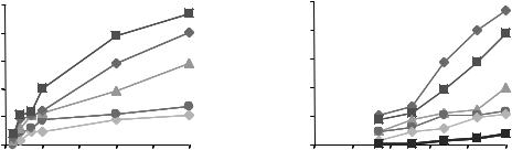
Figure 1. Typical force recruitment curves obtained from the ankle dorsiflexor muscle (Tibialis anterialis) of a rat through intramuscular stimulation. The recruitment curves indicate two techniques of force–torque modulation (a) pulse width modulation (PWM) and (b) pulse amplitude modulation (PAM). Single, symmetric, charge balanced, biphasic (cathodic first) pulses at an interval of 60 s were delivered. The currents were chosen as multiples of the twitch threshold current at 40ms.
recruitment characteristics quite different from the normal physiological mechanisms. With electrical stimulation, physiological muscle force regulation is controlled either by spatial summation or by temporal summation (72). Spatial summation (or electrical recruitment) is achieved by increasing the pulse width (Fig. 1a) and/or the pulse amplitude (Fig. 1b) of the electrical stimulus— extending the excitatory extracellular potential distribution further out from the stimulating electrode(s) to greater numbers of nerve fibers, and/or longer in time. Force recruitment curves are in general quite nonlinear. The isometric recruitment curve (IRC) of a muscle can be defined as the static gain relation between stimulus level and output force/torque when the muscle is held at a fixed length. The features of a typical IRC are an initial deadzone region, a high slope, monotonically increasing region, and a saturation region (73,74). These features can be explained by recognizing that the slope of the IRC is primarily a function of the electrode–nerve interface. The shape is dictated by the location and size distributions of the individual motor unit axons within the nerve with large diameter axons having a lower stimulus activation threshold than small diameter axons. The IRC depends on the past history of muscle activation and location of the electrode relative to the motor point. The motor point functionally is defined as the location (on the skin surface, or for implanted electrodes on the muscle overlying its innervation) where stimulation thresholds are lowest for the desired motor response. There is a drop in the maximum magnitude and slope of the monotonic region of the IRC on muscle fatigue (73,75). The IRC is also influenced by the muscle length tension curve (76) and, if muscle force is estimated by measuring joint torque, by the muscle nonlinear moment arm as it crosses the joint. Because of these factors, the IRC shape will be different for each muscle and set of experimental configurations and will also vary between subjects.
Temporal summation (also called rate modulation) varies the stimulus frequency or the rate of action potential firing on the nerve fiber(s). When electrodes are located
closer to the motor point for stimulation, enhanced spatial selectivity can be achieved because the electric field introduced can be focused closer to the a motor neuron fibers of interest. Another aspect of recruitment selectivity is fiber diameter, which relates to the tendency to stimulate subpopulations of nerve fibers based on their size. In electrical stimulation of myelinated fibers, there will be a tendency to recruit large axons at small stimulus magnitudes and then smaller axons with increased stimulus levels unlike during normal physiological recruitment—this is often dubbed reverse recruitment (77–79). Such reversed recruitment of motor units will inappropriately utilize fast, more readily fatigued muscle fibers for low force tasks. Slower fatigue resistant muscle fibers will only be recruited at higher stimulus levels. This also results in an undesirable steep relation between force output and stimulus magnitude. After injuries causing paralysis and disuse of muscle, many fatigue resistant muscle fibers tend to shift their metabolism toward less oxidative and more anaerobic, more readily fatigued mechanisms. Electrical stimulation therapy in such instances will recruit the faster muscle fibers first thereby inducing fatigue at a very early stage in the therapy.
FES DEVICES AND SYSTEMS
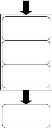
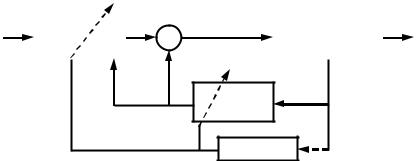
As illustrated in Fig. 2, all modern FES and FNS devices and systems incorporate (1) surface or implanted electrodes to generate an excitatory electric field within the body, (2) a regulated-current or regulated-voltage output stage that delivers stimulus pulses to the electrodes, (3) the stimulator pulse conditioning circuitry that creates the desired pulse shape, amplitude, timing, and pulse delivery (often within trains of pulses at set frequencies and for intended intervals), and (4) an openor closed-loop stimulator controller unit. Systems may be completely or partially implanted and often incorporate a microcontroller or computer interface. Smith and colleagues at the Cleveland FES Center, for example, have developed an externally
Control input(s)
Controller
Pulse |
Stimulator |
|
conditioning |
||
|
Output stage
Stimulus pulse(s)
Electrodes
Figure 2. The FES systems typically incorporate control signals from the user that a Controller stage acts upon. Patterns of stimulation pulses are shaped with a pulse conditioning module that in turn feeds pulse information to an output stage that delivers regulated-current or regulated-voltage pulses of the desired amplitudes and timing to one or more channels of electrodes which are in contact with, or implanted within, the body.
powered, multichannel, implanted stimulator with telemetry for control of grasp and release functions in individuals with cervical level (C5 and C6) spinal cord injuries (80). Wu et al. designed a PC-based LabView controlled multichannel FES system with regulated-current or regulated-voltage arbitrary stimulation waveform pattern capability (81).
Commercialized FES systems include, for example, the Bioness, Inc. H200/Handmaster. This U.S. Food and Drug Administration (FDA) approved device incorporates microprocessor controlled surface stimulation into a portable, noninvasive hand–wrist orthosis for poststroke rehabilitation [see, e.g., (82)]. The FreeHand System, commercialized by NeuroControl Corporation in Cleveland, implements implanted receiver-stimulator, external controller, electrode, and sensor technologies (Fig. 3) developed through the Cleveland FES Center into a system for restoration of control of hand grasp and release for C5/C6 level spinal cord injured individuals. Compex Motion (Fig. 4), a programmable transcutaneous electrical stimulation product of Compex SA, is designed as a multipurpose FES system for incorporation into rehabilitation therapies (83). The Parastep System developed by Sigmedics, Inc. is designed
FUNCTIONAL ELECTRICAL STIMULATION |
351 |
to enable independent, unbraced standing and walking for spinal cord injured people. Parastep is a noninvasive system that incorporates a battery-powered, microcomputer controlled stimulator unit (Fig. 5), surface electrodes, and a control and stability walker with finger activated control switches.
Electrode Designs for Electrical Stimulation
In the implementation of FES and FNS techniques, surface or implanted electrodes are used to create an excitatory electric field distribution within the targeted tissues. Researchers over the years have identified a number of important criteria for stimulation electrode selection and have developed a variety of electrode designs in order to meet specific application requirements (for an excellent recent review see Ref. 84).
Criteria for Electrode Selection. A few of the important factors identified for long-term applications are anatomical and surgical factors, mechanical and electrochemical characteristics, biocompatibility, long-term stability, and economics. Anatomical and surgical factors include ease of identification of stimulation site, either on the skin surface or through implantation. In the event of damage to the electrode, any implanted region should be easily accessible for retrieval and replacement. The mechanical properties of electrodes are important particularly with respect to implants whose lifetime is measured in years. Electrodes that are flexible, and consequently smaller in diameter, induce less trauma to muscles during movement. Instead of straight wires, coiled electrode wires provide for greater tension, and reduce the stress. The use of multistranded wires reduces breakage or provides redundancy if some wires should fail.
The electrical stability of the electrode is usually judged based upon reproducibility of muscle force recruitment curves. These depict some stimulation parameter (e.g., pulse width or current) against muscle force or torque output. As we have seen, the normal order of recruitment is generally reversed (larger motor units are activated before smaller ones). The threshold and the steepness of the curve are important properties that vary with electrode design, fiber size, and strength duration relations.
Another important criterion of consideration for choice of electrodes that are chronically implanted and tested over time is biocompatibility. The charge carriers in the electrode material (metal) are electrons unlike in our body wherein the charge carriers are ions. This results in a change of charge carriers when currents cross the metal–body interface. A capacitive double layer of charge arises at the metal–electrolyte interface; the single layer in the metal arises because of its connection to the battery, whereas that in the electrolyte is due to the attraction of ions in the electric field (85,86). These layers are separated by the molecular dimensions of the water molecule so the effective capacitance (being inversely proportional to charge separation) is quite high. At sufficiently low levels, the current will be primarily capacitive. But for high currents that exceed the capabilities of the capacitance channel, irreversible chemical reactions will take place

352 FUNCTIONAL ELECTRICAL STIMULATION
Figure 3. (a) Diagram of components for the implanted stimulation system developed at the Cleveland FES Center and commercialized as the Freehand neuroprosthesis by NeuroControl Corp. In the hand-grasp example shown, shoulder position is transduced for use as the command input. (b) The external control unit (ECU) provides the transducer interface, user control algorithm, multichannel stimulus coordination, and power for the implanted receiver-stimulator system. (c) The implanted receiverstimulator provides multiple channels of stimulus output via the leads seen in thefigure.Italsotransmitsimplantable sensor data to the ECU, and is powered through an inductive link that forms a coreless bidirectional transformer. Intramuscular or epimysial electrodes implanted in the forearm or hand are attached to the stimulator leads (not shown). (Courtesy of the Cleveland FES Center.)
that are undesirable since they are detrimental to the tissue or electrode or both. Therefore, the electrode material must have little impact on the electrochemistry at the electrode–tissue interface. For biocompatibility and to avoid local tissue damage induced by high current levels, the electrode materials used are essentially inert (e.g., platinum, platinum–iridium, and 316LVM stainless steel).
The above mentioned criteria for electrode selection are a general guideline for either skin surface or chronically implanted electrode systems. However, the choice of electrode is also application dependent. For example, during stimulation of the brain, of particular concern is prevention of breakdown of the blood–brain barrier. For nerve stimulation circular (82) electrodes can be placed within an insulating cuff; consequently, smaller amounts of current are required because the field is greatly confined. Also, lower current tends to minimize unwanted excitation of surrounding tissue. Finally, intramuscular electrodes, because of the implant flexing that must be withstood, are usually of the coiled-wire variety discussed above.
Electrode Classification. In general, electrodes designed to deliver electrical pulses to excitable tissue are classified based on the site of stimulation or placement of electrodes. Motor nerves can be stimulated through electrodes
placed on the surface of the skin (surface electrodes) or implanted within the body. Implanted electrodes include those placed on or in the muscle (epimysial or intramuscular electrodes, respectively); as well as within or adjacent to a motor nerve (intraneural or extraneural electrodes). Electrodes that stimulate the spinal cord and BIONs (electrodes integrated with sensing and processing and packaged into a capsule) are recent additions to the family of implanted electrode technologies. The above classification of electrodes is further described below and summarized in Table 2.
Surface Electrodes. Surface electrodes as the name implies are placed on the surface of the skin and are the earliest of the electrodes to be used for applications in electrotherapy. These consist of conductive plates and are available in many types including conductive rubber patches coated with electrolyte gel, metal plates contacting the skin via thin, moist sponges and flexible, disposable, stainless steel mesh or rubber electrodes with self-adhesive conductive polymers (98–100). They do not need any implantation and are therefore noninvasive and relatively easy to apply and replace. An excellent description on the placements of these electrodes can be found in the Rancho Los Amigos Medical Center’s practical guide to neuromuscular electrical stimulation (101). Surface electrodes
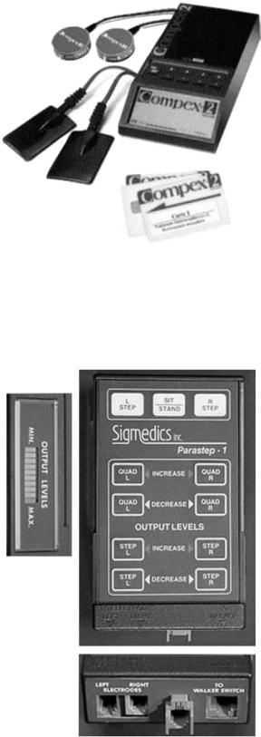
Figure 4. The Compex Motion FES system, manufactured by the Swiss based company Compex SA, is a general purpose programmable transcutaneous electrical stimulation device. Seen are the stimulator unit, three memory chip-cards that are inserted into the stimulator and used to store all pertinent information for a specific protocol, two EMG sensors, and two surface electrodes. (Reprinted from Ref. 83 with permission from the Institute of Physics and Engineering in Medicine.)
Figure 5. The neuromuscular stimulation unit for the Parastep system manufactured by Sigmedics, Inc. is battery-powered and microcomputer controlled. Cables connect the unit to surface electrodes, as well as to finger activated control switches on a walker. (Courtesy of Sigmedics, Inc.)
FUNCTIONAL ELECTRICAL STIMULATION |
353 |
do have some disadvantages. They offer relatively poor selectivity for stimulation, have elevated threshold levels, may activate skin pain receptors, and do not have highly reproducible positioning capability. When higher currents are delivered to stimulate deeper muscles, spill over of charge to the nontargeted superficial muscles occurs. It is sometimes difficult to anchor surface electrodes in moving limbs and electrical properties at the skin–electrode interface can be variable.
Surface electrodes have been used for both lower limb and upper limb motor prosthesis, including the aforementioned Parastep system for ambulation (Fig. 6). WalkAid was designed for the management of foot drop to help toe clearance during the swing phase of walking (102). A single channel stimulator, the Odstock Dropped Foot Stimulator (ODFS) and later a two channel stimulator (O2CHS) designed for foot drop correction, used self-adhesive skin surface electrodes placed on the side of the leg (103,104). MikroFES was another orthotic stimulator for correction of foot drop in paralyzed patients (9). The Hybrid Assist System (HAS) (105) and the RGO system (106) use surface stimulation along with braces. Upper extremity applications include the Handmaster (107), the Belgrade Grasp System (BGS) (108), and the Bionic Glove (109) which focus on improving hand grasp.
Implanted Electrodes. Implanted electrodes can either be in direct contact with a muscle or peripheral nerve, within a muscle and only separated by muscle tissue from the motor nerves innervating the muscles, or within the spinal cord. Since peripheral electrodes are closer to the motor nerves than surface electrodes, they allow for better selectivity and more repeatable excitation. Their positioning and implantation is more permanent. Implanted electrodes have the advantage of place and forget by comparison to surface electrodes. That is, once the system is implanted, the user potentially can forget it is there. The chances of spill over are reduced since the electrodes can be placed close to the target muscle or nerve. The sensation to the user is usually much more comfortable as the implantation is away from the cutaneous pain receptors and the threshold current amplitude is lower. However, the implant procedure is invasive and in case of implant failure an invasive revision procedure can be required. Improper design and implantation can lead to tissue damage and infection. Insufficient tensile strength, high threshold levels, highly nonlinear recruitment curves, poor selectivity of activation and repeatability and adverse pain sensation (110–112) indicate failure. Excess encapsulation and infection (113); mechanical failures of electrode lead breakage and corrosion of electrodes and the insulator (114,115) can also impair the system.
Electrodes in or on the Muscle: Intramuscular and Epimysial Electrodes. Implanted electrodes that are placed on or in the muscle consist of intramuscular (87,88,116–121) and epimysial electrodes (89,122–125). Intramuscular electrodes (88,126) can, for example, be fabricated from multistranded Teflon coated stainless steel wires. This configuration provides good tensile strength and flexibility. They are implanted by injecting a hypodermic needle

354 |
FUNCTIONAL ELECTRICAL STIMULATION |
|
|
|
Table 2. Electrical Stimulation Electrode Classifications and Types |
|
|
||
|
|
|
|
|
Location/Type |
Features and Advantages |
Example |
References |
|
|
|
|
|
|
Surface |
Metal plate with electrolyte gel, noninvasive |
WalkAid, ODFS, MikroFES, HAS, RGO, |
|
|
|
|
|
Handmaster, BGS, Bionic Glove |
|
In/On Muscle |
lower thresholds and better selectivity compared |
|
|
|
|
|
to surface electrodes |
|
|
Intramuscular |
Implanted in the muscle, multistranded Teflon |
|
87,88 |
|
|
|
coated stainless steel wire, monopolar and |
|
|
|
|
bipolar configurations, good tensile strength, |
|
|
|
|
and flexibility |
|
|
|
Epimysial |
Implanted under the skin: on the muscle, |
|
89 |
|
|
monopolar and bipolar configurations, less |
|
|
|
|
prone to mechanical failure |
|
|
|
BIONs |
Injected into or near the muscle, hermetically |
|
90 |
|
|
sealed glass/ceramic capsule integrated with |
|
|
|
|
electronics |
|
|
Near/On Nerve |
Lower threshold levels and better selectivity |
|
|
|
|
|
than the above mentioned electrodes |
|
|
Nerve Cuffs |
Monopolar, bipolar and tripolar configurations, |
|
91,92 |
|
|
|
good power efficiency, improved selectivity, |
|
|
|
|
comparatively stable |
|
|
|
FINE |
Reshape or maintain nerve geometry |
|
93 |
Intrafascicular |
Penetrate the epineurium and into the fascicle, |
|
|
|
|
|
selective stimulation, lower current and |
|
|
|
|
charge levels |
|
|
|
LIFE |
Stable, suitable for stimulating and recording |
|
94 |
|
SPINE |
Reduced nerve damage |
|
95 |
Intraspinal |
|
|
|
|
Microwires |
Near to normal recruitment, reduced fatigue, |
|
96,97 |
|
|
|
highly selective stimulation |
|
|
|
|
|
|
|
Figure 6. Examples of self-adhesive, reusable surface electrodes. The electrodes shown are used in the Parastep neuromuscular stimulation system. (Courtesy of Sigmedics, Inc.)
either nonsurgically or through an open incision. A fine needle probe used by itself or in conjunction with a surface probe is used to detect the motor point; the motor point for an intramuscular electrode is usually just below the muscle surface beneath the motor point position as defined by surface electrode. These electrodes can elicit a maximal muscular contraction with only 10% of the stimulus charge required by equivalent surface electrodes (25). Figure 7 depicts a Peterson type intramuscular electrode developed at Case Western Reserve University (121).
Both monopolar and bipolar intramuscular electrodes have been used. Bipolar intramuscular electrodes that
Figure 7. A ‘‘Peterson’’ type intramuscular electrode design. This is a helically wound PFS insulated multistranded 316LVM stainless steel wire design that is attached to a barb-like anchoring structure constructed of polypropylene suture material. The wound section of the electrode is 800mm in diameter and is partially loaded into a hypodermic needle. (Courtesy of J.T. Mortimer and reproduced by permission of World Scientific Publishing Co.)
straddle the nerve entry point can be as effective at activating the muscles as a nerve cuff. If bipolar electrodes do not straddle the nerve entry point, full recruitment of the muscle can require large stimulation charge and stimulation cannot be achieved without activating the surrounding muscles. In contrast, monopolar stimulation is less position dependent, though it cannot match the selectivity obtained with good bipolar placement (127). The size of the
muscle will determine the limit of electrode size, although large electrodes are more efficacious.
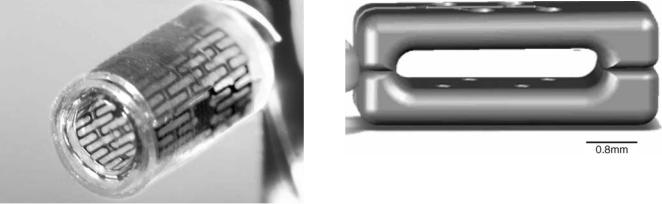
A recent development in the intramuscular stimulating electrode world are BIONs (for BIOnic Neurons), that can potentially provide precise and inexpensive interfaces between electronic controllers and muscles (90). The BIONs consist of a hermetically sealed glass–ceramic capsule with integral capacitor electrodes for safety and reliability (128). The internal electronics include an antenna coil wrapped around a sandwich of hemicylindrical ferrites over a ceramic microprinted circuit board carrying a custom integrated circuit chip. In animal studies, these electrodes have demonstrated long-term biocompatibility (129) and ability to achieve selective muscle stimulation (130). The first generation of BIONs, BION1, generates stimulation pulses of 0.2–30 mA at 4–512 ms duration. This system is now in clinical trials to provide therapeutic electrical stimulation to patients with disabilities (131–135). The second generation BION, BION2, is under development. BION2s are expected to sense muscle length, limb acceleration and bioelectrical potentials for feedback control in FES (136–138).
Intramuscular electrodes have been used to activate paralyzed muscles that retain a functional motor neuron in the muscles of the upper extremity (139,140), lower extremity (118,140,141) and the diaphragm (142). Muscles also have been stimulated to correct spinal deformities in the treatment of scoliosis (143).
Epimysial electrodes (89,110) are positioned on the surface of a muscle below the skin but not within the muscle. They have a smooth circular disk on one side and a flat, insulating backing, reinforced with mesh. The motor point is usually identified by moving a stimulating electrode across the muscle surface to locate the surface position that requires the least amplitude to fully excite the muscle. Replacing this electrode in the event of failure is comparatively easier. The stimulation levels and impedance are also similar to that of intramuscular electrodes. A perceived advantage of epimysial electrodes over intramuscular electrodes is that they are less prone to mechanical failure and less likely to move in the hours and days immediately after implantation.
Epimysial electrodes also can be used either in the monopolar mode or the bipolar mode (89,108,119,120,123). Use of a monopolar epimysial electrode close to the motor nerves results in reduced threshold stimulus amplitude, higher gain and selectivity, and decrease in length dependent recruitment. When a bipolar epimysial electrode is used, the stimulus current is constrained to regions closer to the two electrodes. Compared to the results with monopolar electrodes, the threshold is increased, relative gain decreased, and though greater selectivity is found with stimulation current levels close to twitch threshold poorer selectivity is present in the stimulus range needed for maximum activation of the muscle (108).
Epimysial electrodes have been used for a number of years in the implementation of upper extremity assist devices for C5 or C6 adult subjects with tetraplegia (Fig. 8), including incorporation into the FDA approved FreeHand System (144) and more recently for providing the capability of standing after paraplegia (117).
FUNCTIONAL ELECTRICAL STIMULATION |
355 |
Figure 8. An example implantable epimysial electrode (right) with intramuscular electrode (left), typical of those used with the Cleveland FES Center’s implanted hand-grasp system. (Courtesy of the Cleveland FES Center.)
Implanted Nerve Electrodes. Electrodes that are placed in contact with the nerve include extraneural and intraneural electrodes. Extraneural electrodes do not penetrate the epineurium and include varying designs of nerve cuffs (91,92,145–149) and the recently investigated flat interface nerve electrodes (FINE) (93,150,152). Intraneural electrodes penetrate the epineurium and include intrafascicular and interfascicular electrodes (94,95,153–157). Nerve electrodes have several potential advantages over intramuscular electrodes—including, lower power requirements, the ability to control several muscles with a single implant, and the ability to place the electrodes far from contracting muscles (158).
Electrodes placed on the surface of the nerve, and housed in an insulative carrier that encompasses the nerve trunk, are cuff electrodes (91,151,159,160). The cuff material is often silicone rubber and sometimes reinforced with Dacron. Cuff-type electrodes hold the stimulating contacts in close proximity to the nerve trunk. Holding the target tissues close to the stimulating contacts offers opportunities for power efficiency and improved selectivity. Less power is spent on electrical conduction through space between the electrode and target tissues. Improved selectivity is possible because the electric potential gradient is larger when the spacing between the stimulating contact and the target tissue is least. Further, these electrodes are less likely to move in relationship to the target tissues after implantation (161–164). However, while nerve cuffs stimulate effectively and selectively they require invasive surgery for implantation. They may also damage the nerves they enclose unless carefully designed, sized, and implanted.
356 FUNCTIONAL ELECTRICAL STIMULATION
Figure 9. A self-sizing cuff electrode design fabricated using PMP (polymer–metal–polymer) technology and laser machining. (Courtesy of J.T. Mortimer and M. Tarler.)
To overcome potential problems with a fixed cuff-size, nerve cuff electrodes have been designed with different configuration. The Huntington nerve cuff (165), is a helixtype nerve electrode system that has exposed metal sections as stimulating contacts along the internal diameter of the helix. The open helix design can accommodate some swelling. Other self-sizing cuff electrode designs sometimes have a spiral configuration that enables opening or closing to accommodate a range of different diameter nerves (91). Figure 9, for example, is a photo of a self-sizing nerve cuff fabricated at Case Western Reserve University using PMP technology and laser machining. Both cuff and spiral electrode configurations can be used in various monopolar, bipolar or tripolar configurations (91,164). Cuff electrodes with multiple electrical contacts can produce selective activation of two antagonistic muscle groups innervated by that nerve trunk (166). Increased function and additional control of muscles with minimum number of electrodes can be achieved. Self-sizing nerve-cuff electrodes, with multiple contacts in a tripolar configuration, have been shown to produce controlled and selective recruitment of some motor nerves in a nerve trunk (145,158,167– 170). A monopolar electrode with four radially placed contacts can work as well as a tripolar electrode with four radially placed tripoles (171,172). A four contact self-sizing spiral cuff electrode has been described as a tunable electrode that is capable of steering the excitation from an undesirable location to a preferred location (92).
The flat interface nerve electrode, or FINE system as seen in Fig. 10, has been introduced in an attempt to improve the stimulation selectivity of extraneural electrodes (151). The goal with the FINE is to create a geometry that optimizes stimulation selectivity. In contrast to cylindrical electrodes, the FINE either reshapes the nerve into, or maintains the nerve in, an ovoid geometry. Chronic studies in rats have demonstrated that nerves and fascicles can be safely reshaped (150,173). Also, acute experiments and finite element models have demonstrated that it is possible to selectively activate individual fascicles in the cat sciatic nerve using this electrode (151,152,174). This could be important in both reducing fatigue and selectively activating individual muscles (153,175). A potential disadvantage
Figure 10. The FINE nerve cuff design, intended to flatten peripheral nerve trunks into a layering of nerve fascicles. Electrode contacts are seen as small dots within the overall structure. (Courtesy of D. Durand.)
is that a fibrous capsule with electrical properties different from the surrounding tissues will envelope the electrode (176,177), potentially rendering the recruitment properties unstable, although a recent study has shown that both selectivity measurements and the recruitment curve characteristics can remain stable for a prolonged implant period (93).
Intraneural electrodes are positioned to penetrate the epineurium around the nerve trunks. Intraneural electrodes utilize a conductor that invades the epineurium. Maximal contraction is elicited at stimulation levels an order of magnitude lower than with nerve cuff electrodes (200 mA, pulse duration 300 ms). However, connectors, fixation, and neural damage are still not completely resolved to allow routine clinical usage. Intraneural multipolar sword type electrodes have been made out of solid silicon with golden contacts and can be very selective (178). Such electrodes could minimize the needs for using many electrodes for activation of different muscles that are innervated from a single nerve (179).
A subset of intraneural electrodes are meant to enter the perineurium around the fascicles and go between the nerve fibers: These are so-called intrafascicular electrodes. Intrafascicular electrodes place stimulating elements inside the fascicles, in close proximity to axons (126,153,160,175,178,180,181). They have been shown to produce axonal recruitment with almost no excitation of muscles that are not targeted (181). A variation of the intrafascicular electrode is the longitudinal intrafascicular electrode (LIFE) (94,153). Compared with extraneural electrodes, LIFEs have many advantages and can be implanted into any of the fascicles of peripheral nerves to selectively stimulate a single fascicle thereby offering highly selective stimulation. Also they serve as excellent recording electrodes. When LIFEs are used as recording electrodes, the amplitudes of motor evoked potentials (MEPs) recorded by LIFEs implanted in fascicles are much larger than those of EMGs recorded from the skin by surface electrodes and the signals recorded are not affected by external electrical fields (155,182). Therefore, the signals recorded by LIFE can be used to control a prosthetic limb more accurately than those controlled by EMGs (183). In addition, LIFEs have excellent biocompatibility with peripheral fascicles (156,184,185).
While intrafascicular electrodes can provide high degrees of selectivity, it remains unclear whether penetrating the perineurium will lead to long-term nerve injury (126,186). Interestingly, an intraneural electrode system dubbed the slowly penetrating interfascicular electrode (SPINE) has been developed, which has been reported to penetrate a peripheral nerve within 24 h without evidence of edema or damage of the perineurium and showed functional selectivity (95).
In general, compared to externally placed electrodes, the current and charge stimulation requirements for intraneural electrodes are low since they are positioned inside the nerve trunk to be excited. Also, the stimulation selectivity is high compared to extraneural electrodes where stimulation selectivity suffers from the relatively large amount of tissue interposed between the stimulating contacts and the target axons.
Micro wires: Electrodes for Intraspinal Stimulation
Spinal circuits that are shown to have the capacity of generating complex behaviors with coordinated muscle activity can be activated by intraspinal electrical stimulation (187–190). Microwires that are finer than a human hair have been used to stimulate the spinal cord neurons to control single muscles or small group of synergists (96,97,191–193). Stimulation through single wires in a few sites has been shown to have the ability to elicit whole-limb activation sufficient to support the animal’s weight (191,192,194–196). The stimuli were not perceived but were able to produce strong coordinated movements. Near normal recruitment order, minimal changes in kinematics and little fatigue and functional, synergistic movements induced by stimulation in the lumbosacral cord (97,194,196) are some of the promising advantages of stimulating the spinal cord with microwires. However, the clinical and long-term feasibility of implanting many fine microwires into the spinal cord remains questionable. In addition, stimulating the spinal cord results in steep recruitment curves compared to muscle and nerve stimulation thereby limiting the degree of control achievable.
Controllers and Control Strategies
Besides stimulating the paralyzed muscles, it is also important to control and regulate the artificial movements produced. The control task refers to specification of the temporal patterns of muscle stimulation to produce the desired movements; and the regulation task is the mod-
FUNCTIONAL ELECTRICAL STIMULATION |
357 |
ification of these patterns during use to correct for unanticipated changes (disturbances) in the stimulated muscles or in the environment. A major impediment to the development of satisfactory control systems for functional neuromuscular stimulation has been the nonlinear, time varying properties of electrically activated skeletal muscle that make control difficult to achieve (7,76,197). With FNS, the larger, fatigable muscle fibers are recruited at low levels of stimulation before the more fatigue-resistant fibers are activated thereby inducing rapid fatigue (56). It is important that the output of any FNS control system results in stable, repeatable, regulated muscle input– output properties over a wide range of conditions of muscle length, electrode movement, potentiation, and fatigue. To improve control strategies to provide near physiological control, inherent muscle characteristics (force-activation, force-length, and force-velocity), muscle modeling studies, studies on understanding how to model the patterns of neural prostheses and how neural prostheses respond to disturbances have been performed (197–200).
As depicted in Fig. 11 (201), FNS control methods include feedforward (open-loop), feedback, and adaptive control. Feedforward control requires a great deal of information about the biomechanical behavior of the limb. The control algorithms specify the stimulus parameters (musculoskeletal system inputs) that are expected to be needed to produce the desired movement (system outputs). In an open-loop control system these parameters are often identified by trial and error (6,13,202–205). The same stimulation pattern, which is often stored in the form of a lookup table, is delivered for each cycle of movement.
Three major problems exist with this form of fixedparameters, open-loop control (204–206). First, the process of specifying the parameters for a single stimulation pattern for a single user often requires several extensive sessions involving the user, therapist, physician, and engineer. This process is often expensive, time consuming, and often only minimally successful in achieving adequate performance. Second, the fixed parameter stimulation pattern may not be suitable after muscles fatigue that is exacerbated by the stimulation paradigm itself. The third problem is that the open-loop stimulation pattern does not respond to changing environments (e.g., slope of walking surface) and external perturbations (e.g., muscle spasms).
To address the limitations of open-loop control systems feedback control was implemented (12,14,207,208). In a feedback control system, sensors monitor the output and corrections are made if the output does not behave as
User |
Feedforward |
Stimulation |
Musculoskeletal |
System |
inputs |
controller |
|
system |
outputs |
|
|
|
|
|
Feedback controller
Adaptation
Figure 11. A representation of FNS control system components and strategies (feedforward, feedback and adaptive). (Reproduced by permission from Neuromodulation 2001;4: 187–195.)
358 FUNCTIONAL ELECTRICAL STIMULATION
desired. The corrections are made based on a control law, which is a mathematical prescription for how to change the input to reduce the difference (error) between the desired output and the actual output. Feedback control requires output sensors, and compensation is generally slower than in feedforward control since an output error must be present to generate a controller response. Thus feedback control might best be used for slow movements and for maintaining a steady posture. Since the output of the feedback controller is highly dependent on sensor signals, the quality of the control that is achieved will be compromised by the relatively low quality of sensors that are available. Feedback control has been successful in regulating hand grasp (209) and standing posture (12), but it appears that another strategy, adaptive feedforward control, is likely to be required for dynamic activities such as locomotion.
To improve performance of feedback control systems, adaptive control strategies were developed that automatically adjusted the overall system behavior (i.e., the combined response of the controller and the system) so that it is more linear, repeatable, and therefore predictable (75,210– 213). These techniques adjust the parameters of the control system and attempt to self-fit the system to the user in order to make it easier to use and learn to use (206,212,214). The control system developed by Abbas and Chizeck has a pattern generator (PG) and a pattern shaper (PS) (211,215). The PG generates the basic rhythm for controlling a given movement. The PS adaptively filters those signals and sends its output to the muscles. The adaptive properties of the PS provide the control system with the ability to customize stimulation parameters for a particular individual and to adjust them on-line to account for fatigue. In some of the computer simulation experiments a proportional-derivative feedback controller was also active. Studies have shown that the pattern generator/ pattern shaper (PG/PS) adaptive neural network controller is able to account for nonlinear and dynamic system properties and muscle fatigue (73,75,213). To summarize, adaptive control systems have replaced other developed control system strategies because this strategy can (1) provide the ability to automatically customize the stimulation pattern for a given user, (2) automatically adjust stimulation parameters to account for fatigue, and (3) automatically adjust to allow the voluntary motor commands to recover control of the movement pattern (in the case of partial recovery in a person with an incomplete spinal cord lesion).
Apart from the above other strategies, such as fuzzy logic (216) and proportional–integral–derivative (PID) controllers (217) have also been implemented to investigate automatic fatigue compensation. However, fatigue remains one of the major factors limiting utility of FES/FNS because such adaptive systems can adjust for fatigue only up to the contractile limits of the muscle.
Rather than initiating and modulating control of FES systems indirectly through residual motor function (e.g., as in the Freehand system for grasping, where paralyzed hand closure and opening were command controlled through sensing of opposite shoulder position), future FES devices might be controlled directly through thought—by tapping into the subject’s remaining cortical
intent to move via a brain–machine interface (BMI) [or sometimes brain–computer interface (BCI)]. So-called direct brain–machine interfaces utilize arrays of intracortical recording electrodes to sense action potentials from a host of individual neurons in regions of the brain where cells code for movement and its intent. A number of research teams have in recent years demonstrated the feasibility of recording and processing movement related signals from cortex (in both animals and in humans), and then enabling the subject to control computers or devices directly through such processed thought (218–220). Ultimately, BMI technologies hold promise that paralyzed individuals might one day be able to control FES devices for movement restoration with little or no effort or learning other than forming the simple intent to move (221).
THERAPEUTIC EFFECTS OF ELECTRICAL STIMULATION
While this article is focused mainly on electrical stimulation therapies for restoring lost function, it is important to recognize that electrical stimulation techniques are used also for therapeutic reasons. A recent review summarizes the current state of therapeutic and neuroprosthetic applications of electrical stimulation after spinal cord injury and identifies some future directions of research and clinical and commercial development (222). Functional electrical stimulation therapy individually and in combination with other rehabilitation therapies also is being utilized after incomplete spinal cord injury to influence the plasticity within the nervous system for improved recovery (9,223–228).
Therapeutic electric stimulation (TES) can affect the restoration of muscle strength (229). Therapeutic electric stimulation in humans has been shown to prevent muscle atrophy thereby increasing muscle cross-sectional area, torque, and force (230–234). Such electrical therapy has been effective in reversing the increased fatigability associated with the change in fiber type in both animals (31–37) and humans (56,59–61,65–67) after spinal cord injury. Electrical stimulation has also been able to reduce spasticity among patients with neurological disorders (reference).
While osteoporosis has been prevented in the limbs of paralyzed individuals, in menopausal women, and in the elderly and fracture patients through electrical stimulation therapy (235–240), certain other studies have shown little or no change in bone density (235,241–244). These contradictory results suggest the importance of other characteristics, such as the stimulation patterns, specifications for training (intensity, duration, loading), and the time postinjury. Enhancing fracture–wound healing is another therapeutic application of electrical stimulation (245–249). The theory here is to attract negatively or positively charged cells into the wound area, such as neutrophils, macrophages, epidermal cells, and fibroblasts that in turn will contribute to wound healing processes by way of their individual cellular activities (250). Electrical stimulation may also play a role in wound healing through improved blood flow (251,252), prevent occurrence of pressure sores thereby improving general tissue health (253). A recent
review details all the theories suggested and experimental studies and clinical trials performed on wound healing through electrical stimulation (254).
Recent applications of electrical stimulation have also been successful in altering neural function. For example, deep brain stimulation (DBS) is being used to treat a variety of disabling neurological symptoms, most commonly the debilitating symptoms of Parkinson’s disease (PD), such as tremor, rigidity, stiffness, slowed movement, and walking problems [for a review, see (255,256)]. Deep brain stimulation uses a surgically implanted, neurostimulator approximately the size of a stopwatch. The implanted device delivers electrical stimulation to targeted areas in the brain that control movement, blocking the abnormal nerve signals that cause tremor and PD symptoms. Vagal nerve stimulator (VNS), approved by the FDA in 1997 are used to treat patients with intractable epilepsy. These devices controls seizures by sending electrical pulses to the vagus nerve (257,258). Transcutaneous electrical nerve stimulation (TENS), wherein electrical signals are sent to underlying nerves, can relieve a wide range of chronic and acute pain (259). The TENS devices are small battery-powered stimulators that produce low intensity electrical signals through electrodes on or near a painful area, producing a tingling sensation that reduces pain. Chronic electrical stimulation of the GI tract has been found to be a potential therapy for the treatment of obesity (260–262). It is clear that in future development of electrical stimulation technologies many devices will be designed to achieve both therapeutic and functional outcomes.
ACKNOWLEDGMENT
This work was in part supported by NIH (NCMRR)–HD- 40335.
BIBLIOGRAPHY
Cited References
1.Kilgore KL, Kirsch RF. Upper and lower extremity motor neuroprostheses. In: Horch KW, Dhillon GS, editors. Neuroprosthetics: Theory and Practice, New Jersey: World Scientific; 2003. pp 844–877.
2.Liberson WT, Holmquest HJ, Scot D, Dow M. Functional electrotherapy: stimulation of the peroneal nerve synchronized with the swing phase of the gait of hemiplegic patients. Arch Phys Med Rehabil 1961;42:101–105.
3.Lyons GM, Sinkjaer T, Burridge JH, Wilcox DJ. A review of portable FES-based neural orthoses for the correction of drop foot. IEEE Trans Neural Syst Rehabil Eng 2002;10(4): 260–279.
4.Moe JH, Post HW. Functional electrical stimulation for ambulation in hemiplegia. J Lancet 1962;82:285–288.
5.Bajd T, Andrews BJ, Kralj A, Katakis J. Restoration of walking in patients with incomplete spinal cord injuries by use of surface electrical stimulation-preliminary results. Prosthet Orthot Int 1985;9(2):109–111.
6.Krajl A, Bajd T. Functional Electrical Stimulation: Standing and Walking After Spinal Cord Injury. Boca Raton (FL): CRC Press; 1989.
7.Yarkony GM, Roth EJ, Cybulski G, Jaeger RJ. Neuromuscular stimulation in spinal cord injury: I: Restoration of
FUNCTIONAL ELECTRICAL STIMULATION |
359 |
functional movement of the extremities. Arch Phys Med Rehabil 1992;73(1):78–86.
8.Stein RB, et al. Electrical systems for improving locomotion after incomplete spinal cord injury: an assessment. Arch Phys Med Rehabil 1993;74(9):954–959.
9.Bajd T, Kralj A, Stefancic M, Lavrac N. Use of functional electrical stimulation in the lower extremities of incomplete spinal cord injured patients. Artif Organs 1999;23(5):403– 409.
10.Stein RB. Functional electrical stimulation after spinal cord injury. J Neurotrauma 1999;16(8):713–717.
11.Peckham PH, Keith MW. Motor prostheses for restoration of upper extremity function., in Neural prostheses: Replacing motor function after disease or disability. New York: Oxford University Press; 1992. pp 162–190.
12.Chizeck HJ, et al. Control of functional neuromscular stimulation systems for standing and locomotion in paraplegics. Proc IEEE 1988;1155–1165.
13.Marsolais EB, Kobetic R. Development of a practical electrical stimulation system for restoring gait in the paralyzed patient. Clin Orthop 1988;233:64–74.
14.Abbas JJ, Chizeck HJ. Feedback control of coronal plane hip angle in paraplegic subjects using functional neuromuscular stimulation. IEEE Trans Biomed Eng 1991;38(7):687– 698.
15.Solomonow M. Biomechanics and physiology of a practical
functional neuromuscular stimulation walking orthosis for paraplegics. In: Stein RB, Popovic DP, editors. Neural Prostheses: Replacing motor function after disease or disability. New York: Oxford University Press; pp 202– 232.
16. Graupe D, Kohn KH. Functional electrical stimulation for ambulation by paraplegics, in Functional electrical stimulation for ambulation by paraplegics. Krieger; 1994.
p 194.
17.Mortimer JT. Motor Prostheses. In: Brookhart JM, Mountcastle VB, Brooks VB, Geiger SR, editors. Handbook of Physiology, Section 1: The Nervous System, Vol. II Motor Control, Part I. Bethesda (MD): American Physiological Society; 1981.
18.Henneman E, Somjen G, Carpenter DO. Functional Significance of Cell Size in Spinal Motoneurons. J Neurophysiol 1965;28:560–580.
19.Henneman E, Somjen G, Carpenter DO. Excitability and inhibitability of motoneurons of different sizes. J Neurophysiol 1965;28(3):599–620.
20.Burke RE. Firing patterns of gastrocnemius motor units in the decerebrate cat. J Physiol 1968;196(3):631–654.
21.Burke RE. Motor units: Anatomy, physiology and functional organization. In: Brooks VB, editor. Handbook of Physiology Section 1: The Nervous System. Vol. III. Motor Systems. Bethesda (MD): American Physiology Society; 1981. pp 345– 422.
22.McPhedran AM, Wuerker RB, Henneman E. Properties of Motor Units in a Heterogeneous Pale Muscle. J Neurophysiol 1965;28:85–99.
23.Armstrong RB, Phelps RO. Muscle Fiber Type Composition of the Rat Hindlimb. Am J Anat 1984;171:256–272.
24.Staron RS. Human skeletal muscle fiber types: delineation, development, and distribution. Can J Appl Physiol 1997; 22(4):307–327.
25.Popovic D, Sinkjaer T. Control of Movement for the Physically Disabled. London: Springer-Verlag; 2003.
26.Ichihara K, et al. Muscle stimulation in a rodent model: electrode design, implantation and assessment. 9th Annual Conference of the International FES Society. Bournemouth (UK): 2004.
360FUNCTIONAL ELECTRICAL STIMULATION
27.Brooke MH, Kaiser KK. Muscle fiber types:How many and what kind? Arch Neurol 1970;23:369–379.
28.Peter JB, et al. Metabolic profiles of three fiber types of skeletal muscle in guinea pigs and rabbits. Biochemistry 1972;11:2627–2633.
29.Burke RE, Levine DN, Tsairis P, Zajac FE. Physiological types of histochemical profiles in motor units of the cat gastrocnemius. J Physiol 1973;234:723–748.
30.Pette D, Staron RS. Cellular and molecular diversities of mammalian skeletal muscle fibers. Rev Physiol Biochem Pharmacol 1990;116:1–76.
31.Brown WE, Salmons S, Whalen RG. The sequential replacement of myosin subunit isoforms during muscle type transformation induced by long term electrical stimulation. J Biol Chem 1983;258(23):14686–14692.
32.Brownson C, et al. Changes in skeletal muscle gene transcription induced by chronic stimulation. Muscle Nerve 1988; 11(11):1183–1189.
33.Brownson C, Little P, Jarvis JC, Salmons S. Reciprocal changes in myosin isoform mRNAs of rabbit skeletal muscle in response to the initiation and cessation of chronic electrical stimulation. Muscle Nerve 1992;15(6): 694–700.
34.Carraro U. Contractile proteins of fatigue-resistant muscle. Semin Thorac Cardiovasc Surg 1991;3(2):111–115.
35.Kirschbaum BJ, Heilig A, Hartner KT, Pette D. Electrostimulation-induced fast-to-slow transitions of myosin light and heavy chains in rabbit fast-twitch muscle at the mRNA level. FEBS Lett 1989;243(2):123–126.
36.Pette D, Muller W, Leisner E, Vrbova G. Time dependent effects on contractile properties, fibre population, myosin light chains and enzymes of energy metabolism in intermittently and continuously stimulated fast twitch muscles of the rabbit. Pflugers Arch 1976;364(2):103–112.
37.Sreter FA, Gergely J, Salmons S, Romanul F. Synthesis by fast muscle of myosin light chains characteristic of slow muscle in response to long-term stimulation. Nat New Biol 1973;241(105): 17–19.
38.Pette D, et al. Partial fast-to-slow conversion of regenerating rat fast-twitch muscle by chronic low-frequency stimulation. J Muscle Res Cell Motil 2002;23(3):215–221.
39.Putman CT, et al. Fiber-type transitions and satellite cell activation in low-frequency-stimulated muscles of young and aging rats. J Gerontol A Biol Sci Med Sci 2001;56(12):B510– B519.
40.Jarvis JC. Power production and working capacity of rabbit tibialis anterior muscles after chronic electrical stimulation at 10 Hz. J Physiol 1993;470:157–169.
41.Mannion JD, et al. Histochemical and fatigue characteristics of conditioned canine latissimus dorsi muscle. Circ Res 1986;58(2):298–304.
42.Trumble DR, LaFramboise WA, Duan C, Magovern JA. Functional properties of conditioned skeletal muscle: implications for muscle-powered cardiac assist. Am J Physiol 1997;273(2 Pt. 1):C588–C597.
43.Salmons S, Vrbova G. The influence of activity on some contractile characteristics of mammalian fast and slow muscles. J Physiol 1969;201(3):535–549.
44.al-Amood WS, Buller AJ, Pope R. Long-term stimulation of cat fast-twitch skeletal muscle. Nature (London) 1973; 244(5413): 225–257.
45.Glatz JF, et al. Differences in metabolic response of dog and goat latissimus dorsi muscle to chronic stimulation. J Appl Physiol 1992;73(3):806–811.
46.Ferguson AS, et al. Muscle plasticity: comparison of a 30-Hz burst with 10-Hz continuous stimulation. J Appl Physiol 1989;66(3):1143–1151.
47.Jarvis JC, et al. Fast-to-slow transformation in stimulated rat muscle. Muscle Nerve 1996;19(11):1469–1475.
48.Mayne CN, et al. Induction of a fast-oxidative phenotype by chronic muscle stimulation: histochemical and metabolic studies. Am J Physiol 1996;270(1 Pt 1):C313– C320.
49.Sutherland H, et al. The dose-related response of rabbit fast muscle to long-term low-frequency stimulation. Muscle Nerve 1998;21(12):1632–1646.
50.Andersen JL, et al. Myosin heavy chain isoform transformation in single fibres from m. vastus lateralis in spinal cord injured individuals: effects of long-term functional electrical stimulation (FES). Pflugers Arch 1996;431(4):513– 518.
51.Theriault R, Theriault G, Simoneau JA. Human skeletal muscle adaptation in response to chronic low-frequency electrical stimulation. J Appl Physiol 1994;77(4):1885– 1889.
52.Gordon T, Pattullo MC. Plasticity of muscle fiber and motor unit types. Exerc Sport Sci Rev 1993;21:331–362.
53.Lenman AJ, et al. Muscle fatigue in some neurological disorders. Muscle Nerve 1989;12(11):938–942.
54.Rutherford OM, Jones DA. Contractile properties and fatiguability of the human adductor pollicis and first dorsal interosseus: a comparison of the effects of two chronic stimulation patterns. J Neurol Sci 1988;85(3):319–331.
55.Scott OM, Vrbova G, Hyde SA, Dubowitz V. Effects of chronic low frequency electrical stimulation on normal human tibialis anterior muscle. J Neurol Neurosurg Psychiat 1985; 48(8): 774–781.
56.Stein RB, et al. Optimal stimulation of paralyzed muscle after human spinal cord injury. J Appl Physiol 1992;72(4): 1393– 1400.
57.Theriault R, Boulay MR, Theriault G, Simoneau JA. Electrical stimulation-induced changes in performance and fiber type proportion of human knee extensor muscles. Eur J Appl Physiol Occup Physiol 1996;74(4):311– 317.
58.Currier DP, Mann R. Muscular strength development by electrical stimulation in healthy individuals. Phys Ther 1983;63(6):915–921.
59.Hartkopp A, et al. Effect of training on contractile and metabolic properties of wrist extensors in spinal cord-injured individuals. Muscle Nerve 2003;27(1):72–80.
60.Mohr T, et al. Long-term adaptation to electrically induced cycle training in severe spinal cord injured individuals. Spinal Cord 1997;35(1):1–16.
61.Gerrits HL, et al. Variability in fibre properties in paralysed human quadriceps muscles and effects of training. Pflugers Arch 2003;445(6):734–740.
62.Ragnarsson KT, et al. Clinical evaluation of computerized functional electrical stimulation after spinal cord injury: a multicenter pilot study. Arch Phys Med Rehabil 1988;69(9): 672–677.
63.Sloan KE, et al. Musculoskeletal effects of an electrical stimulation induced cycling programme in the spinal injured. Paraplegia 1994;32(6):407–415.
64.Baker LL, Yeh C, Wilson D, Waters RL. Electrical stimulation of wrist and fingers for hemiplegic patients. Phys Ther 1979;59(12):1495–1499.
65.Martin TP, Stein RB, Hoeppner PH, Reid DC. Influence of electrical stimulation on the morphological and metabolic properties of paralyzed muscle. J Appl Physiol 1992;72(4): 1401–1406.
66.Crameri RM, et al. Effects of electrical stimulation leg training during the acute phase of spinal cord injury: a pilot study. Eur J Appl Physiol 2000;83(4–5):409–415.
67.Munsat TL, McNeal D, Waters R. Effects of nerve stimulation on human muscle. Arch Neurol 1976;33(9):608–617.
68.Salmons S, Henriksson J. The adaptive response of skeletal muscle to increased activity. Muscle Nerve 1981;4: 94–105.
69.Eisenberg BR, Salmons S. The reorganization of subcellular structure in muscle undergoing fast-to-slow type transformation. A stereological study. Cell Tissue Res 1981; 220(3):449–471.
70.Nemeth PM. Electrical stimulation of denervated muscle prevents decreases in oxidative enzymes. Muscle Nerve 1982;5(2): 134–139.
71.Sreter FA, Pinter K, Jolesz F, Mabuchi K. Fast to slow transformation of fast muscles in response to long-term phasic stimulation. Exp Neurol 1982;75(1):95–102.
72.Peckham PH. Principles of electrical stimulation. Top spinal cord injury rehabilitation 1999;5(1):1–5.
73.Abbas JJ, Triolo RJ. Experimental evaluation of an adaptive feedforward controller for use in functional neuromuscular stimulation systems. IEEE Trans Rehabil Eng 1997; 5(1):12–22.
74.Durfee WK, MacLean KE. Methods for estimating isometric recruitment curves of electrically stimulated muscle. IEEE Trans Biomed Eng 1989;36(7):654–667.
75.Riess J, Abbas JJ. Adaptive control of cyclic movements as muscles fatigue using functional neuromuscular stimulation. IEEE Trans Neural Syst Rehabil Eng 2001;9(3):326– 330.
76.Crago PE, Peckham PH, Thrope GB. Modulation of muscle force by recruitment during intramuscular stimulation. IEEE Trans Biomed Eng 1980;27(12):679–684.
77.Fang ZP, AJTM. A method of attaining natural recruitment order in artificially activated muscles. Proceedings 9th IEEE-EMBS Conference; 1987. pp 657–658.
78.Blair EA, Erlanger J. A comparison of the characteristics of axons through their individual electrical responses. Am J Physiol 1933;106:565–570.
79.Petrofsky JS. Control of the recruitment and firing frequencies of motor units in electrically stimulated muscles in the cat. Med Biol Eng Comput 1978;16(3):302–308.
80.Smith B, et al. An externally powered, multichannel,
implantable stimulator-telemeter for control of paralyzed muscle. IEEE Trans Biomed Eng 1998;45(4):463– 475.
81.Han-Chang Wu, Young S-T, Kuo T-S. A versatile multichannel direct-synthesized electrical stimulator for FES applications. IEEE Trans Instrum Meas 2002;51(1):2–9.
82.Ring H, Rosenthal N. Controlled study of neuroprosthetic functional electrical stimulation in sub-acute post-stroke rehabilitation. J Rehabil Med 2005;37(1):32–36.
83.Popovic MR, Keller T. Modular transcutaneous functional electrical stimulation system. Med Eng Phys 2005;27(1):81– 92.
84.Mortimer JT, Bhadra N. Peripheral Nerve and Muscle Stimulation. In: Horch KW, Dhillon GS, editors. Neuroprosthetics: Theory and Practice. New Jersey: World Scientific (Series on Bioengineering & Biomedical Engineering; 2004.
85.Conway B. Theory and Principles of Electrode Processes. New York: Ronald Press; 1965.
86.Dymond AM. Characteristics of the metal-tissue interface of stimulation electrodes. IEEE Trans Biomed Eng 1976;23(4): 274–280.
87.Scheiner A, Polando G, Marsolais EB. Design and clinical application of a double helix electrode for functional electrical stimulation. IEEE Trans Biomed Eng 1994;41(5):425– 431.
FUNCTIONAL ELECTRICAL STIMULATION |
361 |
88.Daly JJ, et al. Performance of an intramuscular electrode during functional neuromuscular stimulation for gait training post stroke. J Rehabil Res Dev 2001;38(5):513– 526.
89.Uhlir JP, Triolo RJ, Davis JA Jr, Bieri C. Performance of epimysial stimulating electrodes in the lower extremities of individuals with spinal cord injury. IEEE Trans Neural Syst Rehabil Eng 2004;12(2):279–287.
90.Loeb GE, Peck RA, Moore WH, Hood K. BION system for distributed neural prosthetic interfaces. Med Eng Phys 2001;23(1):9–18.
91.Naples GG, Mortimer JT, Scheiner A, Sweeney JD. A spiral nerve cuff electrode for peripheral nerve stimulation. IEEE Trans Biomed Eng 1988;35(11):905–916.
92.Tarler MD, Mortimer JT. Selective and independent activation of four motor fascicles using a four contact nerve-cuff electrode. IEEE Trans Neural Syst Rehabil Eng 2004; 12(2):251–257.
93.Leventhal DK, Durand DM. Chronic measurement of the stimulation selectivity of the flat interface nerve electrode. IEEE Trans Biomed Eng 2004;51(9):1649–1658.
94.Lawrence SM, Dhillon GS, Horch KW. Fabrication and characteristics of an implantable, polymer-based, intrafascicular electrode. J Neurosci Methods 2003;131(1– 2): 9–26.
95.Tyler DJ, Durand DM. A slowly penetrating interfascicular nerve electrode for selective activation of peripheral nerves. IEEE Trans Rehabil Eng 1997;5(1):51–61.
96.Mushahwar VK, Gillard DM, Gauthier MJ, Prochazka A. Intraspinal micro stimulation generates locomotor-like and feedback-controlled movements. IEEE Trans Neural Syst Rehabil Eng 2002;10(1):68–81.
97.Saigal R, Renzi C, Mushahwar VK. Intraspinal microstimulation generates functional movements after spinal-cord injury. IEEE Trans Neural Syst Rehabil Eng 2004;12(4): 430–440.
98.McNeal DR, Baker LL. Effects of joint angle, electrodes and waveform on electrical stimulation of the quadriceps and hamstrings. Ann Biomed Eng 1988;16(3):299–310.
99.Bowman BR, Baker LL. Effects of waveform parameters on comfort during transcutaneous neuromuscular electrical stimulation. Ann Biomed Eng 1985;13(1):59–74.
100.Bajd T, Kralj A, Turk R. Standing-up of a healthy subject and a paraplegic patient. J Biomech 1982;15(1):1–10.
101.Baker L, et al. NeuroMuscular Electrical Stimulation: A Practical Guide. 4th ed. Los Amigos Research & Education Institute; 2000.
102.Wieler M, SN, Stein RB. WalkAid: An improved functional electrical stimulator for correcting foot-drop. Proceeding of the 1st Anuual Conference IFES; Cleveland (OH): 1996.
103.Burridge J, Taylor P, Hagan S, Swain I. Experience of clinical use of the Odstock dropped foot stimulator. Artif Organs 1997;21(3):254–260.
104.Taylor PN, et al. Clinical use of the Odstock dropped foot stimulator: its effect on the speed and effort of walking. Arch Phys Med Rehabil 1999;80(12):1577–1583.
105.Popovic D, Tomovic R, Schwirtlich L. Hybrid assistive sys- tem–the motor neuroprosthesis. IEEE Trans Biomed Eng 1989;36(7):729–737.
106.Solomonow M, et al. Reciprocating gait orthosis powered with electrical muscle stimulation (RGO II). Part II: Medical evaluation of 70 paraplegic patients. Orthopedics 1997; 20(5):411–418.
107.Snoek GJ, et al. Use of the NESS handmaster to restore handfunction in tetraplegia: clinical experiences in ten patients. Spinal Cord 2000;38(4):244–249.
362FUNCTIONAL ELECTRICAL STIMULATION
108.Popovic MR, Popovic DB, Keller T. Neuroprostheses for grasping. Neurol Res 2002;24(5):443–452.
109.Popovic D, et al. Clinical evaluation of the bionic glove. Arch Phys Med Rehabil 1999;80(3):299–304.
110.Grandjean PA, Mortimer JT. Recruitment properties of monopolar and bipolar epimysial electrodes. Ann Biomed Eng 1986;14(1):53–66.
111.Gruner JA, Mason CP. Nonlinear muscle recruitment during intramuscular and nerve stimulation. J Rehabil Res Dev 1989;26(2):1–16.
112.Crago PE, Peckham PH, Mortimer JT, Van der Meulen JP. The choice of pulse duration for chronic electrical stimulation via surface, nerve, and intramuscular electrodes. Ann Biomed Eng 1974;2(3):252–264.
113.Mortimer T. Motor prosthesis. In: B VB, editor. Handbook of Physiology. Bethesda (MD): American Physiologer Society; 1981.
114.Smith BT, Betz RR, Mulcahey MJ, Triolo RJ. Reliability of percutaneous intramuscular electrodes for upper extremity functional neuromuscular stimulation in adolescents with C5 tetraplegia. Arch Phys Med Rehabil 1994;75(9):939–945.
115.Scheiner A, Mortimer JT, Roessmann U. Imbalanced biphasic electrical stimulation: muscle tissue damage. Ann Biomed Eng 1990;18(4):407–425.
116.Daly JJ, Ruff RL. Feasibility of combining multi-channel functional neuromuscular stimulation with weight-supported treadmill training. J Neurol Sci 2004;225(1-2):105–115.
117.Uhlir JP, Triolo RJ, Kobetic R. The use of selective electrical stimulation of the quadriceps to improve standing function in paraplegia. IEEE Trans Rehabil Eng 2000;8(4): 514–522.
118.Prochazka A, Davis LA. Clinical experience with reinforced, anchored intramuscular electrodes for functional neuromuscular stimulation. J Neurosci Methods 1992;42(3): 175–184.
119.Marsolais EB, Kobetic R. Functional walking in paralyzed patients by means of electrical stimulation. Clin Orthop Relat Res 1983;175:30–36.
120.Handa Y, Hoshimiya N, Iguchi Y, Oda T. Development of percutaneous intramuscular electrode for multichannel FES system. IEEE Trans Biomed Eng 1989;36(7):705–710.
121.Peterson DK, et al. Electrical activation of respiratory muscles by methods other than phrenic nerve cuff electrodes. Pacing Clin Electrophysiol 1989;12(5):854–860.
122.Degnan GG, Wind TC, Jones EV, Edlich RF. Functional electrical stimulation in tetraplegic patients to restore hand function. J Long Term Eff Med Implants 2002;12(3):175– 188.
123.von Wild K, et al. Computer added locomotion by implanted electrical stimulation in paraplegic patients (SUAW). Acta Neurochir Suppl 2002;79:99–104.
124.Davis JA Jr, et al. Preliminary performance of a surgically implanted neuroprosthesis for standing and transfers—where do we stand? J Rehabil Res Dev 2001; 38(6):609–617.
125.Sharma M, et al. Implantation of a 16-channel functional electrical stimulation walking system. Clin Orthop Relat Res 1998;347:236–242.
126.Bowman BR, Erickson RC. 2nd, Acute and chronic implantation of coiled wire intraneural electrodes during cyclical electrical stimulation. Ann Biomed Eng 1985;13(1):75–93.
127.Popovic D, Gordon T, Rafuse VF, Prochazka A. Properties of implanted electrodes for functional electrical stimulation. Ann Biomed Eng 1991;19(3):303–316.
128.Singh J, Peck RA, Loeb GE. Development of BION Technology for functional electrical stimulation: Hermetic Packa-
ging. Proceedings of the 23rd Annual EMBS International Conference; Istanbul, Turkey: 2001. pp 1313–1316.
129.Cameron T, Liinamaa TL, Loeb GE, Richmond FJ. Longterm biocompatibility of a miniature stimulator implanted in feline hind limb muscles. IEEE Trans Biomed Eng 1998; 45(8):1024–1035.
130.Cameron T, et al. Micromodular implants to provide electrical stimulation of paralyzed muscles and limbs. IEEE Trans Biomed Eng 1997;44(9):781–790.
131.Richmond FJ, et al. Therapeutic electrical stimulation with BIONs to rehabilitate shoulder and knee dysfunction. 2002. Ljubljana, Slovenia:IFESS.
132.Dupont A, et al. Therapeutical electrical stimulation with BIONS: Clinical trial report. in 2nd Joint Conference of the IEEE Engineering in Medicine and Biology Society and the Biomedical Engineering Society; Huston (TX): 2002.
133.Dupont AC, et al. Clinical Trials of BION Injectable Neuromuscular Stimulators. Reno (NV): RESNA; 2001.
134.Baker L. Rehabilitation of the Arm and Hand Following Stroke - A Clinical Trial with BIONsTM. Proceeding of the 26th Annual International Conference IEEE Engineering in Medicine and Biology Society; San Francisco: 2004.
135.Dupont AC, et al. First patients with BION implants for therapeutic electrical stimulation Neuromodulation. Neuromodulation 2004;7:38–47.
136.Arcos I, et al. Second-generation microstimulator. Artif Organs 2002;26(3):228–231.
137.Troyk PR, Brown IE, Moore WH, Loeb GE. Development of BION Technology for functional electrical stimulation: Bidirectional Telemetry. Istanbul, Turkey: IEEE-EMBS; 2001.
138.Zou Q, Kim ES, Loeb GE. Implantable Bimorph Piezoelectric Accelerometer for Feedback Control of Functional Neuromuscular Stimulation. The 12th International Conference on Solid State Sensors, Actuators and Microsystems; Boston: 2003.
139.Peckham PH, Mortimer JT, Marsolais EB. Controlled prehension and release in the C5 quadriplegic elicited by
functional electrical stimulation of the paralyzed forearm musculature. Ann Biomed Eng 1980;8(4–6):369– 388.
140.Triolo RJ, et al. Implanted Functional Neuromuscular Stimulation systems for individuals with cervical spinal cord injuries: clinical case reports. Arch Phys Med Rehabil 1996;77(11):1119–1128.
141.Marsolais B, RK. Experience with a helical percutaneous electrode in the human lower extremity. Proceedings of the RESNA 8th Annual Conference; 1985. pp 243– 245.
142.Peterson DK, Nochomovitz ML, Stellato TA, Mortimer JT. Long-term intramuscular electrical activation of the phrenic nerve: efficacy as a ventilatory prosthesis. IEEE Trans Biomed Eng 1994;41(12):1127–1135.
143.Herbert MA, Bobechko WP. Paraspinal muscle stimulation for the treatment of idiopathic scoliosis in children. Orthopedics 1987;10(8):1125–1132.
144.Peckham PH, et al. Efficacy of an implanted neuroprosthesis for restoring hand grasp in tetraplegia: a multicenter study. Arch Phys Med Rehabil 2001;82(10):1380–1388.
145.Veraart C, Grill WM, Mortimer JT. Selective control of muscle activation with a multipolar nerve cuff electrode. IEEE Trans Biomed Eng 1993;40(7):640–653.
146.Walter JS, et al. Multielectrode nerve cuff stimulation of the median nerve produces selective movements in a raccoon animal model. J Spinal Cord Med 1997;20(2):233– 243.
147.Crampon MA, Brailovski V, Sawan M, Trochu F. Nerve cuff electrode with shape memory alloy armature: design and fabrication. Biomed Mater Eng 2002;12(4):397–410.
148.Navarro X, Valderrama E, Stieglitz T, Schuttler M. Selective fascicular stimulation of the rat sciatic nerve with multipolar polyimide cuff electrodes. Restor Neurol Neurosci 2001; 18(1):9–21.
149.Loeb GE, Peck RA. Cuff electrodes for chronic stimulation and recording of peripheral nerve activity. J Neurosci Methods 1996;64(1):95–103.
150.Tyler DJ, Durand DM. Chronic response of the rat sciatic nerve to the flat interface nerve electrode. Ann Biomed Eng 2003;31(6):633–642.
151.Tyler DJ, Durand DM. Functionally selective peripheral nerve stimulation with a flat interface nerve electrode. IEEE Trans Neural Syst Rehabil Eng 2002;10(4):294–303.
152.Leventhal DK, Durand DM. Subfascicle stimulation selectivity with the flat interface nerve electrode. Ann Biomed Eng 2003;31(6):643–652.
153.Yoshida K, Horch K. Selective stimulation of peripheral nerve fibers using dual intrafascicular electrodes. IEEE Trans Biomed Eng 1993;40(5):492–494.
154.McDonnall D, Clark GA, Normann RA. Selective motor unit recruitment via intrafascicular multielectrode stimulation. Can J Physiol Pharmacol 2004;82(8–9):599–609.
155.Zheng X, Zhang J, Chen T, Chen Z. Longitudinally implanted intrafascicular electrodes for stimulating and recording fascicular physioelectrical signals in the sciatic nerve of rabbits. Microsurgery 2003;23(3):268–273.
156.Lawrence SM, et al. Long-term biocompatibility of implanted polymer-based intrafascicular electrodes. J Biomed Mater Res 2002;63(5):501–506.
157.Yoshida K, Jovanovic K, Stein RB. Intrafascicular electrodes for stimulation and recording from mudpuppy spinal roots. J Neurosci Methods 2000;96(1):47–55.
158.Grill WM Jr, Mortimer JT. Quantification of recruitment properties of multiple contact cuff electrodes. IEEE Trans Rehabil Eng 1996;4(2):49–62.
159.Goodall EV, de Breij JF, Holsheimer J. Position-selective activation of peripheral nerve fibers with a cuff electrode. IEEE Trans Biomed Eng 1996;43(8):851–856.
160.Veltink PH, van Alste JA, Boom HB. Multielectrode intrafascicular and extraneural stimulation. Med Biol Eng Comput 1989;27(1):19–24.
161.Hoffer JA, Loeb GE. Implantable electrical and mechanical interfaces with nerve and muscle. Ann Biomed Eng 1980; 8(4–6):351–360.
162.Juch PJ, Minkels RF. The strap-electrode: a stimulating and recording electrode for small nerves. Brain Res Bull 1989; 22(5):917–918.
163.Stein RB, et al. Stable long-term recordings from cat peripheral nerves. Brain Res 1977;128(1):21–38.
164.Sweeney JD, Mortimer JT. An asymmetric two electrode
cuff for generation of unidirectionally propagated action potentials. IEEE Trans Biomed Eng 1986;33(6): 541–549.
165.Agnew WF, McCreery DB, Yuen TG, Bullara LA. Histologic and physiologic evaluation of electrically stimulated peripheral nerve: considerations for the selection of parameters. Ann Biomed Eng 1989;17(1):39–60.
166.McNeal DR, Bowman BR. Selective activation of muscles using peripheral nerve electrodes. Med Biol Eng Comput 1985;23(3):249–253.
167.Sweeney JD, Ksienski DA, Mortimer JT. A nerve cuff technique for selective excitation of peripheral nerve trunk regions. IEEE Trans Biomed Eng 1990;37(7):706–715.
FUNCTIONAL ELECTRICAL STIMULATION |
363 |
168.Sweeney JD, Crawford NR, Brandon TA. Neuromuscular stimulation selectivity of multiple-contact nerve cuff electrode arrays. Med Biol Eng Comput 1995;33(3 Spec No): 418–425.
169.Rozman J, Sovinec B, Trlep M, Zorko B. Multielectrode spiral cuff for ordered and reversed activation of nerve fibres. J Biomed Eng 1993;15(2):113–120.
170.Rozman J, Trlep M. Multielectrode spiral cuff for selective stimulation of nerve fibres. J Med Eng Technol 1992;16(5): 194–203.
171.Deurloo KE, Holsheimer J, Boom HB. Transverse tripolar stimulation of peripheral nerve: a modelling study of spatial selectivity. Med Biol Eng Comput 1998;36(1):66–74.
172.Tarler MD, Mortimer JT. Comparison of joint torque evoked with monopolar and tripolar-cuff electrodes. IEEE Trans Neural Syst Rehabil Eng 2003;11(3):227–235.
173.Tyler DJ. Functionally Selective Stimulation of Peripheral Nerves: Electrodes That Alter Nerve Geometry. Cleveland (OH): Case Western Reserve University; 1999.
174.Choi AQ, Cavanaugh JK, Durand DM. Selectivity of multi- ple-contact nerve cuff electrodes: a simulation analysis. IEEE Trans Biomed Eng 2001;48(2):165–172.
175.Branner A, Stein RB, Normann RA. Selective stimulation of cat sciatic nerve using an array of varying-length microelectrodes. J Neurophysiol 2001;85(4):1585–1594.
176.Anderson JM. Inflammatory response to implants. ASAIO
Trans 1988;34(2):101–107.
177. Grill WM, Mortimer JT. Neural and connective tissue response to long-term implantation of multiple contact nerve cuff electrodes. J Biomed Mater Res 2000;50(2):215–226.
178.Rutten WL, van Wier HJ, Put JH. Sensitivity and selectivity of intraneural stimulation using a silicon electrode array. IEEE Trans Biomed Eng 1991;38(2):192–198.
179.Rutten WL, Meier JH. Selectivity of intraneural prosthetic interfaces for muscular control. Med Biol Eng Comput 1991;29(6):3–7.
180.Meier JH, Rutten WL, Boom HB. Force recruitment during electrical nerve stimulation with multipolar intrafascicular electrodes. Med Biol Eng Comput 1995;33(3 Spec No): 409–417.
181.Nannini N, Horch K. Muscle recruitment with intrafascicular electrodes. IEEE Trans Biomed Eng 1991;38(8):769– 776.
182.Lawrence SM, et al. Acute peripheral nerve recording characteristics of polymer-based longitudinal intrafascicular electrodes. IEEE Trans Neural Syst Rehabil Eng 2004; 12(3):345–348.
183.Dhillon GS, Lawrence SM, Hutchinson DT, Horch KW. Residual function in peripheral nerve stumps of amputees: implications for neural control of artificial limbs. J Hand Surg [Am] 2004;29(4):605–615; discussion 616–618.
184.Zheng XJ, et al. [Experimental study of biocompatibility of LIFEs in peripheral fascicles]. Zhonghua Yi Xue Za Zhi 2003;83(24):2152–2157.
185.Malmstrom JA, McNaughton TG, Horch KW. Recording properties and biocompatibility of chronically implanted polymer-based intrafascicular electrodes. Ann Biomed Eng 1998;26(6):1055–1064.
186.Lundborg G, Richard P. Bunge memorial lecture. Nerve injury and repair—a challenge to the plastic brain. J Peripher Nerv Syst 2003;8(4):209–226.
187.Herman R, He J, D’Luzansky S, Willis W, Dilli S. Spinal cord stimulation facilitates functional walking in a chronic, incomplete spinal cord injured. Spinal Cord 2002;40(2): 65–68.
364FUNCTIONAL ELECTRICAL STIMULATION
188.Pinter MM, Dimitrijevic MR. Gait after spinal cord injury and the central pattern generator for locomotion. Spinal Cord 1999;37(8):531–537.
189.Field-Fote E. Spinal cord stimulation facilitates functional walking in a chronic, incomplete spinal cord injured subject. Spinal Cord 2002;40(8):428.
190.Prochazka A, Mushahwar V, Yakovenko S. Activation and coordination of spinal motoneuron pools after spinal cord injury. Prog Brain Res 2002;137:109–124.
191.Mushahwar VK, Horch KW. Selective activation of muscle groups in the feline hindlimb through electrical microstimulation of the ventral lumbo-sacral spinal cord. IEEE Trans Rehabil Eng 2000;8(1):11–21.
192.Mushahwar VK, Horch KW. Proposed specifications for a lumbar spinal cord electrode array for control of lower extremities in paraplegia. IEEE Trans Rehabil Eng 1997; 5(3):237–243.
193.Tai C, et al. Multi-joint movement of the cat hindlimb evoked by microstimulation of the lumbosacral spinal cord. Exp Neurol 2003;183(2):620–627.
194.Mushahwar VK, Horch KW. Selective activation and graded recruitment of functional muscle groups through spinal cord stimulation. Ann NY Acad Sci 1998;860:531–535.
195.Mushahwar VK, Collins DF, Prochazka A. Spinal cord microstimulation generates functional limb movements in chronically implanted cats. Exp Neurol 2000;163(2):422– 429.
196.Mushahwar VK, Horch KW. Muscle recruitment through electrical stimulation of the lumbo-sacral spinal cord. IEEE Trans Rehabil Eng 2000;8(1):22–29.
197.Durfee WK, Palmer KI. Estimation of force-activation, force-length, and force-velocity properties in isolated, electrically stimulated muscle. IEEE Trans Biomed Eng 1994;41(3):205–216.
198.Durfee W. Muscle model identification in neural prosthesis systems. In: Stein R, Peckham H, editors. Neural Prostheses: Replacing Motor Function After Disease or Disability. Oxford University Press; 1992.
199.Durfee WK. Control of standing and gait using electrical stimulation: influence of muscle model complexity on control strategy. Prog Brain Res 1993;97:369–381.
200.Veltink PH, Chizeck HJ, Crago PE, el-Bialy A. Nonlinear joint angle control for artificially stimulated muscle. IEEE Trans Biomed Eng 1992;39(4):368–380.
201.Wame X. Newromoclulation 2001;4:187–195.
202.Marsolais EB, Kobetic R. Functional electrical stimulation for walking in paraplegia. J Bone Joint Surg Am 1987;69(5): 728–733.
203.Yamaguchi GT, Zajac FE. Restoring unassisted natural gait to paraplegics via functional neuromuscular stimulation: a computer simulation study. IEEE Trans Biomed Eng 1990; 37(9):886–902.
204.Quintern J, Minwegen P, Mauritz KH. Control mechanisms for restoring posture and movements in paraplegics. Prog Brain Res 1989;80:489–502; discussion 479–480.
205.Nathan RH. Control strategies in FNS systems for the upper extremities. Crit Rev Biomed Eng 1993;21(6):485– 568.
206.Crago PE, et al. New control strategies for neuroprosthetic systems. J Rehabil Res Dev 1996;33(2):158–172.
207.Bajzek TJ, Jaeger RJ. Characterization and control of muscle response to electrical stimulation. Ann Biomed Eng 1987; 15(5):485–501.
208.Lan N, Crago PE, Chizeck HJ. Feedback control methods for task regulation by electrical stimulation of muscles. IEEE Trans Biomed Eng 1991;38(12):1213–1223.
209.Crago PE, Nakai RJ, Chizeck HJ. Feedback regulation of hand grasp opening and contact force during stimulation of paralyzed muscle. IEEE Trans Biomed Eng 1991;38(1): 17–28.
210.Kataria P, Abass J. Adaptive user-specific control of movements with functional neuromuscular stimulation. Proceedings of the IEEE/BMES Conference; Atlanta (GA): 1999. p. 604.
211.Abbas JJ, Chizeck HJ. Neural network control of functional neuromuscular stimulation systems: computer simulation studies. IEEE Trans Biomed Eng 1995;42(11):1117–1127.
212.Chang GC, et al. A neuro-control system for the knee joint position control with quadriceps stimulation. IEEE Trans Rehabil Eng 1997;5(1):2–11.
213.Riess J, Abbas JJ. Adaptive neural network control of cyclic movements using functional neuromuscular stimulation. IEEE Trans Rehabil Eng 2000;8(1):42–52.
214.Chizeck HJ. Adaptive and nonlinear control methods for neural prostheses. In: Stein PP, RB, Popovic DB, editor. Neural prostheses: replacing motor function after disease or disability. New York: Oxford University Press; 1992. pp 298–328.
215.Abbas J, Chizeck H. A neural network controller for functional neuromuscular stimulation systems. Proceedings IEEE/EMBS Conference. Orlando (FL): 1991. p 1456– 1457.
216.Chen JJ, et al. Applying fuzzy logic to control cycling movement induced by functional electrical stimulation. IEEE Trans Rehabil Eng 1997;5(2):158–169.
217.Veltink PH. Control of FES-induced cyclical movements of the lower leg. Med Biol Eng Comput 1991;29(6):NS8–NS12.
218.Friehs GM, et al. Brain-machine and brain-computer interfaces. Stroke 2004;35(11 Suppl. 1):2702–2705.
219.Patil P, Carmena J, Nicolelis MA, DA T. Ensemble recordings of human subcortical neurons as a source of motor control signals for a brain-machine interface. Neurosurgery 2004; 55(1):27–35.
220.Schwartz AB. Cortical neural prosthetics. Annu Rev Neurosci 2004;27:487–507.
221.Donoghue JP. Connecting cortex to machines: recent advances in brain interfaces. Nat Neurosci 2002;5(Suppl.): 1085–1088.
222.Creasey GH, et al. Clinical applications of electrical stimulation after spinal cord injury. J Spinal Cord Med 2004;27(4): 365–375.
223.Postans NJ, Hasler JP, Granat MH, Maxwell DJ. Functional electric stimulation to augment partial weight-bear- ing supported treadmill training for patients with acute incomplete spinal cord injury: A pilot study. Arch Phys Med Rehabil 2004;85(4):604–610.
224.Field-Fote EC. Combined use of body weight support, functional electric stimulation, and treadmill training to improve walking ability in individuals with chronic incomplete spinal cord injury. Arch Phys Med Rehabil 2001;82(6): 818–824.
225.Field-Fote EC, Tepavac D. Improved intralimb coordination in people with incomplete spinal cord injury following training with body weight support and electrical stimulation. Phys Ther 2002;82(7):707–715.
226.Barbeau H, Ladouceur M, Mirbagheri MM, Kearney RE. The effect of locomotor training combined with functional electrical stimulation in chronic spinal cord injured subjects: walking and reflex studies. Brain Res Brain Res Rev 2002; 40(1–3):274–291.
227.Barbeau H, et al. Tapping into spinal circuits to restore motor function. Brain Res Brain Res Rev 1999;30(1):27–51.
228.Field-Fote EC. Electrical stimulation modifies spinal and cortical neural circuitry. Exerc Sport Sci Rev 2004;32(4): 155–160.
229.Waters RL, Campbell JM, Nakai R. Therapeutic electrical stimulation of the lower limb by epimysial electrodes. Clin Orthop 1988;233:44–52.
230.Kagaya H, Shimada Y, Sato K, Sato M. Changes in muscle force following therapeutic electrical stimulation in patients with complete paraplegia. Paraplegia 1996;34(1): 24–29.
231.Baldi J, Jackson RD, Moraille R, Mysiw WJ. Muscle atrophy is prevented in patients with acute spinal cord injury using functional electrical stimulation. Spinal Cord 1998;36(7): 463–469.
232.Scremin AM, et al. Increasing muscle mass in spinal cord injured persons with a functional electrical stimulation exercise program. Arch Phys Med Rehabil 1999;80(12): 1531–1536.
233.Crameri RM, et al. Effects of electrical stimulation-induced leg training on skeletal muscle adaptability in spinal cord injury. Scand J Med Sci Sports 2002;12(5):316–322.
234.Kern H, et al. Long-term denervation in humans causes degeneration of both contractile and excitation-contraction coupling apparatus, which is reversible by functional electrical stimulation (FES): a role for myofiber regeneration? J Neuropathol Exp Neurol 2004;63(9):919–931.
235.Hangartner TN, Rodgers MM, Glaser RM, Barre PS. Tibial bone density loss in spinal cord injured patients: effects of FES exercise. J Rehabil Res Dev 1994;31(1):50–61.
236.Mohr T, et al. Increased bone mineral density after prolonged electrically induced cycle training of paralyzed limbs in spinal cord injured man. Calcif Tissue Int 1997;61(1):22– 25.
237.Bloomfield SA, Mysiw WJ, Jackson RD. Bone mass and endocrine adaptations to training in spinal cord injured individuals. Bone 1996;19(1):61–68.
238.Lee YH, Rah JH, Park RW, Park CI. The effect of early therapeutic electrical stimulation on bone mineral density in the paralyzed limbs of the rabbit. Yonsei Med J 2001;42(2):194–198.
239.Pettersson U, Nordstrom P, Lorentzon R. A comparison of bone mineral density and muscle strength in young male adults with different exercise level. Calcif Tissue Int 1999;64(6):490–498.
240.Belanger M, et al. Electrical stimulation: can it increase muscle strength and reverse osteopenia in spinal cord injured individuals? Arch Phys Med Rehabil 2000;81(8):1090–1098.
241.Pacy PJ, et al. Muscle and bone in paraplegic patients, and the effect of functional electrical stimulation. Clin Sci (London) 1988;75(5):481–487.
242.Leeds EM, et al. Bone mineral density after bicycle ergometry training. Arch Phys Med Rehabil 1990;71(3): 207–209.
243.Eser P, et al. Effect of electrical stimulation-induced cycling on bone mineral density in spinal cord-injured patients. Eur J Clin Invest 2003;33(5):412–419.
244.BeDell KK, Scremin AM, Perell KL, Kunkel CF. Effects of functional electrical stimulation-induced lower extremity cycling on bone density of spinal cord-injured patients. Am J Phys Med Rehabil 1996;75(1):29–34.
245.Weiss DS, Kirsner R, Eaglstein WH. Electrical stimulation and wound healing. Arch Dermatol 1990;126(2):222– 225.
246.Castillo E, Sumano H, Fortoul TI, Zepeda A. The influence of pulsed electrical stimulation on the wound healing of burned rat skin. Arch Med Res 1995;26(2):185–189.
FUNCTIONAL ELECTRICAL STIMULATION |
365 |
247.Reich JD, Tarjan PP. Electrical stimulation of skin. Int J Dermatol 1990;29(6):395–400.
248.Thawer HA, Houghton PE. Effects of electrical stimulation on the histological properties of wounds in diabetic mice. Wound Repair Regen 2001;9(2):107–115.
249.Reger SI, et al. Experimental wound healing with electrical stimulation. Artif Organs 1999;23(5):460–462.
250.Kloth LC. Physical modalities in wound management: UVC, therapeutic heating and electrical stimulation. Ostomy Wound Manage 1995;41(5):18–20, 22–24, 26–27.
251.Gentzkow GD. Electrical stimulation to heal dermal wounds. J Dermatol Surg Oncol 1993;19(8):753–758.
252.Kloth LC, McCulloch JM. Promotion of wound healing with electrical stimulation. Adv Wound Care 1996;9(5):42–45.
253.Agarwal S, et al. Long-term user perceptions of an implanted neuroprosthesis for exercise, standing, and transfers after spinal cord injury. J Rehabil Res Dev 2003;40(3):241–252.
254.Kloth LC. Electrical stimulation for wound healing: a review of evidence from in vitro studies, animal experiments, and clinical trials. Int J Low Extrem Wounds 2005;4(1): 23–44.
255.Stewart RM, Desaloms JM, Sanghera MK. Stimulation of the subthalamic nucleus for the treatment of Parkinson’s disease: postoperative management, programming, and rehabilitation. J Neurosci Nurs 2005;37(2):108–114.
256.Garcia L, D’Alessandro G, Bioulac B, Hammond C. Highfrequency stimulation in Parkinson’s disease: more or less? Trends Neurosci 2005;28(4):209–216.
257.Uthman BM. Vagus nerve stimulation for seizures. Arch Med Res 2000;31(3):300–303.
258.McLachlan RS. Vagus nerve stimulation for intractable epilepsy: a review. J Clin Neurophysiol 1997;14(5):358– 368.
259.Carroll D, et al. Transcutaneous electrical nerve stimulation (TENS) for chronic pain. Cochrane Database Syst Rev 2001;3:CD003222.
260.Chen JD, Lin HC. Electrical pacing accelerates intestinal transit slowed by fat-induced ileal brake. Dig Dis Sci 2003;48(2):251–256.
261.Sun Y, Chen J. Intestinal electric stimulation decreases fat absorption in rats: therapeutic potential for obesity. Obes Res 2004;12(8):1235–1242.
262.Xing J, et al. Gastric electrical-stimulation effects on canine gastric emptying, food intake, and body weight. Obes Res 2003;11(1):41–47.
Reading List
Baker L, et al. NeuroMuscular Electrical Stimulation: A Practical Guide 4th ed., California: Los Amigos Research & Education Institute, 2000, Available at www.ranchorep.org/Publications. htm, An excellent resource book on the basics of electrical stimulation, emphasizing the clinical uses and outcomes of neuromuscular stimulation.
Horch KW, Dhillon GS, editors. Neuroprosthetics: Theory and Practice. New Jersey: World Scientific (Series on Bioengineering & Biomedical Engineering—Vol. 2, J K-J Li, Series Editor); 2004. An extensive and comprehensive text covering a wide range of neuroprosthetic subjects.
McNeal DR. 2000 Years of Electrical Stimulation. In: Hambrecht FT, Reswick JB, editors. Functional Electrical Stimulation: Applications in Neural Prostheses. New York: Marcel Dekker; 1977. pp 3–35. A now classic historical perspective on the usage of electrical stimulation for medical purposes from the time of the ancient Greeks up until the modern
366 FUNCTIONAL ELECTRICAL STIMULATION
advent of functional electrical stimulation techniques in the 1970s.
Popovic D, Sinkjaer T. Control of Movement for the Physically Disabled. London: Springer Verlag; 2003. Reviews the state of the art of rehabilitation systems and methods used to restore movement, including the combined use of electrical stimulation systems and orthotics.
Reilly JP. Applied Bioelectricity: From Electrical Stimulation to Electropathology. New York: Springer-Verlag; 1998. A detailed text covering the fundamental principles of electrical stimulation, including sensory, motor and cardiac responses.
The web-site of the Cleveland FES Center at Case Western Reserve University contains an excellent ‘‘Resource Guide’’ as well as an extensive glossary of FES terms. Available at fescenter.case.edu/.
The International Functional Electrical Stimulation Society (IFESS) acts to promote the research, application and understanding of electrical stimulation as it is utilized in the field of medicine. The official journal of IFESS along with the International Neuromodulation Society (INS) is Neuromodulation. For a number of general resources on FES technologies see the IFESS web-site available at www.ifess.org/index.htm.
See also ELECTROPHYSIOLOGY; REHABILITATION AND MUSCLE TESTING; SPINAL CORD STIMULATION.
FUNCTIONAL NEUROMUSCULAR STIMULA-
TION. See FUNCTIONAL ELECTRICAL STIMULATION.