

- •VOLUME 3
- •CONTRIBUTOR LIST
- •PREFACE
- •LIST OF ARTICLES
- •ABBREVIATIONS AND ACRONYMS
- •CONVERSION FACTORS AND UNIT SYMBOLS
- •EDUCATION, COMPUTERS IN.
- •ELECTROANALGESIA, SYSTEMIC
- •ELECTROCARDIOGRAPHY, COMPUTERS IN
- •ELECTROCONVULSIVE THERAPHY
- •ELECTRODES.
- •ELECTROENCEPHALOGRAPHY
- •ELECTROGASTROGRAM
- •ELECTROMAGNETIC FLOWMETER.
- •ELECTROMYOGRAPHY
- •ELECTRON MICROSCOPY.
- •ELECTRONEUROGRAPHY
- •ELECTROPHORESIS
- •ELECTROPHYSIOLOGY
- •ELECTRORETINOGRAPHY
- •ELECTROSHOCK THERAPY.
- •ELECTROSTIMULATION OF SPINAL CORD.
- •ELECTROSURGICAL UNIT (ESU)
- •EMERGENCY MEDICAL CARE.
- •ENDOSCOPES
- •ENGINEERED TISSUE
- •ENVIRONMENTAL CONTROL
- •EQUIPMENT ACQUISITION
- •EQUIPMENT MAINTENANCE, BIOMEDICAL
- •ERGONOMICS.
- •ESOPHAGEAL MANOMETRY
- •EVENT-RELATED POTENTIALS.
- •EVOKED POTENTIALS
- •EXERCISE FITNESS, BIOMECHANICS OF.
- •EXERCISE, THERAPEUTIC.
- •EXERCISE STRESS TESTING
- •EYE MOVEMENT, MEASUREMENT TECHNIQUES FOR
- •FETAL MONITORING
- •FETAL SURGERY.
- •FEVER THERAPY.
- •FIBER OPTICS IN MEDICINE
- •FICK TECHNIQUE.
- •FITNESS TECHNOLOGY.
- •FIXATION OF ORTHOPEDIC PROSTHESES.
- •FLAME ATOMIC EMISSON SPECTROMETRY AND ATOMIC ABSORPTION SPECTROMETRY
- •FLAME PHOTOMETRY.
- •FLOWMETERS
- •FLOWMETERS, RESPIRATORY.
- •FLUORESCENCE MEASUREMENTS
- •FLUORESCENCE MICROSCOPY.
- •FLUORESCENCE SPECTROSCOPY.
- •FLUORIMETRY.
- •FRACTURE, ELECTRICAL TREATMENT OF.
- •FUNCTIONAL ELECTRICAL STIMULATION
- •GAMMA CAMERA.
- •GAMMA KNIFE
- •GAS AND VACUUM SYSTEMS, CENTRALLY PIPED MEDICAL
- •GAS EXCHANGE.
- •GASTROINTESTINAL HEMORRHAGE
- •GEL FILTRATION CHROMATOGRAPHY.
- •GLUCOSE SENSORS
- •HBO THERAPY.
- •HEARING IMPAIRMENT.
- •HEART RATE, FETAL, MONITORING OF.
- •HEART VALVE PROSTHESES
- •HEART VALVE PROSTHESES, IN VITRO FLOW DYNAMICS OF
- •HEART VALVES, PROSTHETIC
- •HEART VIBRATION.
- •HEART, ARTIFICIAL
- •HEART–LUNG MACHINES
- •HEAT AND COLD, THERAPEUTIC
- •HEAVY ION RADIOTHERAPY.
- •HEMODYNAMICS
- •HEMODYNAMIC MONITORING.
- •HIGH FREQUENCY VENTILATION
- •HIP JOINTS, ARTIFICIAL
- •HIP REPLACEMENT, TOTAL.
- •HOLTER MONITORING.
- •HOME HEALTH CARE DEVICES
- •HOSPITAL SAFETY PROGRAM.
- •HUMAN FACTORS IN MEDICAL DEVICES
- •HUMAN SPINE, BIOMECHANICS OF
27.Weiner DA, McCabe CH, Ryan TJ. Identification of Patients with left main and three vessel coronary disease with clinical and exercise test variables. Am J Cardiol 1980;46:21–27.
28.Blumenthal DS, Weiss JL, Mellits ED, Gerstenblith G. The predictive value of a strongly positive stress test in patients with minimal symptoms. Am J Med 1981;70:1005–1010.
29.Lee TH, Cook EF, Goldman L. Prospective evaluation of a clinical and exercise-test model for the prediction of left main coronary artery disease. Med Decis Making 1986;6: 136–144.
30.Detrano R, et al. Exercise-induced ST segment depression in the diagnosis of multivessel coronary disease: A meta analysis. J Am Coll Cardiol 1989;14:1501–1508.
31.Hartz A, Gammaitoni C, Young M. Quantitative analysis of the exercise tolerance test for determining the severity of coronary artery disease. Int J Cardiol 1989;24:63–71.
32.Cohn K, et al. Use of treadmill score to quantify ischemic response and predict extent of coronary disease. Circulation 1979;59:286–296.
33.Fisher L, et al. Diagnostic quantification of CASS (Coronary artery surgery study) clinical and exercise test results in determining presence and extent of coronary artery disease. Circulation 1981;63:987–1000.
34.McCarthy D, Sciacca R, Blood D, Cannon P. Discriminant function analysis using thallium 201 scintiscans and exercise stress test variables to predict the presence and extent of coronary artery disease. Am J Cardiol 1982;49:1917–1926.
35.Lee T, Cook E, Goldman L. Prospective evaluation of a clinical and exercise test model for the prediction of left main coronary artery disease. Med Decis Making 1986;6:136–144.
36.Hung J, et al. A logistic regression analysis of multiple noninvasive tests for the prediction of the presence and extent of coronary artery disease in men. Am Heart J 1985;110:460–469.
37.Christian T, Miller T, Bailey K, Gibbons R. Exercise tomographic thallium-201 imaging in patients with severe coronary artery disease and normal electrocardiograms. Ann Intern Med 1994;121:825–832.
38.Morise A, Bobbio M, Detrano R, Duval R. Incremental evaluation of exercise capacity as an independent predictor of coronary artery disease presence and extent. Am Heart J 1994;127:32–38.
39.Morise A, Diamond G, Detrano R, Bobbio M. Incremental value of exercise electrocardiography and thallium-201 testing in men and women for the presence and extent of coronary artery disease. Am Heart J 1995;130:267–276.
40.Moussa I, Rodriguez M, Froning J, Froelicher VF. Prediction of severe coronary artery disease using computerized ECG measurements and discriminant function analysis. J Electrocardiol 1992;25:49–58.
41.Detrano R, et al. Algorithm to predict triple-vessel/left main coronary artery disease in patients without myocardial infarction. Circulation 1991;83(3):89–96.
42.Christian TF, Miller TD, Bailley KR, Gibbons RJ. Noninvasive identification of severe coronary artery disease using exercise tomographic thallium-201 imaging. Am J Cardiol 1992;70:14–20.
43.Hung J, et al. Noninvasive diagnostic test choices for the evaluation of coronary artery disease in women:a multivariate comparison of cardiac fluoroscopy, exercise electrocardiography and exercise thallium myocardial perfusion scintigraphy. J Am Coll Cardiol 1984;4:8–16.
44.Do D, West JA, Morise A, Froelicher VF. Agreement Predicting Severe Angiographic Coronary Artery Disease Using Clinical and Exercise Test Data. Am Heart J 1997;134: 672–679.
45.Bruce RA, Hossack KF, DeRouen TA, Hofer V. Enhanced risk assessment for primary coronary heart disease events by maximal exercise testing: 10 years’ experience of Seattle Heart Watch. J Am Coll Cardiol 1983;2:565–73.
EYE MOVEMENT, MEASUREMENT TECHNIQUES FOR |
263 |
46.European Cooperative Group. Long-term results of prospective randomized study of coronary artery bypass surgery in stable angina pectoris. Lancet 1982; 1173–1180.
47.Weiner DA, et al. The role of exercise testing in identifying patients with improved survival after coronary artery bypass surgery. J Am Coll Cardiol 1986;8(4):741–748.
48.Hultgren HN, Peduzzi P, Detre K, Takaro T. The 5 year effect of bypass surgery on relief of angina and exercise performance. Circulation 1985;72:V79–V83.
49.Berger E, Williams DO, Reinert S, Most AS. Sustained efficacy of percutaneous transluminal coronary angioplasty. Am Heart J 1986;111:233–236.
50.Vandormael MG, et al. Immediate and short-term benefit of multilesion coronary angioplasty: Influence of degree of revascularization. J Am Coll Cardiol 1985;6:983–991.
51.Rosing DR, et al. Exercise, electrocardiographic and functional responses after percutaneous transluminal coronary angioplasty. Am J Cardiol 1984;53:36C–41C.
52.Honan MB, et al. Exercise treadmill testing is a poor predictor of anatomic restenosis after angioplasty for acute myocardial infarction. Circulation 1989;80:1585–1594.
53.Bengtson JR, et al. Detection of restenosis after elective percutaneous transluminal coronary angioplasty using the exercise treadmill test. Am J Cardiol 1990;65:28–34.
54.Eisenberg MJ, et al. ROSETTA Investigators. Utility of routine functional testing after percutaneous transluminal coronary angioplasty: results from the ROSETTA registry. J Invasive Cardiol 2004;16:318–322.
55.Downs JR, et al. Primary prevention of acute coronary events with lovastatin in men and women with average cholesterol levels: Results of AFCAPS/TexCAPS. Air Force/Texas Coronary Atherosclerosis Prevention Study. JAMA 1998;279: 1615–1622.
56.Thompson AJ, Froelicher VF. Normal coronary angiography in an aircrewman with serial test changes. Aviat Space Environ Med 1975;46:69–73.
57.U.S. Preventive Services Task Force. Screening for coronary heart disease: recommendation statement. Ann Intern Med 2004 Apr 6; 140(7):569–572.
58.DiPietro L, Kohl HW 3rd, Barlow CE, Blair SN. Improvements in cardiorespiratory fitness attenuate age-related weight gain in healthy men and women: the Aerobics Center Longitudinal Study. Int J Obes Relat Metab Disord 1998 Jan; 22(1):55–62.
See also BIOMECHANICS OF EXERCISE FITNESS; BLOOD PRESSURE MEASUREMENT; ELECTROCARDIOGRAPHY, COMPUTERS IN.
EXTRACORPOREAL SHOCK WAVE
LITHOTRIPSY. See LITHOTRIPSY.
EYE MOVEMENT, MEASUREMENT
TECHNIQUES FOR
JOSHUA BORAH
Applied Science Laboratories
Bedford, Massachusetts
INTRODUCTION
The terms eye movement measurement, eye tracking, and oculogragphy refer to measurement of the orientation and motion of the eye, either with respect to the head, or with respect to the visual environment. This may include not
264 EYE MOVEMENT, MEASUREMENT TECHNIQUES FOR
only rotations of the eye that cause changes in gaze direction, but also rotations of the eyeball about the line of sight, called ocular torsion. Point-of-gaze is the point in the visual environment whose image forms on the small, high acuity area of the retina, called the fovea. Line-of-gaze is the imaginary line connecting the eye to the point-of-gaze. Sometimes the term gaze tracker is used to describe a system whose primary function is to determine a subject’s fixation point or line of gaze with respect to the visual environment, rather than the dynamics of eyeball motion with respect to the head.
Eye movement measurement devices have long been used for research in reading, various aspects of visual perception and cognition, neurology, instrument panel layout, and advertising. Technological advances, especially in the areas of digital processing and solid-state sensor technology, have made eye tracking possible under progressively less and less restrictive conditions. In recent years, uses have expanded to include computer application usability research, communication devices for the disabled, sports and gait research, Lasik surgery instrumentation, and research requiring simultaneous f MRI (functional magnetic resonance imaging) measurement. In the past decade it has also become practical to measure ocular torsion with optical, noncontacting methods.
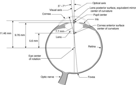
Figure 1 shows some of the structures and dimensions of the eye that are important in eye movement measurement (1,2). In an idealized model, the optical axis of the eye is the line that passes through the centers of curvature of the cornea, and lens, and the center of rotation of the eyeball. The visual axis (or line of sight) is the ray that passes from the fovea, through the nodal points of the lens and inter-
sects the point-of-gaze. It is important to note that the fovea is not centered on the retina, but rather is located 5–78 toward the temporal side. The visual and optical axes are therefore, not identical. An idealized model of the eye usually assumes the pupil and iris to be centered on the optical axis, and assumes that the eyeball and eye socket operate as a perfect ball and socket joint, with the eyeball rotating about a single point within the eye socket.
The idealized model is often perfectly adequate for making good measurements of gaze direction and eye movement dynamics, but is not precisely accurate. For example, the eye does not rotate about a single center of rotation within the eye socket (3). The pupil is not precisely centered with respect to the optical axis, visual axis, or iris, and its center moves as the iris opens and closes (4).
Eye position with respect to the head can be described by a three element rotation vector, by a four element rotation specification called a quarternion, or by a set of three angles that describe the positions of an imaginary set of nested gimbals, with the outer gimbal fastened to the head, and the eye attached to the inner most gimbal. In the latter case, the three angles are usually referred to as Fick or Euler angles, and consist of an azimuth (or horizontal) angle, an elevation (or vertical) angle, and a roll (or torsion) angle. In all cases rotations are measured from a somewhat arbitrary reference position that loosely corresponds to looking straight ahead when the head is upright. A complete description of the methods and underlying mathematics for specifying eye rotation is available in an article by Haslwanter (5).
Gaze tracking devices usually report point-of-gaze in terms of a coordinate system defined on a surface in the
Figure 1. Schematic diagram of the eye showing typical values of dimensions that are important in eye movement measurement. The dimension values, which do vary between individuals, are derived from Refs. 1 and 2.
environment; or an eye location in space plus a gaze direction vector, with respect to an environment coordinate frame.
Normal human eye movements fall into the broad categories of conjugate and nonconjugate movements. Conjugate movements, in which both eyes move together, include the rapid, ballistic jumps between fixation points, called saccades; smooth compensatory movements to hold the gaze steady in the presence of head motion; smooth movements to track objects that are moving across the visual field; and the saw tooth pattern of movement called nystagmus that occurs in response to an inertial rotation of the body or a rotation of the visual field. There are also miniature motions during the relatively stationary fixation periods, which are < 18 and are not perceived. Vergence is a nonconjugate motion used to keep a visual target at the same position on both retinas. As a visual target moves closer, the visual axes of the two eyes rotate toward each other. Ocular torsion occurs in response to inertial rotation or lateral acceleration, or rotation of the visual field about a horizontal axis. It is associated with perceptions of tilt. A thorough review of eye movement behavior can be found in Hallett (6).
The eye movement measurement techniques currently in most frequent use fall into the major categories of magnetic search coil, a technique that measures magnetically induced current in a tiny wire coil fastened to the eye; electrooculography, which uses surface electrodes to measure the direction of an electrical potential between the cornea and retina; and optical techniques that rely on optical sensors to detect the position or motion of features on the eye. Their optical technique category includes many subcategories, and has the largest variety of different systems in current use. Background theory and system descriptions for eye movement measurement devices, in all of these categories, are presented in the following sections.
Eye tracker performance is usually described by some subset of the following parameters. Accuracy is the expected difference between the measured value and the true
EYE MOVEMENT, MEASUREMENT TECHNIQUES FOR |
265 |
value. Resolution is the smallest change that can be reported by the device. Precision is the expected difference in repeated measurements of the same true value. Range describes the span of values that can be measured by the device. Linearity is the degree to which a given change in the real quantity results in a proportional change in the measured value, usually expressed as percent of the measurement range. Update rate is the frequency with which data is output (samples per second). Bandwidth is the range of sinusoidal input frequencies that can be measured without significant distortion or attenuation. Transport delay is the time required for data to pass through the system and become available for use.
SCLERAL SEARCH COIL
The scleral search coil technique, first described by Robinson (7), requires that a sensing element be placed on the eye. The technique is based on the principle that a changing electric field can induce a current in a coil of wire. If the coil lies in a plane parallel to a uniform, alternating current (ac) magnetic field, no current is induced. If the plane of the coil is not parallel to the field lines, an ac current will be induced in the coil. Current amplitude will be proportional to the coil area projected onto the plane that is perpendicular to the magnetic field lines. For example, if the plane of the coil is tilted about an axis perpendicular to the magnetic field lines, the induced current will be proportional to the sine of the tilt angle. A tilt in the opposite direction results in an induced current with the opposite phase (1808 phase shift). The sign of the tilt angle can, therefore, be deduced from the phase of the induced current.
As shown in Fig. 2, a pair of Helmholz coils, which set up uniform ac magnetic fields in both vertical and horizontal axes, surrounds the subject’s head. The driving circuitry ensures that the two fields are exactly 908 out of phase. An induction coil, made of very fine wire, is held on the eye so
Pair of vertical field coils
Pair of horizontal field coils
Phase |
Filtering, |
Vertical |
|
calibration |
|||
sensitive |
eye pointing |
||
detector |
& |
direction |
|
linearization |
Phase |
Filtering, |
Horizontal |
|
calibration |
|||
sensitive |
eye pointing |
||
detector |
& |
direction |
|
linearization |
|||
|
Current |
90 deg |
Oscillator |
|
amplifier |
phase |
||
(20 kHz) |
|||
(vertical) |
shifter |
||
|
Current amplifier
(horizontal)
Figure 2. Schematic illustrating the scleral search coil method of measuring eye movement. (Adapted from a diagram in Ref. 8.)
266 EYE MOVEMENT, MEASUREMENT TECHNIQUES FOR
that it forms a circle about the limbus (iris–sclera boundary). Robinson embedded the coil in a scleral contact lens, which was held to the limbus by the action of a tiny suction tube. Collewijn et al. (9) developed a technique for using an annular ring made of silicone rubber and having a slightly hollow inner surface. The ring adheres to the limbic area by capillary action and does not require the suction tube. Fine wire leads, from the induction coil, extend out of the eye at the canthus (the corner of the eye). A drop of anesthetic is generally administered prior to insertion, but the devise is usually tolerated well once the anesthetic wears off (9).
The induction coil encloses an area that is approximately in the plane of the pupil. Horizontal eye movement varies the current induced by the horizontal ac magnetic field, and vertical motion varies the current induced by the vertical field. By detecting the phase, as well as the amplitude of the induced current, it is possible to obtain separate analog signals proportional to the sine of vertical and horizontal eye rotations. A simple calibration is required to find the initial reference orientation of the eye.
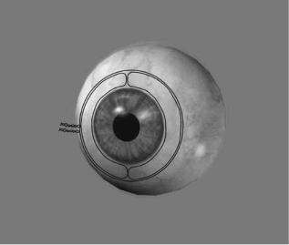
It is possible to embed, in the annular ring, a second induction coil that encloses an area having a component parallel to the optical axis of the eye. The second coil is shown in Fig. 3. Torsional eye movement can be computed from the current induced in this second coil.
When used with nonhuman primates, a magnetic induction coil is often implanted surgically, using a method described by Judge et al. (10).
Scleral search coil systems can be expected to measure with a resolution > 1 arc min over a range of 15–208, and accuracy of 1–2% of the range. Slippage of the annular ring on the eyeball is possible, and can produces significant additional error. Temporal bandwidth is a function of the coil excitation frequency and filtering, and depends on the
Figure 3. Schematic showing the configuration of the second coil in a dual induction coil system. The second coil forms a loop whose enclosed area has a component parallel to the optical axis of the eye (perpendicular to the plane of the pupil), and is used to measure torsional movement. Although the diagram shows only one winding for each coil, the actual device uses multiple windings.
specific implementation, but 0–200 Hz or better is probably achievable. The accuracy of the torsional measurement is generally assumed to be a fraction of a degree, but may be affected by slippage of the annulus as well as variation in eyeball curvature, and is not well documented.
The method is distinctly invasive, and requires the head to be confined within the Helmholz coil assembly, but does not require the head to be rigidly fixed. It offers good measurement performance, measures all three axes of rotation simultaneously, and is not affected by eyelid closure, or ambient illumination. In the past, complete systems for use with humans have been commercially available from C-N-C Engineering, Seattle, WA; and Skalar Medical BV (11), The Netherlands. Current commercial availability is uncertain. Systems for use with animals are available from Riverbend Instruments, Inc., Birmingham, AL (12).
ELECTRO-OCULOGRAPHY
Electro-oculography (EOG) has a relatively long history, dating from the 1920s and 1930s (13–17). The retina of the eye carries a slightly negative electrical charge, varying from 0.4 to 1.0 mV, with respect to the cornea, probably because the retina has a higher metabolic rate. This charge difference constitutes an electrical dipole, which is approximately, although not exactly, aligned with the optical axis of the eye. Electro oculography refers to the use of surface skin electrodes to measure the position of the cornearetinal dipole. When used with ac recording techniques to measure nystagmus, or when used in a neurological test setting to measure any type of eye movement, it is often called electronystagmography (ENG).
Ideally, when the electrical dipole is midway between two electrodes that have been placed near the eye, the differential voltage between the electrodes would be zero, and as the eye rotates from this position, the differential voltage would increase with the sine of the angle. Although this is indeed the qualitative result, in practice there is a great deal of direct current (dc) drift. Skin conductance varies over time, and the corneo-retinal potential changes with light adaptation, alertness, and the diurnal cycle. In fact, EOG is sometimes used explicitly to measure the changes in corneo-retinal potential as a function of light stimuli, rather than eye movement (18,19). Electromyographic activity from facial muscles can also interfere with EOG measurement.
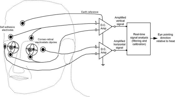
After cleaning the skin with an alcohol swab, electrodes are often placed as shown in Fig. 4. In this case, the differential voltage between the electrodes placed near the outer canthi (junction of upper and lower eyelid) of each eye is used to measure horizontal motion of the two eyes together. It is also possible to use additional electrodes near the nose, or on the bridge of the nose, to measure the two horizontal eye positions independently. The vertically positioned electrode pairs measure both eyes together when wired as shown in the diagram, but can also be used to measure vertical position of each eye, independently. The electrode at the center of the forehead is used as a reference. Other placement patterns can be used as well.
EYE MOVEMENT, MEASUREMENT TECHNIQUES FOR |
267 |
Figure 4. Schematic illustrating the EOG method of measuring eye movement. (Adapted from a diagram in Ref. 8.)
The electrodes most often used are silver–silver chloride, self-adhesive models, designed as infant heart monitor electrodes. They are connected to high gain, low impedance, low noise, differential amplifiers. The output from the differential amplifiers is now most commonly digitized and input to digital processors for linearization, scaling, and other processing. The ac coupling or frequent rezeroing is required to keep the analog signal in range of the analog to digital converters.
The high and unpredictable rate of dc drift makes this technique less suitable than others for point of gaze measurement. However, the drift is usually slower than eye movement velocities, and EOG provides an excellent means for measuring eye velocity profiles, slow and fast phases of nystagmus, and patterns of fixations and saccades, as long as the precise point of regard is unimportant. Research laboratories often assemble their own EOG devices from commercially available amplifiers, electrodes, and digital data processing software packages. Both EOG and ENG devices are sometimes used for neurological testing in clinical settings, and commercially available EOG or ENG devices are most often packaged as part of neurological testing suites.
The EOG and ENG systems are commercially available from: Cambridge Research Systems Ltd., UK (20); GN Otometrics, Denmark (21); Guymark UK Ltd., UK (22); Metrovision, Pe´renchies, France (23), and Neuro Kinetics, Inc., Pittsburgh, PA (24).
OPTICAL TECHNIQUES
Noncontacting optical sensors can be used to deduce the orientation of the eyeball from the position of optical features, optically detectable geometry, or the pattern of reflectivity on the eye and the facial area surrounding
the eye. The sensors may range from a small number of individual photodiodes to CCD or CMOS arrays, which provide two-dimensional (2D) gray scale image data. In most cases the eye area is illuminated with a near infrared (IR) light that is within the sensitive spectral region for solid-state light sensors, but minimally visible to the human eye. Optics may be mounted to head gear and move with the head, the head may be restrained to prevent or limit motion with respect to optics that are not head mounted, or movement with respect to non-head-mounted optics may be allowed. In the latter case the sensor field of view must either be large enough to accommodate the expected head movement, or some component of the optical assembly must automatically move to keep the sensor aimed at the eye being measured.
OPTICAL SENSORS
Sensors used by optical eye trackers include the following: Quadrant and bicell photodetectors: The disk shaped detector surface is divided into two (bicell) or four (quadrant) discrete photosensitive areas. The devices are configured to produce analog signals (one for bicell detectors, and two for quadrant detectors) proportional to the difference in light intensity sensed on adjacent areas. The signals are monotonically related to small displacements of a light spot from the center of the detector either in one (bicell) or two (quadrant) dimensions. The light spot must remain completely on the detector surface, and displacements must be smaller than the diameter of the spot.
Lateral effect photo diodes (position sensitive detectors): A solid-state detector provides analog information proportional to the one (1D) or two dimensional location of the incident light center of gravity. Small arrays of discreet solid state photosensors: The array provides a small number of
268 EYE MOVEMENT, MEASUREMENT TECHNIQUES FOR
analog light intensity signals. Large, linear, photo-sensor arrays: The array provides gray scale image data in a single dimension. Large, 2D, solid-state, photosensor arrays (CCD and CMOS): The array provides two dimensional gray scale image data. Commercially available video cameras, based on CCD and CMOS sensors provide analog and digital signals in standard formats, usually at 50 or 60 fields/ second. Using a CCD chip that supports double the normal pixel output rate, a small number of cameras are available that output 120 fields/second. By using a subset of the video lines for each field, these devices can also deliver field update rates that are higher than 120 Hz. Some CMOS sensor chips allow even more flexibility to receive data from a dynamically determined subset of the pixels and to vary the update rate. Higher update rates always mean that each pixel has less time to accumulate charge, resulting in less effective sensitivity and lower signal to noise ratios.
Quadrant detectors, lateral effect photo diodes, and small arrays of discrete photo sensors provide information with low spatial bandwidth content. The information can usually be processed at high temporal bandwidth with relatively little digital processing requirement. Large linear and 2D arrays offer much richer spatial information, but require more processing power to interpret the information, often leading to reduced temporal bandwidth.
FEATURES OF THE EYE
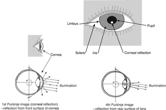
The eye image features most often used for eye movement measurement are Limbus: Boundary between the colored iris and white sclera. Iris: ‘‘Colored’’ ring that opens and
closes to adjust pupil size. Pupil: Circular opening defined by inner boundary of iris. First Purkinje image (corneal reflection): Reflection of a light source from the outer surface of the cornea. Fourth Purkinje image: Reflection of a light source from the inner surface of the lens.
These features are shown schematically in Fig. 5. The pattern of blood vessels on the retina, if imaged with
an opthalmoscope or fundus camera, also constitute markings that can be used to track eye movement, but this is a less commonly used technique.
In some cases facial landmarks, such as the canthus (corner of the eye, where the upper and lower eyelid meet), another facial feature, or a dot placed on the skin, may be used to compare with the location of features on the eye. As discussed later on, facial features can also be used to guide remote camera based trackers.
The iris has a distinctive pattern of radial markings that can be used to track ocular torsion. Its inner boundary, defining the pupil, is nominally circular and centered with respect to the limbus. Detailed examination, however, reveals a slightly noncircular shape that is off center (usually toward the nasal side) with respect to the limbus. Furthermore, both the shape and position of the pupil change slightly with pupil diameter and vary across the population. The characteristics of the pupil form are described and quantified in considerable detail by Wyatt
(4). He found that pupil position tends to shift in the nasal and superior directions (with respect to the limbus) as the pupil contracts, and that pupil diameter and circularity tend to decrease with age.
Light rays that enter the eye through the pupil are reflected by the retina and directed back toward their
Figure 5. Schematic illustrating the various features of the eye often used by optical eye movement measurement techniques. (Adapted from a diagram in Ref. 8.)
EYE MOVEMENT, MEASUREMENT TECHNIQUES FOR |
269 |
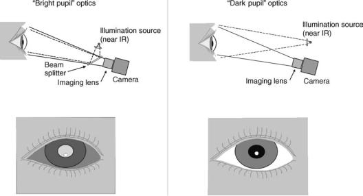
Figure 6. Illustration of bright and dark pupil optics. In the bright pupil example, retroreflected light from the retina will beam back into the camera lens, resulting in a bright, back lit, pupil image.
source. The eye therefore acts as a retroreflector. If the eye is viewed by a detector that is coaxial with an illumination beam, as shown in Fig. 6, the retroreflected light from the retina makes the pupil appear to be a bright, back lit circle. Some of the retinal reflection can be received slightly off axis from the illumination beam (25). Although the bright pupil effect falls off sharply as the detector moves off axis, this accounts for the ‘‘red eye’’ effect in flash photography. In an idealized case, the apparent brightness of the pupil retroreflection will vary inversely with the square of pupil diameter (26). As shown by Nguyen et al. (25), brightness of the retinal reflection also varies between individuals and as a function of gaze direction with respect to the illumination source, but these variations are small compared to the effect of pupil diameter.
If the detector is off axis from the illumination beam, the retroreflected light does not enter the detector and the pupil appears as the familiar dark circle.
The corneal reflection is a virtual image that appears to be just behind the plane of the pupil. If the cornea is assumed to be spherical, the corneal reflection image will form at point half way between the surface of the cornea and its center of curvature, along a ray that is parallel to the illumination beam and passing through the corneal center of curvature. If the light source is far away compared to the radius of the eyeball, then as the eye rotates, the corneal reflection always appears to move the same amount as the corneal center of curvature. A similar analysis will show that the fourth Purkinje image forms in almost the same plane as the corneal reflection, but appears to move the same amount as the posterior lens surface center of curvature.
FEATURE RECOGNITION
Systems that use 2D detector arrays typically perform a pattern recognition task to identify features in the 2D
image. Digital processing power has always been a critical limitation. When video cameras were first used as sensors, analog preprocessing was often used to find edge points, or other pixel subgroups, and thereby reduce the amount of data that needed to be processed digitally. Algorithms requiring relatively few computational steps were used to process the reduced digital information in order to recognize features and find their centers.
Increased digital processing capability has very significantly eased, although by no means eliminated, this limitation. It is now practical to digitally process 2D, gray scale image buffers while maintaining reasonable, real-time update rates. It has become possible to use, in real-time, elements of classical digital image processing such as Sobel or other convolution based edge detection algorithms, and circle or ellipse best-fit algorithms. Less computationally intensive algorithms are still often used, however, to maximize update rates.
Digital processing components in current use range from commercially available PCs and frame grabbers to custom processing boards that include field programmable gate arrays (FPGAs) and digital signal processors (DSPs), and microcontrollers.
When using an array sensor, the location of individual boundary points on an image feature (e. g., the pupil) are often identified with only single pixel resolution. If the object covers multiple pixels, knowledge of the object shape allows its position to be computed with subpixel resolution. For example, if a group of pixels are thought to define the edge of circular object, a least mean squared error circle fit will define the circle center location with sub pixel resolution. If sufficient computation time is available, it is also possible to use gray scale information to define edge points with subpixel accuracy.
Pupil Recognition
The pupil is generally recognized as a circular or elliptical area that is darker (in the case of a dark pupil image) or
270 EYE MOVEMENT, MEASUREMENT TECHNIQUES FOR
brighter (in the case of a bright pupil image) than surrounding features. The pupil is often partially occluded by eyelids and corneal reflections, and algorithms must therefore recognize the circular or elliptical shape even when occluded to some degree. Furthermore, it is important that only the real pupil boundaries be used to determine the center of the object, rather than the occlusion boundaries. Examples of pupil detection algorithms can be found in Zhu (27), Mulligan (28), Ohno et al. (29), Charlier et al. (30), and Sheena (31).
The retroreflective property of the eye makes possible a signal enhancement technique that can be exploited to help identify the pupil (32–35). If a camera is equipped with both a coaxial and off-axis illuminator, a bright pupil image will be produced when only the coaxial illuminator is on, and a dark pupil image will be produced when only the offaxis source is on. If the illuminators are alternately activated for sequential camera images, the result will be alternating bright and dark pupil images. Assuming elements in the camera field of view have not moved between images, all other image features, which are not retroreflectors, will remain essentially unchanged.
If two such images are subtracted, one from the other, the result should leave only the pupil image. In practice, there will still be small differences in all parts of the image due to the different illumination angles, but contrast between the retroreflective pupil and the rest of the image is still greatly enhanced. There are some drawbacks to the technique. If the eye moves significantly between the sequential images, subtraction results in a distorted pupil image. The need to digitize and subtract two images increases memory and processing requirements, and the fact that two sequential images are required to create one data sample limits the temporal bandwidth of the measurement. Note that a similar result can be obtained with images from two cameras that are carefully aligned with respect to the same image plane, and an illumination source that is coaxial with only one of them.
Corneal Reflection Recognition
The corneal reflection (first Purkinje image) is usually recognized, within a larger 2D image, by its intense brightness, predictable size and shape, and proximity to the pupil. It can, however, be confused with small reflections from tear ducts or eyeglass frames, and reflections from external sources emitting light in same spectral band as the intended source. Its center can be identified with subpixel accuracy only if it is large enough to cover multiple pixels. Eizenman et al. (36) describe a technique for using knowledge of brightness pattern across the corneal reflection (first Purkinjie image) to find its position, on a linear array, with subpixel resolution. To accomplish this they used a precisely designed illumination source to insure a known pattern of luminance.
Fourth Purkinje Image Recognition
The fourth Purkinje image is very dim and very difficult to reliably identify in a larger image. The one system in common use that requires the fourth Purkinje image relies on careful initial alignment to focus the image on a quad-
rant detector. The detector is not much larger than the Purkinje image; and, in this case, automatic recognition in a larger field is not necessary.
Face Recognition
In some cases wide-angle images are now used to recognize the presence of a face, and to find the location of one or both eyes. If the eye is identified in a wide angle image, and assuming the camera is well calibrated to account for lens or sensor distortions, it is reasonably straight forward to compute the direction of the line extending from the camera to the eye. Finding the distance to the eye is more difficult. If the eye is identified on the images from two cameras, it is possible to triangulate. If both eyes are identified on a single camera image, knowledge of the true interpupillary distance can be used to compute distance to the face. However, head rotation with respect to the camera will cause some error if not taken into account. Some face recognition systems are able to determine head orientation. For example, Xiao et al. (37) and Matthew and Baker (38) describe a method, based on a technique known as active appearance modeling (39), to make real-time measurements of the position and 3D orientation of a face.
Information about eye location can be used to direct a separate sensor to obtain a more magnified view of the eye, or the wide-angle image itself may also be used to find the position of features within the eye. In the latter case, there is a clear trade off between spatial resolution and wideangle coverage. Recognition of facial features can also be exploited in order to use a facial landmark, such as the canthus or the center of the eyeball as one of the elements in a dual feature-tracking algorithm (40,41). However, the plasticity of facial features makes it difficult to determine their position with the same precision as the pupil and Purkinjie images.
EYE ORIENTATION AS A FUNCTION OF SINGLE OR DUAL FEATURE POSITION
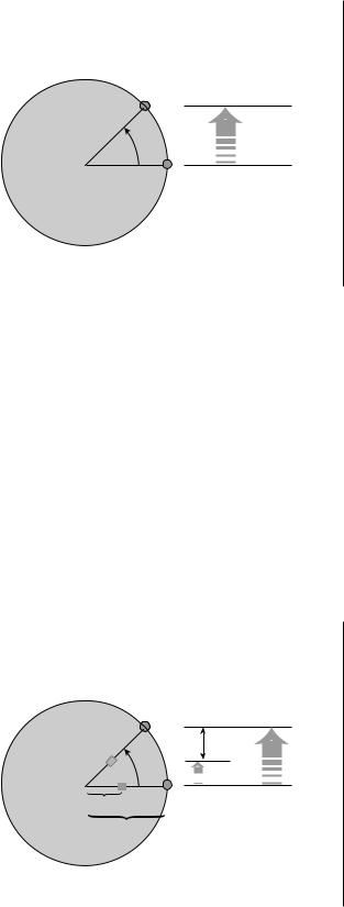
If we have a sphere of radius r, with a mark on its outer surface as shown in Fig. 7, and if we assume the center of the sphere is fixed with respect to an observer, then the observer can compute the rotation (u) of the sphere about its center by noting the displacement (d) of the surface mark.
u ¼ arcsinð d=rÞ
This is the principle behind single feature eye tracking. However, if the center of the sphere moves with respect to the observer, observation of a single mark provides no way to distinguish such motion from rotation.
If there are two visible marks on the sphere, which are fixed to the sphere at different distances from its center, then observing the relative position of these marks does allow rotation of the sphere to be distinguished from translations. So long as the distance between the sphere and observer remains the same or is independently known, translation with respect to the observer can be unambiguously distinguished from rotation.
Detector
plane
θ |
d = r sin(θ) |
|
r
Figure 7. Schematic illustrating the principle behind single feature tracking. Observation of a single land mark on the sphere allows determination of its orientation, so long as the center of the sphere does not move.
If the two marks are located along the same radius line, at distances r1 and r2 from the center of the sphere, as shown in Fig. 8, then the rotation angle (u) of this radius line, with respect to the line connecting the sphere and observer, is
u ¼ arcsinð Dd=ðrlr2ÞÞ
where Dd is the observed separation between the marks. This is the basic principle behind dual feature tracking techniques. The underlying sine function has a steep slope at small angles, maximizing the sensitivity of the technique. Note that if the distance between the observer and sphere changes, the dual feature relation still leaves some
Detector
plane
∆d
q |
r2 sin(q) |
 r1 sin(q)
r1
r2
∆d = (r2–r1) sin(q)
Figure 8. Schematic illustrating the principle behind dual feature tracking. The relative position of the two landmarks defines the orientation of the sphere, even if its center moves in a direction parallel to the plane of the detector.
EYE MOVEMENT, MEASUREMENT TECHNIQUES FOR |
271 |
ambiguity since the apparent separation between the marks will change as a function of distance.
In the case of the eye, referring to Fig. 1, the center of the pupil or center of the iris is a mark that is 9.8 mm from the center of the eyeball. Although both images appear to be just behind the plane of the pupil, the first Purkinje image moves the same amount, with eye rotation, as would a mark 5.6 mm from the center of the eyeball (the position of the anterior corneal surface center of curvature); and the fourth Purkinje image moves the same amount as would a mark 11.5 mm from the center of the eyeball (the position of the posterior lens surface center of curvature).
Eye Orientation as a Function of Just Pupil or Corneal Reflection Position
The pupil, and corneal reflection (first Purkinje image) are the features most commonly used for single-feature tracking. If a sensor and light source are mounted so that they do not move with respect to a person’s head, either of these features can be used as a marker to compute eye rotation in the eye socket. Either the head must be stabilized with some type of head restraint mechanism, or the sensor must be mounted to head gear that moves with the subject.
When measuring only a single feature, any translation of the head with respect to the sensor will be erroneously interpreted as eye rotation. For example, if using pupil position, a 1 mm motion of the head parallel to the detector image plane may be mistaken for about a 58 eye rotation. If the corneal reflection is the feature being tracked, a 1 mm slippage will be indistinguishable from an 128 eye rotation.
Eye Orientation as a Function of Relative Pupil and Corneal Reflection Positions (CR/Pupil)
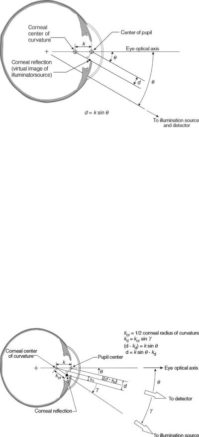
The pupil and first Purkinje image (corneal reflection), or the first and fourth Purkinje image are the most commonly used feature pairs for dual feature tracking. The pupil to corneal reflection technique (CR/Pupil) was first described by Merchant et al. (42). As shown in Fig. 9, if the sensor is close to the light source that produces the corneal reflection, the angle (u) of the eye optical axis with respect to the sensor is described by
u ¼ arcsinð d=kÞ
where d is the apparent distance between the pupil and corneal reflection (from the point of view of the sensor), and k is the distance from the pupil to the corneal center of curvature. If the sensor is not close to the illumination source,the relationchangesonly slightlysolongasthesensor does not move with respect to the illumination source.
u ¼ arcsinððd kdÞ=kÞ
kd ¼ kcrsinðgÞ
where kcr is half the cornea radius of curvature and g is the angle between the illumination beam and the sensor line of sight (see Fig. 10). If the sensor and illumination source are very far away, compared to the radius of the eyeball, then g,
272 EYE MOVEMENT, MEASUREMENT TECHNIQUES FOR
Figure 9. Schematic illustrating the basic relationship behind the pupil-to-corneal-reflection technique for measurement eye movement. The diagram assumes that the detector and illumination source are coaxial, or very close together, and are very far from the eye, compared to the radius of the eyeball. The optical axis of the eye is rotated away from the detector by an angle u. From the vantage point of the detector, the pupil and corneal reflection appear to be separated by distance d.
and hence kd, are constants. One drawback to the pupil to corneal reflection technique is that the pupil center is not completely stable with respect to the optical or visual axis, but moves slightly as the pupil size changes (4). Theoretically, this effect can be measured in an individual and accounted for (43,44), but would add to the time and effort required to calibrate an individual. Note also that the pupil-to-corneal-reflection vector is less sensitive to eye rotation than either of the individual features. A 58 eye rotation, from an initial position in which the pupil and corneal reflections are aligned, causes the pupil and corneal reflection images to separate by only 0.4 mm, whereas the pupil center moves 1 mm.
The equations given above describe the major effect, but not all secondary effects, and are not precise. For example, the cornea is not perfectly spherical, the eyeball does not rotate about a perfectly stable central point, and the pupil image is slightly magnified by the refractive power of the cornea. To the extent that secondary effects are large enough to be detected, they are often accounted for by the results of an empirical calibration procedure, as discussed later.
The range of gaze angles that can be measured by the pupil to corneal reflection technique is limited by the range over which the corneal reflection remains visible to
the detector. In the horizontal axis, this range is usually708 visual angle for a given illumination source and sensor pair. It is usually less in the vertical axis due to occlusion of either the pupil or corneal reflection by the eyelids. The range can be extended by using multiple illumination sources, at different positions, to create multiple corneal reflections, but the system must be able to uniquely recognize each reflection even when not all are visible.
Eye Orientation as a Function of Relative First and Fourth Purkinje Image Positions (CR/4PI)
As described by Cornsweet and Crane (45), the first and fourth Purkinje images can also be used for dual feature tracking. The same type of arcsine relation applies, but with d the apparent distance between the two Purkinje images, and with k equal to the distance between the corneal center of curvature and the posterior lens surface center of curvature. The technique has the advantage that the Purkinje image positions can be more precisely defined than the pupil center. In addition, the separation of the posterior lens surface and corneal centers of curvature ( 6 mm) is greater than that between the pupil and corneal centers of curvature ( 4.2 mm), yielding greater
Figure 10. Schematic illustrating the detected pupil to corneal reflection separation (d) when the detector and illuminator optical paths are not coaxial. The diagram assumes that the detector and illumination source are far from the eye, so that lines from the detector to various points on the eye are essentially parallel, as are rays from the illumination source to various points on the eye. The angle u is between the eye and detector optical axes, and g is the angle between the detector optical axis and the illumination beam.
sensitivity to eye rotation than the pupil to corneal reflection technique. Drawbacks are that the fourth Purkinje image is relatively dim and difficult to find, and is only visible within the iris opening.
Eye Orientation as a Function of Relative Pupil or Iris and Facial Landmark Positions
The relative position of the pupil or iris and a facial landmark can also be used to measure eye orientation. This is sometimes done when image magnification and resolution is such that the smaller Purkinje images cannot be reliably detected, or the relative motion of the pupil and corneal reflection cannot be sufficiently resolved. Since the facial landmark does not move with eye rotation, the governing relationship is described by
u ¼ arcsinð ðd diÞ=rÞ
where d is the distance (in the camera image plane) from the facial landmark to the pupil or iris center, di is the distance (also in the camera image plane) from the facial landmark to the eye center of rotation, r is the distance from the pupil or iris center to the eyeball center of rotation, and u is the angle of the eye optical axis with respect to the detector. If the head rotates with respect to the detector, di will appear to shorten, in the direction perpendicular to the rotation axis, by an amount proportional to the cosine of the rotation angle. Advantages over other dual feature techniques are greater sensitivity (larger change of the measured quantity for a given eye rotation), and the possibility of identifying the features in wider, less magnified images. Disadvantages are that facial image features are not stable, but usually move at least slightly as a function of facial muscle activity, and head orientation must also be measured or must remain stable with respect to the detector. Zhu and Yang (40) describe a dual feature technique using the relative position of the canthus and iris; and Tomono et al. (41) describe an algorithm for using the relative position of the pupil, and a computed position of the center of the eyeball.
EYE ORIENTATION AS A FUNCTION OF FEATURE SHAPE
It is also possible to extract eye orientation information from feature shape. A circle (e. g., the pupil outline or outer boundary of the iris) appears elliptical if viewed from an angle. As the circle tilts, the minor axis of the ellipse, which is perpendicular to the axis of rotation, appears shortened by the cosine of the rotation angle. A major drawback to using pupil or iris ellipticity as an orientation measure is that, due to symmetry considerations, the direction of rotation about the rotation axis remains ambiguous. A second major limitation is that the underlying cosine function has a shallow slope at small angles resulting in poor sensitivity.
EYE ORIENTATION AS A FUNCTION OF REFLECTIVITY PATTERN MOVEMENT
Different structures on the eye, primarily the pupil, iris, and sclera have different reflectivity properties. As the eye
EYE MOVEMENT, MEASUREMENT TECHNIQUES FOR |
273 |
rotates this reflectivity pattern moves, and that property can be exploited to measure eye movement. Movement of the reflectivity pattern can be detected with small numbers of individual photodetectors, and this, in turn, makes it possible to achieve relatively high temporal bandwidth. The technique was pioneered by Torok et al. (46) and Smith and Warter (47), using a photomultiplier as the detector, and further developed by Stark and Sandberg (48), Wheeless et al. (49), Young (50), Findlay (51) and Reulen et al. (52). The most prominent contrast feature in the pattern is generally produced by the boundary between the iris and sclera. Therefore, devices that use small arrays of photodetectors to measure motion of this pattern are often called limbus trackers.
The iris sclera boundary is easily visible along the horizontal axis, but along the vertical axis it is usually obscured by the eyelids. In fact the boundary between the eyelids and iris are often the most prominent reflectivity boundaries along the vertical axis. The eyelids do tend to move in proportion to vertical eye motion, and are useful as measures of vertical eye position; but motion of the reflectivity pattern remains a much less dependable function of vertical (as opposed to horizontal) eye rotation.
In principle, reflectivity pattern tracking is similar to single feature tracking. As with single feature tracking, any movement of the sensors with respect to the eye produces erroneous measurements.
MEASURING POINT-OF-GAZE IN THE PRESENCE OF HEAD MOTION
Dual feature techniques, such as the pupil to corneal reflection method, permit computation of gaze direction with respect to a detector. However, head motion may still need to be measured in order to accurately determine the point of gaze on other objects in the environment.
First, consider an example in which the head is free to move with respect to a stationary detector, and the task is to measure point of gaze on other stationary objects in the environment. This is illustrated by the two dimensional example in Fig. 11. The point of gaze, defined by x, is dependent not only on u, which can be measured by one of the dual feature tracking methods previously described, but also on f and d1, which define head position. If head motion is small compared to distance to the detector and scene surface, then changes in head position will have little effect and can be ignored.
If the location of the eye in the environment space can be independently measured, and if the detector and scene surface positions are known with respect to the same environment space, the following general algorithm can be used to determine point of gaze on a surface. Use a dual feature technique to determine direction of the gaze vector with respect to the detector, and knowledge of the detector orientation to express this as a direction in the environment space. Use the gaze direction and known start point (the location of the eye in space) to write the parametric equation for a line in the environment coordinate space. Use knowledge of the scene surface position to solve for the intersection of a line and a plane. Ohno et al. (29) describe a version of this strategy.
274 EYE MOVEMENT, MEASUREMENT TECHNIQUES FOR
Scene
d 2
Point-of-gaze on scene
Eye
θ
x
φ
d 1
d1 sinq – d2 cos(f+q) |
Detector |
|||
|
||||
x = |
|
|
|
|
sin(f+q) |
Plane parallel to scene |
|||
|
||||
Figure 11. Relationship, in one plane, between point-of-gaze on a flat scene and relative eye, detector, and scene positions. (From Ref. 26.)
Next, consider an example in which the detector is fastened to headgear worn by the subject. Single as well as dual feature techniques may be adequate to measure gaze direction with respect to the head (although single feature methods will have larger errors if there is any slippage of the headgear). In order to find point-of-gaze on objects in the environment it is clearly necessary to know the position and orientation of the head with respect to those objects. The following strategies can be used.
1. A second camera can be mounted to the head gear so that it shares the same reference frame as the eye sensor, but points toward the subject’s field of view. Point-of-gaze can be indicated as a cursor superimposed on the image from this scene camera.
2. Light-emitting diodes (LEDs) or other special emitters can be fastened to an object in the environment, such as the bezel of a computer monitor, and detected by head mounted sensors to locate the object in the head reference frame. Measurement of gaze in the
Apparent point of gaze in scene camera image
Scene camera |
|
|||
|
|
|
|
Parallax error |
|
|
|
|
|
|
|
|
|
|
|
|
|
|
|
|
|
|
|
Line of gaze |
Eye |
Actual point of gaze |
|||
head reference frame can then be related to position on that object.
3. A separate head tracking system can be used to measure head position and orientation with respect to the environment. This information can then be used to compute the location and direction of the gaze vector in the environment coordinate frame. If the locations of surfaces are also known in the same environment reference frame, it is possible to solve for the intersection of a line (line-of-gaze) with a surface, to find point-of-gaze on various surfaces in the environment. A general method for doing this computation is described in Appendix E of Leger et al. (8). Duchowski (53) also describes specific algorithms for handling this type of task.
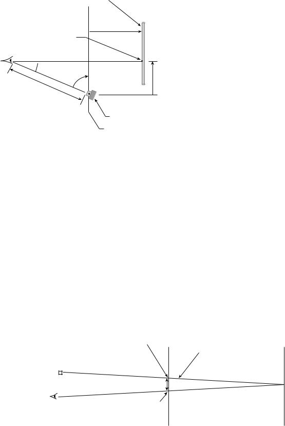
In the case of the head mounted scene camera described above, it is important to be aware of possible parallax error. The scene camera is usually not viewing the scene from exactly the same vantage point as the eye being tracked. As shown in Fig. 12, eye rotation angle data can be mapped to the scene camera image plane at a particular image plane distance, but the relation changes as the image plane distance changes. The resulting parallax error can be easily corrected if there is knowledge of the distance, from he subject to the gaze point. The parallax error may be negligible if the distance to the gaze point is large compared to the distance of the scene camera from the eye. It is also possible, as shown in Fig. 13, to minimize parallax by bending the scene camera optical path with a beam splitter, such that the scene camera has the same vantage point as the eye being measured (54).
If a person with normal ocular function is fixating a point not infinitely far away, the lines of gaze from the two eyes should converge. If the gaze angles of both eyes are measured with head mounted optics, the intersection of the two lines-of-gaze theoretically indicates the threedimensional (3D) point-of-gaze in space, with respect to a head fixed coordinate system. If head position and orientation are known, this can be transformed to a position in environment space. Duchowski (53) describes an algorithm for this computation. It should be noted that, in practice, the measured lines-of-gaze from the two eyes will almost
Line along which point of gaze will be mapped in scene camera field of view
Scene plane |
Calibration plane |
Figure 12. Parallax error when gaze direction is mapped (calibrated) to a scene camera image plane that is different from the plane being fixated.
Beam splitter
Eye 
Scene camera
Figure 13. Use of a beam splitter to minimize scene camera parallax.
never intersect. Neither the measurement nor the system being measured is infinitely precise. The discrepancy can be resolved as follows. Consider the two planes that are parallel to the ‘‘vertical’’ axis of the head and which contain the gaze vector from each of the two eyes. If the two lines-of- gaze converge, these two planes will intersect along a line, which is also intersected by the line-of-gaze from each eye. The 3D point-of-gaze can be chosen to be either of these intersection points or a point half way between the two.
As the point-of-gaze moves farther from the head, the vergence angle (the angle formed by the gaze vector from each eye) diminishes. The relation is reasonably sensitive at close distances. As distances become longer, a very small change in vergence corresponds to an increasingly large change in distance, and moderate measurement noise or error in the eye tracker may result in a very noisy or inaccurate point of gaze computation.
MEASUREMENT OF TORSIONAL EYE MOVEMENT
Optical measurement of torsional eye movement was first accomplished by offline photographic analysis techniques and later by tracking artificial marks placed on the eye. For example, Edelmann (55) created a visible mark by sandwiching a human hair between two contact lenses. Use of standard surgical markers, applied just outside the limbus, has also been reported (56), although this requires that a local anesthetic be applied to the cornea.
Over the last decade or so it has become practical to make real time measurements using the patterns that are naturally visible on the iris, as captured by CCD or CMOS cameras. This has generally been done either by using a cross-correlation technique, or a template-matching scheme to compare the iris over sequential video frames. The first method, first described by Hatamian and Anderson (57), and further developed and automated by Clarke et al. (58) and Bucher et al. (59), cross-correlates the pixel sequence from a 1 pixel wide path around the pupil, sampled from each video frame, with that from an initial reference frame.
It is important that the same strip of iris be sampled each time, so unless the eye is stationary in the two nontorsional degrees of freedom, the pupil center must be accurately tracked. Even so, at eccentric eye positions, geometric image distortions can cause errors. The points on
EYE MOVEMENT, MEASUREMENT TECHNIQUES FOR |
275 |
the iris that form a circle on the camera image plane when the subject looks directly at the camera, begin to form a more elliptical shape on the camera image plane as the subject looks farther away from the camera. Moore et al. (60), and Peterka et al. (61) describe a method for avoiding this type of error by correctly computing the projection of the eye onto the camera image plane and empirically solving for parameters that correspond to physical characteristics of the eye or eye-to-camera geometry. A templatematching scheme described by Groen (62) and further developed by Zhu et al. (63) is also designed to minimize geometrical perspective errors by tracking distinctive landmarks on the iris. Changes in pupil diameter can affect the pattern of radial markings on the iris and lead to some torsion measurement error. Guillemant et al. (64) describes a technique using neural network software to identify the pupil and iral patterns for torsion measurement.
CALIBRATION
Most eye tracking systems require a practical method to relate a measured quantity, such as the relative position of the pupil and corneal reflection, to a desired quantity, such as point of gaze on a particular scene space. The underlying relationships behind several techniques for measuring eye orientation have been presented in preceding sections. In practice, however, eye tracking systems often rely on completely empirical techniques to map the measured quantity to gaze points on a scene space. The measured quantity is recorded as a subject looks at several known points in the scene space and either a polynomial curve fit, an interpolation scheme, or some combination is used to map (transform) one to the other.
The process of gathering data to compute the transform is referred to as the calibration. In this way, the precise physical dimensions, such as the corneal radius of curvature or angle between the optical and visual axis of the eye, and precise geometrical relationships between detectors, illumination sources and scene surfaces do not have to be explicitly determined. Rather, these relations are automatically incorporated in the implicitly determined function.
Theoretically, the calibration transformation can remove any systematic error that is a function of the measured variables. More calibration data points allow higher order polynomial transforms or more interpolation points, and usually improve the result, but with diminishing returns. Too many calibration points also result in a time consuming and onerous procedure. Systems often require subjects to look at either five or nine target points, and rarely > 20. In some cases, precise knowledge of the geometrical relation between components, along with knowledge of the underlying mechanism, can be used to reduce the number or calibration points required while preserving accuracy. Ohno et al. (29) describes a scheme using this type of strategy.
A cascaded polynomial curve fit scheme, used with pupil to corneal reflection method eye trackers, is described by Sheena and Borah (43). The same paper describes a method to account for changes in pupil position associated with change in pupil diameter. A 2D interpolation scheme is
276 EYE MOVEMENT, MEASUREMENT TECHNIQUES FOR
described by McConkie (65), and Kliegle and Olson (66). Possible variations are unlimited, and available systems employ a wide variety of calibration schemes. Sometimes, in order to further reduce systematic error, the users of commercially produced eye trackers add their own calibration and transform process onto data that has already been processed by the manufacturer’s calibration and transform scheme. Jacob (67) and Duchowsky (53) describe specific examples.
Amir et al. (68) describe a method for using two cameras and illumination sources to compute the location of the eye optical axis with no calibration requirement. The pupil and corneal reflection images, on each camera, can be used to determine a plane that must contain the eye optical axis. The intersection of the two planes, one computed from each camera image, defines the optical axis. The orientation of the visual axis relative to the optical axis of the eye varies across the population, however, and this uncertainty cannot be removed without requiring at least one calibration point.
If eye tracker optics are head mounted, the calibration transform is often designed to map gaze to the image plane of a head mounted scene camera or a similar imaginary plane that travels with the head. Head position and orientation measurements can then be combined with this result, as described in the previous section, to derive the line-of-gaze in space, and to compute its intersection with known surfaces.
COMPATIBILITY WITH EYEGLASSES AND CONTACT LENSES
Eye glasses may present mechanical problems for systems that require sensors to be very close to the eye. Systems having sensors that are farther away and that view the eye through the spectacle lens must contend with mirror reflections from the spectacle lens and frame, or obstruction by elements of the frame. Distortion of the image by the spectacle lens usually does not present a significant problem since such effects are removed by the calibration scheme. The biggest reflection problem is often posed by the illumination source that is part of the eye tracking system, especially since the sensor must be sensitive in the spectral region of this light. Antireflective coatings are usually not good enough to eliminate the problem.
The position of the specular reflection (mirror image of the illumination source) is determined by the incidence angle of the illumination beam with the spectacle lens surface, and it is often possible to position the source so that the specular reflection does not cover a feature of interest, although this can become more difficult in the case of very high power (high curvature) spectacle lenses. If the specular reflection is not occluding an important feature, but is still in the sensor field of view, the system must be able to distinguish the features of interest from the specular reflection without confusion. This ability varies among systems, but video based systems can often be used successfully with eyeglasses.
Contact lenses also are often tolerated well by optical eyetracking devices, but may sometimes present the fol-
lowing problems. An edge of the contact lens may sometimes be visible or generate a bright reflection, and may confuse feature recognition, especially if the edge intersects a feature of interest.
When a light source reflection from the outer surface of the contact lens is visible to the detector, it usually appears to replace the first Purkinje image (corneal reflection). This is not a problem for systems that use the corneal reflection, so long as the visible corneal reflection is always the reflection from the contact lens. Although the contact lens surface will have a slightly different position and curvature than the cornea, the difference in the motion of this reflection from that of the real corneal reflection is easily accounted for by whatever calibration scheme is used. However, if the contact lens moves so that the reflection appears to fall off the edge of the contact lens and onto the cornea, there will be a shift in the computed gaze position. Hard contact lenses, which tend to be relatively small and float about on the tear film, are more likely to cause this problem than the larger soft lenses.
The contact lens surface may be less reflective than the cornea, resulting in a dimmer first Purkinje image, and making detection more difficult.
ILLUMINATION SAFETY
Most eye trackers that use optical sensors also include a means to illuminate the eye, usually with nonlaser light at the lower end of the near-infrared (IR-A) spectral region. The IR-A region spans the wavelengths between 770 and 1400 nm. To prevent harming the eye, it is important to avoid excessively heating the cornea and lens, and to avoid focusing too much energy on too small a spot on the retina.
The American Conference of Governmental Industrial Hygienists (ACGIH) suggests the following safety criteria for extended exposure to nonlaser, near-IR light (69). To protect the cornea and lens from thermal injury, irradiance at the eye should be no > 10 mW cm 2. To protect the retina, near-IR radiance, expressed in units of W (cm2 sr) 1, should be limited to no > 0.6/a, where a is the angular subtense, in radians, of the source as seen by the subject.
Various safety standards are specified by many other organizations, including the American National Standards Institute (ANSI), The U. S. Food and Drug Administration (FDA), the International Electrotechnical Commission (IEC), and others, although some of these are intended specifically for laser sources. A comprehensive review of light safety issues can be found in a book by Sliney and Wolbarsht (70).
SPECIFIC IMPLEMENTATIONS OF OPTICAL TECHNIQUES
Photo Electric, Reflectivity Pattern (Limbus) Trackers
There are a small number of commercially available systems that use a photo electric reflectivity pattern (limbus) tracking technique to measure eye movements. Figure 14 shows a schematic for a basic system measuring horizontal eye position. The difference in the signal received by the two photodetectors is roughly proportional to the
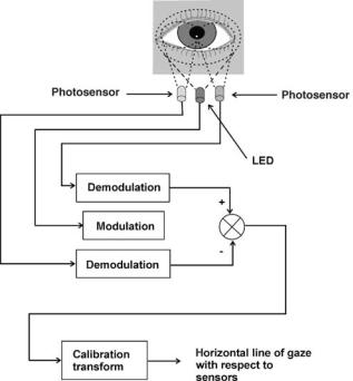
Figure 14. Schematic showing simple reflectivity pattern (limbus) tracker for horizontal measurement. (Adapted from a diagram in Ref. 8.)
horizontal position of the reflectivity pattern across the eye, with the most prominent feature of the pattern being the contrast between the white sclera and darker iris (limbus). Modulation of the LED, typically at 2 kHz or higher, and corresponding demodulation of photosensor signals diminishes the effect of ambient light. The signal is low pass filtered to remove modulation artifacts; and is either scaled and linearized with analog controls, or sampled and processed digitally, in order to scale and linearize the values.
Vertical position can be measured by orienting a similar LED and sensor array vertically, instead of horizontally. The results are less dependable because the high contrast iris to sclera boundary is often obscured by the eyelids. Alternately, vertical position is measured by aiming the horizontally oriented LED and sensor array at the boundary between the eye and the lower eyelid, and summing (instead of differencing) the photodetector signals. The result is really a measure of lower eyelid position, and takes advantage of the fact that the lower eyelid moves roughly in proportion to vertical eye motion. In either case, the vertical measurement is less accurate and less repeatable than the horizontal measure.
The LED and photosensors are positioned within 2 cm of the eye, and are mounted to a head band, goggles, or spectacle frames. The detector assembly inevitably obscures some of the visual field. Since the reflectivity pattern moves more or less as would a landmark on the eyeball surface, a 1 mm shift of the optics on the head is expected to produce an error of 58. There is often a distinct cross-talk effect. The horizontal measurement values are affected by vertical eye position, and visa versa.
EYE MOVEMENT, MEASUREMENT TECHNIQUES FOR |
277 |
If vertical eye position is also measured, the calibration transform can attempt to correct cross-talk.
System bandwidth is limited, primarily, by the low pass filtering needed due to the modulation scheme, and is typically 50–100 Hz. If the signal is processed digitally, sample rates are often at least 1000 Hz. It is possible to achieve resolutions of > 0.058 visual angle. While bandwidth and resolution are very good, accuracy is somewhat undependable because of headgear slippage affects, crosstalk effects, and, especially in the vertical axis, eye lid effects. Accuracy of 18 along a horizontal axis and 28 along a vertical axis may be achievable over a short period, but errors of several degrees would not be unusual, especially over longer periods or in the presence of vigorous head motion. Devices that use one LED and two photo sensors for a given axis tend to become very nonlinear, and difficult to calibrate over > 30 or 408 in either axis. The range can be extended somewhat by using multiple LEDs and sensors for each axis. Neither torsional eye movements, nor pupil diameter is measured.
Photoelectric, reflectivity pattern (limbus) trackers are best suited to measure dynamics of horizontal eye movements as opposed to point of regard measurement, although they are sometimes used for point of regard measurement as well. Systems in this category are commercially available from Applied Science Laboratories Bedford, MA (71), Cambridge Research Systems Ltd, UK (20), and Optomotor Laboratory, Freiburg, Germany (72).
Cambridge Research Systems offers a version of their device designed for use in fMRI environments. In this case, the LEDs and photodiodes are located outside of the magnet bore, and connected to the eye piece, within the magnet bore, via fiber optic cables (20).
Dual Purkinje Image Measurement (CR/4PI)
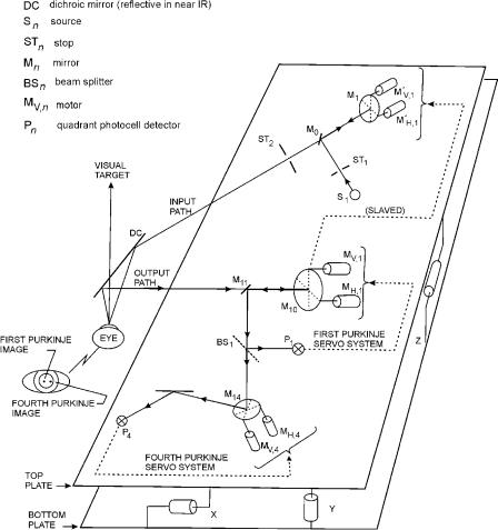
A technique was described by Cornsweet and Crane (45) and further developed by Crane and Steele (73,74) in which the eye is illuminated with a modulated IR source, and servo controlled mirrors are used to image the first and fourth Purkinje images onto solid state quadrant detectors. Demodulated, analog signals from the quadrant detectors are used, in separate feed back loops, to move the mirrors and keep the images centered on the detectors. The resulting mirror positions constitute measures of the feature positions, and can be used to compute eye rotation with respect to the optics.
A schematic representation of the system is shown in Fig. 15. The entire optics platform is mounted to a servo controlled XYZ stage, which automatically moves to optimize overall system alignment. A hot mirror beam splitter is used to direct light to and from the optical unit, which is positioned off to one side of the subject. By looking through the beam splitter, the subject has an unimpeded view of the forward visual field. Not shown in the simplified schematic is an autofocus mechanism, implemented with a beam splitter, off axis aperture, and bicell detector, in the first Purkinje image optical path.
The subject’s motion is usually restricted with a head rest or bite bar assembly. Because the fourth Purkinje image is visible only through the iris opening, measurement range is
278 EYE MOVEMENT, MEASUREMENT TECHNIQUES FOR
Figure 15. Schematic representation of Double Purkinje image eye tracker. (Redrawn from Ref. 73.)
restricted to about 108 visual angle, although this can be extended to about 158 by using drops to dilate the pupil. Accuracy is 1 min of arc, and the sampling rate is 1000 Hz. Using a model eye, Crane and Steele (74) empirically measured a bandwidth of 500 Hz (for small eye movements of several degrees), noise levels of 20 arc s rms, response delay of 0.25 ms, and linear tracking of slew rates up to 20008 s. The manufacturer of a current version of the device specifies a bandwidth of 400 Hz and a 1 ms response time (75).
Although the subject’s motion is restricted and the measurement range is small, the accuracy, precision and temporal bandwidth are exceptionally good. The Dual Purkinje image eye-tracking device can provide a precise enough and fast enough measurement, for example, to allow another device to effectively stabilize an image on the retina (74). Neither torsional eye movement nor pupil diameter is measured, but it is possible to attach an infrared optometer, which provides a real-time, analog measure of changes in eye accommodation (75). An updated version of the device described by Crane and Steele (74) is offered commercially by Fourward Technologies, Inc, Buena Vista, VA. (75).
Systems Using Two-Dimensional Video Sensor Arrays
Eye tracking devices that use 2D CCD or CMOS sensor arrays exist in wide variety, and are commercially available
from numerous sources. The term video oculography (VOG) is often used to describe this type of system. Most current systems in this category use the pupil to corneal reflection technique (CR/Pupil) to measure gaze direction, but there are exceptions. Some systems designed primarily to measure ocular torsion might rely on a fixed position of the head with respect to the sensor, and use only pupil position to correct for gaze direction changes. Some systems that normally use the pupil-to-corneal reflection technique have options to measure with only pupil position or only corneal reflection position under certain circumstances. Other systems are designed to measure the position of the head in space, and use a camera (or cameras) with a wide-angle view on which the corneal reflection can not easily be resolved. These systems may use the pupil position relative to a facial feature to compute gaze direction.
Note that a pupil-only or corneal-reflection-only measurement offers some advantages if it can be assured that the head does not move with respect to the camera. Pupil and corneal reflection motion have greater sensitivity to eye rotation than the pupil-to-corneal reflection vector, and the measurement is therefore more precise (less noisy).
Figure 16 is a functional diagram consistent with most current video-based eye tracking systems. The functions may be distributed among physical components in various ways, and a separate head tracking system may or may not be included.
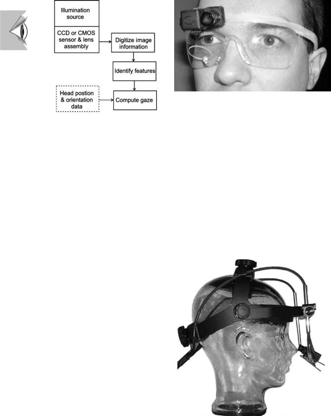
EYE MOVEMENT, MEASUREMENT TECHNIQUES FOR |
279 |
Figure 16. Schematic showing the basic functional architecture of most video-based eye tracking systems.
Some systems input video from the eye camera to PC memory via a USB or firewire connection, either directly from a camera with compatible output, or via a video– firewire converter. The PC CPU then does all the processing. Alternately, a frame grabber installed on the PC may be used to digitize a composite video signal. In some cases, the resulting digitized signal is processed by the PC, or in other cases, a frame grabber that also has image processing capabilities may do some portion of the processing before making a reduced information set available to the PC. In still other cases, the eye video is input to a completely custom processing board or board set, often populated with some combination of field programmable gate array (FPGA) and digital signal processing (DSP) components. The custom processor may do virtually all of the processing or may send a reduced data set to a PC. Other workstations may be used in place of the PCs referred to above. In short, there is enormous variety possible. Systems that support > 60 Hz update rates often make some use of custom processing components to help achieve the high speed. Although not yet capable of the same temporal bandwidth as several other types of system, camera based systems are now available with high enough update rates to make them useful for study of eye movement dynamics. Video-based systems almost always measure pupil diameter as a byproduct of computations for eye rotation measurement, and these systems are sometimes used as pupillometers.
The two main subcategories within this group are head mounted systems, having the sensor and small optics packages mounted to headgear; and remote systems, relying on optics mounted to the environment (table, instrument panel, etc.). In both cases these are often used as real time point of regard systems. The following sections describe video based, head mounted and remote eye tracking systems, respectively; followed by a section describing systems designed to handle the special problem of operation in MRI devices.
Head Mounted, Video Based Systems. Head mounted sensors are often designed to view a reflection of the eye from a beam splitter, as shown in Fig. 17, so that the
Figure 17. The head mounted module directly over the subject’s right eye contains both a camera and illuminator, which are aimed down at the tilted, hot mirror beam splitter. The camera views a reflection of the eye from the hot mirror. The module just to the nasal side of the eye camera module is a scene camera, aimed toward the subject’s field of view. (Courtesy of Applied Science Laboratories, Bedford, MA.)
sensor, lens, and illumination source need not be in the subject’s field of view. The beam splitter is coated to be a hot mirror, very reflective in the near-IR, but not in the visible spectrum. In some cases, however, the module containing the sensor is positioned on a stalk (Fig. 18), so that it can obtain a direct view of the eye. Illumination is most often provided by one or more near infrared LEDs. Both darkpupil and bright-pupil type optics are represented among available systems.
The image of the eye produced by a head mounted sensor yields information about eye orientation with respect to the head. In other words, line of gaze is measured in the head reference frame. In some cases, this is the
Figure 18. Head mounted camera and illuminator module is mounted on a stalk, and is aimed directly at the eye. (Courtesy of SR Research, Inc. Ontario.)
280 EYE MOVEMENT, MEASUREMENT TECHNIQUES FOR
desired quantity, but in other cases the desired measurement is point of gaze in the environment. In order to find point of gaze on objects in the environment, it is necessary either to detect the positions of those objects with respect to the head, or to detect the position and orientation of the head with respect to the environment containing the objects. Techniques for accomplishing this were discussed in the previous section titled ‘‘Measuring point of gaze in the presence of head motion’’. All of these methods have been used by commercially available, pupil–corneal reflectiontype systems.
Head tracking devices commonly used with head mounted eye trackers include magnetic systems that measure the position and orientation of a small, head gear mounted, set of coils with respect to a larger set of stationary coils; optical systems that use head mounted sensors to detect moving laser beams from a stationary source; and a system which uses a head mounted inertial package for high frequency measurements, corrected by lower frequency measurements from ultrasonic emitter–receiver pairs (8).
Head tracking systems capable of sufficient 6 degree of freedom accuracy usually restrict subject to 1 or 2 m of movement. Applications requiring a subject to walk or run a significant distance usually rely on a head mounted scene camera to capture information about point of gaze on the environment. There are available systems that allow subjects to move about with no physical connection to stationary components while either recording data on a recording device attached to the subject, or using wireless transmission to send data to a base station.
Systems intended for neurological testing are usually concerned with eye movement with respect to the head rather than point of gaze in the environment. Some of these systems measure ocular torsion as well as measuring gaze direction with either pupil-to-corneal-reflection or pupil position techniques.
Measurement accuracy, of head mounted, video-based, eye trackers, tends to be from 0.5–1.08 visual angle, with resolutions varying from 0.01 to 0.18 visual angle. Measurement range is 60–708 visual angle in the horizontal axis and usually 208 less in the vertical axis due to eye lid interference. These figures refer to measurement of gaze direction with respect to the head. The measurable field of view with respect to the environment is unrestricted because subjects are free to turn their heads and bodies. Measurement update rates range from 25 to 360 Hz, with at least one commercially available system offering 500 Hz with pupil-only (as opposed to pupil-to-corneal-reflection) measurements.
When a head mounted eye tracker is used in combination with a head tracking device, in order to measure point of gaze in the environment, error in the final measurement is increased due to noise and error in the head position and orientation measurement. The result can vary widely depending on the particular combination of equipment being used and the conditions under which measurements are being made. It is probably not unreasonable to expect additional errors corresponding to 0.2–1.08 visual when using a head mounted eye tracker to measure point of gaze on elements in the environment. Conditions that create
difficulties for either the eye or head tracking components, for example a heavily metallic environment when using a magnetic head tracker, or occlusion of the pupil image by reflection from some external light source, may cause errors to increase dramatically or make the measurement impossible.
Manufacturers of systems that include ocular torsion measurement usually specify torsion measurement range of 18–208, resolution of 0.18, and linearity between 1 and 4% of full scale. Video-based, head mounted systems, using the pupil to corneal reflection measurement technique, currently allow point of gaze measurement in the most diverse environments, and with the greatest freedom of subject motion and measurable field of view. They do not have as high a temporal bandwidth as scleral search coil, double Purkinje image, EOG, or reflectivity (limbus) tracking systems, and are not as accurate or precise as scleral search coil, or double Purkinje image systems. They do require that the subject wear head gear, but the size and obtrusiveness of the headgear has been steadily reduced over the past decade. It is becoming practical to use this type of system in ever more flexible and varied settings. The amount and severity of subject motion, the amount of variation in ambient light environment, and the length of time over which continuous measurements must be made, all tend to trade off somewhat against the accuracy and dependability of the measurements.
Video-based eye trackers, with head mounted optics, are offered commercially by: Alphabio, France (76); Applied Science Laboratories, Bedford, MA (71); Arrington Research, Inc., Scottsdale, AZ (77); Chronos Vision GmbH, Berlin, Germany (78); Guymark UK Ltd, UK (22); EL-MAR Inc, Downsview, ON (79); ISCAN, Inc., Burlington, MA (80); Neuro Kinetics Inc. Pittsburgh, PA (24); SensoMotoric Insturments GmbH, Berlin, Germany (81); and SR Research Ltd, Osgoode, ON (82).
Head mounted systems that measure ocular torsion are available from: Alphabio, France (72); Arrington Research, Inc, Scottsdale, AZ (77); Chronos Vision GmbH, Berlin, Germany (78); Neuro Kinetics Inc. Pittsburgh, PA (24); and SensoMotoric Insturments GmbH, Berlin, Germany (81).
Remote, Video-Based Systems. Remote (nonhead mounted) systems have one or more videosensors and illumination sources that are fixed to the environment and aimed toward the subject. The optics may sit on a table next to or underneath a monitor being viewed by the subject, may be mounted on a vehicle (or vehicle simulator) instrument panel, or mounted to the environment in some other way. Both bright and dark pupil optics are used. In the case of bright pupil optics, the illuminator may be a ring of LEDs placed close enough to the lens to produce the bright pupil effect, an LED actually mounted over the front of the lens so that it blocks only a small portion of the lens surface, or a beam splitter arrangement like that shown in Fig. 6.
Some system configurations require the subject’s head to be stabilized. This maximizes achievable accuracy and dependability. A chin and forehead rest, or cheek and forehead rest are commonly used, although these do allow
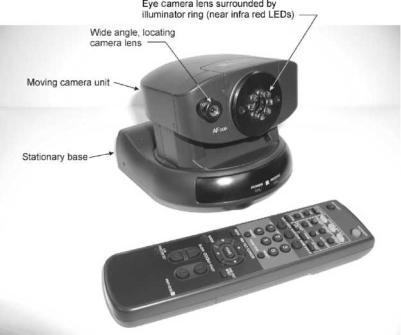
a small amount of head motion. A bite bar with a dental impression can be used to completely stabilize the head. In the case of nonhuman primate research the head is often stabilized by other means appropriate for neural recording. The camera, lens, and illumination sources can all be stationary (after manual positioning) and may safely be designed with a field of view just large enough to comfortably accommodate pupil and corneal reflection motion due to eye rotation. If the subject’s head is sufficiently stabilized there is no need to differentiate between eye rotation and head translation, and, as previously discussed, there is a precision advantage to using a pupil-only (rather than pupil-to-corneal-reflection) measurement. Some systems allow a choice between pupil-to-corneal-reflection and pupil-only or corneal-reflection-only measurement.
Alternately, the eye camera field of view may be wide enough to accommodate the motions of a seated subject who is not restrained, but is voluntarily remaining still. If the subjects are provided with feedback, so that they know when they are moving out of the legal space, it is only necessary to allow 5 cm of head motion.
Many remote systems are designed to allow enough head motion to accommodate normal motions of a person working at a computer terminal or driving a car, and so on. This is accomplished either by dynamically rotating the camera optical axis so that it always points toward the eye being tracked, by using a camera field of view wide enough to accommodate the desired head motion, using multiple cameras, or some combination of these. Head motion toward and away from the eye camera must either be small enough to remain within the lens system depth-of-field, or must be accommodated by an autofocus mechanism. Figure 19 shows an example of an eye camera that automatically moves in azimuth (pan) and elevation (tilt) to follow the eye as the head moves about. Figure 20 is an example of a camera with a moving mirror used to direct
EYE MOVEMENT, MEASUREMENT TECHNIQUES FOR |
281 |
the optical path, and Fig. 21 shows a system with stationary sensor and illumination components in an enclosure.
Systems with a moving camera or moving mirrors often use a closed loop control, based on the detected position of the pupil in the camera field of view. The moving element is driven to move the image toward center. If the pupil is completely lost from the camera field of view, the system may execute a search pattern, use information from a separate head tracking system to reacquire the eye, or require that a human operator intervene to reacquire the eye image. Such systems can have a relatively narrow eye camera field of view, thus maximizing image resolution for the features of interest. The disadvantage is the need for moving parts, and the possibility of failing to maintain the eye image in the camera field of view.
Systems that do not require moving parts have a significant advantage in terms of system simplicity and dependability. Furthermore, there is the possibility of using the same image to measure head position and to track the movement of both eyes. The trade-off is that as the field of view is increased, resolution is reduced (the pupil and corneal reflection are imaged onto fewer pixels) and the features of interest must be identified within a larger, more complex image.
The pupil-to-corneal-reflection method alone can be used to determine gaze angle with respect to the eye camera. However, in the presence of significant head motion, this is not sufficient to accurately determine point of gaze on other surfaces. Some remote systems use head trackers to find the position of the eye in space, and use the information to more accurately compute point of gaze on other stationary surfaces. Head position information can also be used to help aim moving cameras or mirrors. The same types of head tracker mentioned in the previous section, as being appropriate for use with head mounted eye trackers, are sometimes used in conjunction with remote eye trackers.
Figure 19. Example of a remote eye tracker optics module that moves in azimuth (pan) and elevation (tilt) to keep a telephoto eye image within the camera field of view. (Courtesy of Applied Science Laboratories, Bedford, MA.)
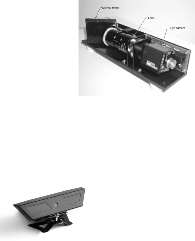
282 EYE MOVEMENT, MEASUREMENT TECHNIQUES FOR
Figure 20. Example of a remote eye tracker optics module that uses a moving mirror to keep a telephoto eye image within the camera field of view. The optics module is shown with its cover removed. (Courtesy of Applied Science Laboratories, Bedford, MA.)
In the case of remote eye trackers, it is also possible to use one or more wide angle cameras to locate the head and eyes. The head tracking camera (or cameras) may be separate from the eye tracking camera, or alternately, the same cameras (or cameras) may be used for both.
At present, remote systems that offer > 60 Hz update rates either require the head to be stabilized, or use a narrow field image that is dynamically directed to follow head motions. Systems that use stationary wide-angle optics typically update at 60 Hz or less, probably because of the extra processing required for feature recognition in the more complex wide-angle image. Systems that either require the head to be stabilized or direct a narrow field of camera to follow head motion are available with update rates of up to 360 Hz. As with head mounted systems, higher update rates result in lower signal/noise ratios for the sensor.
Figure 21. Example of a remote eye tracker optics module using stationary wide angle optics. Sensor, lens, and illumination components are within the enclosure. (Courtesy of Tobii Tehnology AB, Stockholm, Sweden.)
For configurations that stabilize the subject’s head, accuracy of remote, video-based eye tracking systems tends to be 0.5–1.08 visual angle, with resolutions varying from 0.01 to 0.18 visual angle. When a remote eye tracker is used to measure point of gaze on a stationary surface, and head motion is allowed, some additional error can be expected. If no attempt is made to account for head motion, the equation in Fig. 11 can be used to estimate the amount of error expected from a given change in head position. If an attempt is made to correct for head movement, the amount of additional error depends on the accuracy of the head position measurements, and the way the information is used in the point-of-gain computation, as well as the range of head motion. It is probably not unreasonable to expect an additional 0.5–1.58 of error when there is significant head motion. Data may also have additional error, or even be briefly lost, during fast head motion, due to instability of the eye image on the eye-camera field of view.
Remote systems using one eye-camera and one illumination source, and the pupil-to-corneal-reflection method, can generally measure gaze directions that are within 25–358 visual angle from the eye-camera lens. At more eccentric angles the corneal reflection is either not visible to the eye camera, or easily confused with multiple reflections from the sclera. The exception is that when line of gaze is below the eye-camera, the upper eyelid often begins to occlude part of the pupil. The amount of eye lid occlusion under this condition varies from subject to subject. Furthermore, different eye tracking systems, using different recognition and center computation algorithms, are tolerant of different amounts of occlusion. This often limits measurement range to 5–108 visual angle below the eyecamera, and for this reason, the environment is usually arranged with the eye-camera at the bottom of the scene space that is of interest. The result is a horizontal gaze measurement range of 50–708 visual angle, and a vertical range of 35–458.
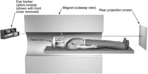
The range of measurable gaze directions, using the pupil-to-corneal-reflection method, can be increased by using multiple illumination sources (and thus multiple corneal reflections). The horizontal range can be increased to as much as 908 by widely spacing illumination sources. Only a more modest range expansion is possible in the vertical axis because of eyelid interference.
Remote, video-based, eye trackers, offer the possibility of measuring eye movement very unobtrusively. Unlike head mounted systems, nothing need be worn by the subject (unless using a type of head tracker that requires a head mounted sensor), and the optics can be hidden from obvious view by a filter that is transmissive in the near-IR. The range of subject motion and measurable field of view is significantly more restricted than for systems with head mounted optics, although less so than for most other techniques. Measurement accuracy, resolution, and temporal bandwidth are not as good as that available with the much more restrictive and obtrusive double Purkinje image method, or scleral search coil method.
Remote, video-based, eye movement measurement systems are commercially available from: Applied Science Laboratories, Bedford, MA (71); Arrington Research, Inc., Scottsdale, AZ (77); Cambridge Research Systems Ltd, UK (20), ISCAN, Inc., Burlington, MA (80); LC Technologies Inc., Fairfax, VA (83); Metrovision, Pe´renchies, France (23), Seeing Machines, Canberra, Australia (84); SensoMotoric Insturments GmbH, Berlin, Germany (81); SR Research Ltd, Osgoode, ON (82); and Tobii Technology AB, Stokholm, Sweeden (85).
Video-Based Systems for use in Conjunction with f MRI.
There are commercially available, video-based eye tracker systems, which use the pupil-to-corneal-reflection method, and are specifically configured to be used in conjunction with fMRI measurements of brain activity.
During fMRI measurements, the subject’s head and torso are inside the main MRI magnet bore, and a smaller head coil is placed fairly closely around the subject’s head. The head coil always has an opening over the subject’s eyes, and there is usually some provision for the subject to look at a visual display, often with the help of a mirror or set of mirrors. The environment is challenging because there is
EYE MOVEMENT, MEASUREMENT TECHNIQUES FOR |
283 |
Figure 22. Example of eye tracker optical path in an fMRI system. The drawing shows the magnet in cutaway view. One mirror, just above the subject’s face, reflects the eye image to the eye tracker camera, while another allows the subject to view a stimulus on a rear projection screen. Many variations to this arrangement are used, including configurations in which both the projection screen and eye tracker optics module are at the same end of the magnet. (Courtesy of Applied Science Laboratories, Bedford, MA.)
not much room in which to arrange an optical path from the subject’s eye to a camera, and also because any electronic equipment used must operate in a high magnetic field, without creating even small amounts of magnetic field noise that would interfere with the MRI measurement.
One approach is to use a camera equipped with a telephoto lens, and placed outside of the magnet. The camera is aimed down the magnet bore, and views a reflection of the eye on a small mirror placed inside of the magnet, near the subject’s head. The optical path length from the camera lens to the eye is typically at least 2.5–3 m, necessitating a fairly large telephoto lens, and powerful illumination source. An example is shown in Fig. 22, and is similar to a setup described by Gitleman et al. (86). The system shown is using a bright pupil technique, so there is only one coaxial path for both the camera and illumination beam. In this case, a second mirror allows the subject to look at a display screen. Many variations of both the eye camera and display screen optical paths are possible.
Other systems bring the eye image out of the magnet, to the sensor, with a coherent, fiber optic bundle. This has the advantage of not requiring large, telephoto optics, but the resolution of fiber bundles are limited and light is attenuated somewhat unevenly by the individual fibers that comprise the bundle. Fiber optics may also be used to relay the output from an illumination source into the magnet. It is possible to place a small camera inside the magnet, but it can be difficult to avoid some interference with the magnetic field and resulting degradation of the fMRI measurement.
Video-based, eye tracking systems designed for use during fMRI measurement, are commercially available from Applied Science Laboratories, Bedford, MA (71); Arrington Research, Inc., Scottsdale, AZ (77); ISCAN, Inc., Burlington, MA (80); and SensoMotoric Insturments GmbH, Berlin, Germany (81).
COMPARISON OF EYE MOVEMENT MEASUREMENT TECHNIQUES
Table 1 is an abbreviated comparison of the various techniques discussed.

284 |
EYE MOVEMENT, MEASUREMENT TECHNIQUES FOR |
|
|
||
Table 1. Summary of Most Prevalent Eye Tracking Techniquesa |
|
|
|||
|
|
|
|
Typical |
|
|
|
|
|
Reference |
Typical |
Method |
|
Typical Applications |
Typical Attributes |
Frame(s) |
Performance |
|
|
|
|
|
|
EOG |
|
Dynamics of saccades |
High bandwidth |
head |
static accuracy: 3-78 |
|
|
smooth pursuit |
Eyes can be closed |
|
resolution: with low pass |
|
|
nystagmus |
In expensive |
|
filtering and periodic |
|
|
|
Drift problem (poor position |
|
rezero, virtually infinite |
|
|
|
accuracy) |
|
bandwidth: 100 Hz |
|
|
|
Requires skin electrodes - |
|
|
|
|
|
otherwise unobtrusive |
|
accuracy: 0.28 |
Scleral Coil |
Dynamics of saccades, |
Very high accuracy and |
Room |
||
|
|
smooth pursuit, |
precision |
|
resolution: 1 arc min. |
|
|
nystagmus |
Invasive |
|
range: 308 |
|
|
Miniature eye movements |
Very obtrusive |
|
bandwidth: 200 Hz |
|
|
Point of gaze |
High bandwidth |
|
|
|
|
Scan path |
|
|
|
|
|
Torsion |
|
|
|
Limbus |
|
Dynamics of saccades, |
High bandwidth |
head gear |
accuracy: varies |
(using small |
smooth pursuit, |
Inexpensive |
|
resolution: 0.18 (much |
|
number of |
nystagmus |
Poor vertical accuracy |
|
better res. possible) |
|
photo |
|
Point of gaze |
Obtrusive (sensors close to eye) |
|
range: 308 |
sensors) |
Scan path |
Head gear slip errors |
|
update rate: 1000 |
|
|
|
|
|
|
samples/s |
CR/Pupil |
|
Point of gaze |
Minimal head gear slip error |
Head gear |
accuracy: 18 |
|
|
Line of gaze |
Unobtrusive |
Room |
resolution: 0.28 hor. |
|
|
Scan path |
Low to medium |
Cockpit |
range: 508 |
|
|
Dynamics of eye |
bandwidth |
|
vert. range: 408 |
|
|
movements (only with |
Problems with sunlight |
|
update rate: 50 or 60 |
|
|
subset of systems offering |
Wide variety of configurations |
|
samples/s. |
|
|
high update rates) |
and environments |
|
Update rates up to 360 |
|
|
Torsion (available only |
|
|
samples/s available on |
|
|
on some systems) |
|
|
some systems (higher for |
|
|
|
|
|
pupil only measurement); |
CR/4PI |
|
Dynamics of saccades, |
Very high accuracy and precision |
Room |
accuracy: 1 arc min. |
|
|
smooth pursuit, |
High bandwidth |
|
resolution: < 1 arc min |
|
|
nystagmus |
Obtrusive (large optics package, |
|
range: 208 |
|
|
Miniature eye movements |
restricted head motion) |
|
bandwidth: 400 Hz |
|
|
Point of gaze |
Limited range |
|
|
|
|
Scan path |
|
|
|
|
|
Image stabilization on |
|
|
|
retina Accommodation
aAdapted from Ref. 8.
An earlier, but comprehensive and still pertinent review of eye movement measurement techniques, can be found in Young and Sheena (87). A book by Duchowski (53) presents a detailed treatment of many aspects of eye tracking methodology. The journal Computer Vision and Image Understanding has devoted an entire special edition to developments in optical eye tracking, with an emphasis on real-time, nonintrusive techniques (88). A database of commercially available eye movement measurement equipment is available at a web site hosted by the University of Derby (89).
BIBLIOGRAPHY
Cited References
1.Roth EM, Finkelstein S. Light environment. In: Roth EM, editor. Compendium of Human responses to the Aerospace Environment. NASA CR-1205(1); 1968.
2.Westheimer G. The eye, In: Mountcastle VB, editor, Medical Physiology, Volume One. Saint Louis: The C. V. Mosby Co.; 1974.
3.Fry GA, Hill WW. The center of rotation of the eye. Am J Optom Arch Am Acad Optom 1962;390:581–595.
4.Wyatt HJ. The form of the human pupil. Vision Res 1995;35(14):2021–2036.
5.Haslwanter T. Mathematics of three-dimensional eye rotations. Vision Res 1995;35:1727–1739.
6.Hallett P. Eye movements. In: Boff KR, Kaufman L, Thomas JP, editors. Handbook of Perception and Human Performance. New York: John Wiley & Sons, Inc.; 1986.
7.Robinson DA. A method of measuring eye movement using a scleral search coil in a magnetic field, IEEE Transactions on Bio-Medical Electronics 1963;BMI-10:137–145.
8.Leger A et al. Alternative Control Technologies, North Atlantic Treaty Organization, RTO-TR-7, 1998.
9.Collewijn F, van der Marx S, Jansen TC. Precise recording
of human eye movements. Vision Res 1975;15:447– 450.
10.Judge SJ, Richmond BJ, Chu FC. Implantation of magnetic search coils for measurement of eye position: an improved method. Vision Res 1980;20:535–538.
11.Skalar Medical BV. (2002, December 20). Home. (Online). Available at http://www.skalar.nl, Accessed Feb. 9, 2005.
12.Riverbend Instruments. (No date). Home. (Online). Available at http://www.riverbendinst.com/index.htm. Accessed 13 April 2005.
13.Mowrer OH, Ruch RC, Miller NE. The corneo-retinal potential difference as the basis of the galvanometric method of recording eye movements. Am J Physiol 1936;114:423.
14.Marg E. Development of electro-oculography—standing potential of the eye in registration of eye movement. AMA Arch Ophthalmol 1951;45:169.
15.Kris C. Vision: electro-oculography. Glasser O, editor. Medical Physics: Chicago: Chicago Yearbook Publishers; 1960.
16.Shackel B. Review of the past and present in oculography. Medical Electronics Proceedings of the Second International Conference. London: Hiffe; 57, 1960.
17.Shackel B. Eye movement recording by electro-oculography. In: Venables PH, Martion I, editors, A manual of Psychophysiological Methods. Amsterdam: North-Holland Publishing Co.; pp 300–334, 1967.
18.Arden GB, Barrada A, Kelsey JH. New clinical test of retinal function based upon the standing potential of the eye. Br J Ophthalmol 1962;46:467.
19.De Rouck A, Kayembe D. A clinical procedure of the simultaneous recording of fast and slow EOG oscillations. Int Ophthalmol 1981;3:179–189.
20.Cambridge Research Systems. (2005, February 9). Home. (Online). Available at http://www.crsltd.com Accessed 2005, Feb. 10.
21.GN Otometrics. (2004). Products. (Online). Available at http://www.gnotometrics.com/products.htm. Accessed 2005 Feb. 9.
22.Guymark UK Ltd. (No date). Vestibular Assessment. (Online). Available at http://www.guymark.com/vestibul.html. Accessed 2005, Feb. 9.
23.Metrovision. (No date). Homepage (Online). Available at http://www.metrovision.fr. Accessed 2005, Feb. 9.
24.Neuro Kinetics Inc. (No date). Products and Services. (Online). Available at http://neuro-kinetics.com/products- research.htm. Accessed 2005, Feb. 9.
25.Nguyen K, Wagner C, Koons D, Flickner M. Differences in the infrared bright pupil response of human eyes. Proceedings ETRA 2002 Eye Tracking Research & Applications Symposium. New Orleans: March 25–27, 2002.
26.Borah J. Helmet Mounted EyeTtracking for Virtual Panoramic Display Systems–Volume I: Review of Current Eye Movement Measurement Technology. US Air Force report AAMRL-TR-89019, 1989.
27.Zhu S, Moore T, Raphan T. Robust pupil center detection using a curvature algorithm. Computer Methods Programs Biomed 1999;59:145–157.
28.Mulligan JB. A software-based eye tracking system for the study of air-traffic displays. Proceedings ETRA 2002 Eye Tracking Research & Applications Symposium. New Orleans: March 25–27, 2002.
29.Ohno T, Mukawa N, Yoshikawa A. FreeGaze: a gaze tracking system for everyday gaze interaction. Proceedings ETRA 2002 Eye Tracking Research & Applications Symposium. New Orleans: March 25–27, 2002.
30.Charlier J et al. Real time pattern recognition and feature analysis from video signals applied to eye movement and pupillary reflex monitoring. Proceedings of the 6th Int Visual Field Symposium. In: Heijl A, Greve EL, editors. Dordrecht, The Netheralands: Dr. W Junk Publisheres; 1985.
EYE MOVEMENT, MEASUREMENT TECHNIQUES FOR |
285 |
31.Sheena D. Pattern-recognition techniques for extraction of features of the eye from a conventional television scan. In: Monty RA, Senders JW, editors. Eye Movements and Psychological Processes. Hillsdale (NJ): Lawrence Erlbaum; 1976.
32.U.S. Pat. 5,302,819 1994. Kassies M. Method of and Apparatus for, Detecting an Object.
33.Zhai S, Morimoto C, Ihde S. Manual and Ggaze input cascaded (MAGIC) pointing. Proceedings CHI’99: ACM Conference on Human Factors in Computing Systems. Pittsburgh: ACM: 246–253, 1999.
34.Tomono I, Muneo X, Lobayashi Y. A TV camera system that extracts feature points for non-contact eye movement detection. iSPIE vol. 1194 Optics, Illumination, and Image Sensing for Machine Vision IV; 1989.
35.Ebisawa Y, Satoh S. Effectiveness of pupil area detection technique using two light sources and image difference method. 15th Annual International Conference of the IEEE Engineering in Medicine and Biology Society. San Diego: 1993.
36.Eizenman M, Frecker RC, Hallett PE. Precise non-contacting measurement of eye movements using the corneal reflex. Vision Res 1984;24:167–174.
37.Xiao J, Baker S, Matthews I, Kanade T. Real-Time Combined 2D+3D Active Appearance Models. Proceedings of the IEEE Conference on Computer Vision and Pattern Recognition. June, 2004.
38.Matthew X, Baker S. (none) Real-Time AAM fitting algorithms. [Online]. Carnegie Mellon University. Available at http:// www.ri.cmu.edu/projects/project_448.html. Accessed 9 Feb. 2005.
39.Cootes TF, Edwards GJ, Taylor CJ. Active appearance models. IEEE Transactions on Pattern Analysis and Machine Intelligence 2001;23:681–685.
40.Zhu J, Yang J. Subpixel Eye-Gaze Tracking. Proceedings of the fifth IEEE International Conference on Face and Gesture Recognition 2002; 131–136.
41.U.S. Pat. 5,818,954 1998. Tomono M, Iida K, Ohmura X. Method of Detecting Eye Fixation using Image Processing.
42.Merchant J, Morrissette R, Perterfield JI. Remote measurement of eye direction allowing subject motion over one cubic foot of space. IEEE Transactions on Biomedical Engineering 1974; BME-21:309–317.
43.Sheena D, Borah J. Compensation for some second order effects to improve eye position measurements. In: Fisher DF, Monty RA, Senders JW, editors. Eye Movements: Cognition and Visual Perception. Hillsdale (NJ): Lawrence Erlbaum Associates; 1981.
44.U.S. Pat. 6,5987,971, 2003. Cleveland D. Method and System for Accommodating Pupil Non-concentricity in Eyetracker Systems.
45.Cornsweet TN, Crane HD. Accurate two-dimensional eye tracker using first and fourth Purkinje images. J Opt Soc Am 1973;63:921.
46.Torok N, Guillemin B, Barnothy JM. Photoelectric nystagmography. Ann Otol Rhinol Laryngol 1951;60:917.
47.Smith WM, Warter PJ. Eye movement and stimulus movement: New Photoelectric electromechanical system for recording and measuring tracking motions of the eye. J Opt Soc Am 1960;50:245.
48.Stark L, Sandberg A. A simple instrument for measuring eye movements, Quarterly Progresss Report 62, Research Laboratory of Electronics, Massachusetts Insstitute of Technology; 1961. p. 268.
49.Wheeless LL, Boynton RM, Cohen GH. Eye movement responses to step and pulse-step stimuli. J Opt Soc Am 1966;56:956–960.
286EYE MOVEMENT, MEASUREMENT TECHNIQUES FOR
50.Young LR. Recording eye position. In: Clynes M, Milsum JH, editors. Biomedical Engineering Systems. New York: McGraw-Hill; 1970.
51.Findlay JM. A simple apparatus for recording micorsaccades during visual fixation. Quart J Exper Psychol 1974;26:167– 170.
52.Reulen JP et al. Precise recording of eye movement: the IRIS technique. part 1. Med Biol Eng Comput 1988;26:20–26.
53.Duchowski AT. Eye Tracking Methodology Theory and Practice. London: Springer-Verlag; 2003.
54.U.S. Pat. 4,852,988, 1989. Velez J, Borah J. Visor and camera providing a parallax-free field-of-view image for a headmounted eye movement measurement system.
55.Edelman ER. Video based monitoring of torsional eye movements. S.M. dissertation, Massachusetts Institute of Technology, Cambridge (MA). 1979.
56.Proceedings of the 3rd VOG workshop, Tubingen, Germany, Nov. 30–Dec. 2, 1999.
57.Hatamian M, Anderson DJ. Design considerations for a realtime ocular counterroll instrument. IEEE Trans Biomed Eng 1983;30:278–288.
58.Clarke AH, Teiwes W, Scherer H. Videooculography—an alternative method for measurement of three-dimensional eye movements. In: Schmid R, Zambarbieri D, editors. Oculomotor Control and Cognitive Processes, Amsterdam: Elsevier; 1991.
59.Bucher U, Heitger F, Mast F. A novel automatic procedure for measuring ocular counterrolling. Behav Res Methods Instr Comp 1990;22:433–439.
60.Moore ST, Haslwanter T. Curthoys IS, Smith ST. A geometric basis for measurement of three-dimensional eye poisition using image processing. Vision Res 1996;36: 445–459.
61.Petrka RJ, Merfeld DM. Calibration techniques for videooculography, Poster Presentation at Barany Society Meeting. Sydney Australia; 1996.
62.Groen E, Nacken PFM, Bos JE, De Graaf B. Determination of ocular torsion by means of automatic pattern recognition. IEEE Trans Biomed Eng 1996;43(5): 471–479.
63.Zhu D, Moore ST, Raphan T. Teal-time torsional eye position calculation from video images. Soc Neurosci Abstr 1999;25:1650.
64.Guillemant P, Ulmer E, Freyss G. 3-D eye movement measurements on four Comex’s drivers using video CCD cameras, during high pressure diving. Acta Otolaryngol (Suppl) (Stockh) 1995;520:288–292.
65.McConkie GW. Evaluating and reporting data quality in eye movement research. Behav Res Methods Instrum 1981;13: 97–106.
66.Kliegle R, Olson RK. reduction and calibration of eye monitor data. Behav Res Methods Instrum 1981;13:107– 111.
67.Jacob RK. Eye tracking in advanced interface design. In: Barfield W, Furness T, editors. Virtual Environments and Advanced Interface Design. New York: Oxford University Press; 1995.
68.U.S. Pat. 6,578,962, 2003. Amir MD, Flickner DB, Koons X, Russell GR. (to Calibration-Free Eye Gaze Tracking).
69.American Conference of Governmental Industrial Hygienists, 2001 TLVs and BEIs, ACGIH, 1330 Kemper Meadow Drive, Cincinnati, OH; 2001.
70.Sliney DH, Wolbarsht M. Safety with Lasers and Other Optical Sources: A Comprehensive Handbook. New York: Plenum Press; 1980.
71.U. S. Pat. (to Applied Science Laboratories). (2005, January
5)Home. (Online). Available at http:http://www.a-s-l.com. Accessed 9 Feb. 2005.
72.U. S. Pat. (to Applied Science Laboratories). (No date). Express Eye. (Online), Available at http://www.optom.de/ english/exe. htm. Accessed 9 Feb. 2005.
73.Crane HD, Steele CM. Accurate three-dimensional eyetracker. Appl Opt 1978;17:691.
74.Crane HD, Steele CM. Generation-V dual-Purkinje image eyetracker. Appl Opt 1985;24:527–537.
75.Fourward Technologies Inc. (2004, November 11). Home (Online). Available at http://www.fourward.com. Accessed 9 Feb. 2005.
76.Alphabio. (No date). Home. (Online). Available at http:// www.electronica.fr/alphabio. Accessed 9 Feb. 2005.
77.Arrington Research, Inc. (2004, September 9). Home. (Online). Available at http://www.arringtonresearch.com. Accessed 9 Feb. 2005.
78.Chronos Vision. (no date). Eye Tracking. (Online). Available at http://www.chronos-vision.de/eyetracking/default_start_ eyetracking.htm. Accessed 9 Feb. 2005.
79.EL-MAR, Inc. (No date). Menu. (Online). Available at http:// www.interlog.com/ elmarinc/menu.htm. Accessed 9 Feb. 2005.
80.ISCAN Inc., (no date). Home. (Online). Available at http:// iscaninc.com. Accessed 9 Feb. 2005.
81.SensoMotoric Instruments. (No date). Home. (Online). Available at http://www.smi.de. Accessed 9 Feb. 2005.
82.SR Research Ltd. (2004, Nov. 24). Home. (Online). Available at http://www.eyelinkinfo.com/. Accessed 9 Feb. 2005.
83.LC Technologies Inc. (2003)., Home. (Online). Available at http://www.eyegaze.com. Accessed 9 Feb. 2005.
84.Seeing Machines. (2004). Home. (Online). Available at http:// www.seeingmachines.com. Accessed 9 Feb. 2005.
85.Tobii Technology. (2005). Home. (Online). Available at http:// www.tobii.se. Accessed 9 Feb. 2005.
86.Gitelman DR, Parrixh TB, LaBar KS, Mesulam MM. Realtime monitoring of eye movements using infrared videooculography during functional magnetic resonance imaging of the frontal eye fields. NeuroImage 2000;11:58–65.
87.Young LR, Sheena D. Survey of eye movement recording methods. Behav Res Methods Instrumen 1975;7:397– 429.
88.Wechsler H, Duchowski A, Flickner M. Editorial, special issue: eye detection and tracking. Computer Vision Image Understanding 2005;98:1–3.
89.Eye Movement Equipment Data Base (EMED). (2002, May 2). Home. (Online). Available at http://ibs.derby.ac.uk/emed. Accessed 9 Feb. 2005.
See also ELECTRORETINOGRAPHY; FIBER OPTICS IN MEDICINE; OCULAR MOTILITY RECORDING AND NYSTAGMUS.