

- •VOLUME 3
- •CONTRIBUTOR LIST
- •PREFACE
- •LIST OF ARTICLES
- •ABBREVIATIONS AND ACRONYMS
- •CONVERSION FACTORS AND UNIT SYMBOLS
- •EDUCATION, COMPUTERS IN.
- •ELECTROANALGESIA, SYSTEMIC
- •ELECTROCARDIOGRAPHY, COMPUTERS IN
- •ELECTROCONVULSIVE THERAPHY
- •ELECTRODES.
- •ELECTROENCEPHALOGRAPHY
- •ELECTROGASTROGRAM
- •ELECTROMAGNETIC FLOWMETER.
- •ELECTROMYOGRAPHY
- •ELECTRON MICROSCOPY.
- •ELECTRONEUROGRAPHY
- •ELECTROPHORESIS
- •ELECTROPHYSIOLOGY
- •ELECTRORETINOGRAPHY
- •ELECTROSHOCK THERAPY.
- •ELECTROSTIMULATION OF SPINAL CORD.
- •ELECTROSURGICAL UNIT (ESU)
- •EMERGENCY MEDICAL CARE.
- •ENDOSCOPES
- •ENGINEERED TISSUE
- •ENVIRONMENTAL CONTROL
- •EQUIPMENT ACQUISITION
- •EQUIPMENT MAINTENANCE, BIOMEDICAL
- •ERGONOMICS.
- •ESOPHAGEAL MANOMETRY
- •EVENT-RELATED POTENTIALS.
- •EVOKED POTENTIALS
- •EXERCISE FITNESS, BIOMECHANICS OF.
- •EXERCISE, THERAPEUTIC.
- •EXERCISE STRESS TESTING
- •EYE MOVEMENT, MEASUREMENT TECHNIQUES FOR
- •FETAL MONITORING
- •FETAL SURGERY.
- •FEVER THERAPY.
- •FIBER OPTICS IN MEDICINE
- •FICK TECHNIQUE.
- •FITNESS TECHNOLOGY.
- •FIXATION OF ORTHOPEDIC PROSTHESES.
- •FLAME ATOMIC EMISSON SPECTROMETRY AND ATOMIC ABSORPTION SPECTROMETRY
- •FLAME PHOTOMETRY.
- •FLOWMETERS
- •FLOWMETERS, RESPIRATORY.
- •FLUORESCENCE MEASUREMENTS
- •FLUORESCENCE MICROSCOPY.
- •FLUORESCENCE SPECTROSCOPY.
- •FLUORIMETRY.
- •FRACTURE, ELECTRICAL TREATMENT OF.
- •FUNCTIONAL ELECTRICAL STIMULATION
- •GAMMA CAMERA.
- •GAMMA KNIFE
- •GAS AND VACUUM SYSTEMS, CENTRALLY PIPED MEDICAL
- •GAS EXCHANGE.
- •GASTROINTESTINAL HEMORRHAGE
- •GEL FILTRATION CHROMATOGRAPHY.
- •GLUCOSE SENSORS
- •HBO THERAPY.
- •HEARING IMPAIRMENT.
- •HEART RATE, FETAL, MONITORING OF.
- •HEART VALVE PROSTHESES
- •HEART VALVE PROSTHESES, IN VITRO FLOW DYNAMICS OF
- •HEART VALVES, PROSTHETIC
- •HEART VIBRATION.
- •HEART, ARTIFICIAL
- •HEART–LUNG MACHINES
- •HEAT AND COLD, THERAPEUTIC
- •HEAVY ION RADIOTHERAPY.
- •HEMODYNAMICS
- •HEMODYNAMIC MONITORING.
- •HIGH FREQUENCY VENTILATION
- •HIP JOINTS, ARTIFICIAL
- •HIP REPLACEMENT, TOTAL.
- •HOLTER MONITORING.
- •HOME HEALTH CARE DEVICES
- •HOSPITAL SAFETY PROGRAM.
- •HUMAN FACTORS IN MEDICAL DEVICES
- •HUMAN SPINE, BIOMECHANICS OF
18.Garfield RE, Maner WL, Maul H, Saade GR. Use of uterine EMG and cervical LIF in monitoring pregnant patients. Brit J Obstet Gynecol 2005;112(Suppl 1):103–108.
19.Garfield RE, Maul H, Shi L, Maner W, Fittkow C, Olsen G, Saade GR. Methods and devices for the management of term and preterm labor. Ann N Y Acad Sci 2001;943:203–24.
20.Devedeux D, Marque C, Mansour S, Germain G, Ducheˆne J. Uterine electromyography: A critical review. Am J Obstet Gynecol 1993;169(6):1636–1653.
21.Egley C. The clinical significance of intermittent sinusoidal fetal heart rate. Am J Obstet Gynecol 1999;181(4):1041–1047.
22.Saling E. A new method of safeguarding the life of the fetus before and during labor. J Int Fed Gynaecol Obstet 1965; 3:100.
23.Stamm O, Latscha U, Janecek P, Campana A. Development of a special electrode for continuous subcutaneous pH measurement in the infant scalp. Am J Obstet Gynecol 1976;24:193.
24.Lauersen NH, Hochberg HM. Clinical Perinatal Biochemical Monitoring. Baltimore: Williams & Wilkins; 1981.
25.Hochberg HM, Hetzel FW, Green B. Tissue pH monitoring in obstetrics. Proc 19th Annual Meeting Association Advanced Medical Instrumentation. Boston: 1984. 36.
26.Huch A, Huch R, Schneider H, Rooth G. Continuous transcutaneous monitoring of fetal oxygen tension during labour. Br J Obstet Gynaecol 1977;84(Suppl 1):1.
27.Johnson N, Johnson VA, Fisher J, Jobbings B, Bannister J, Lilford RJ. Fetal monitoring with pulse oximetry. Br J Obstet Gynaecol 1991;98(1):36–41.
28.Ko¨nig V, Huch R, Huch A. Reflectance pulse oximetry– Principles and obstetric application in the Zurich system. J Clin Monit Comput 1998;14(6):403–412.
29.Yam J, Chua S, Arulkumaran S. Intrapartum fetal pulse oximetry. Part I: Principles and technical issues. Obstet Gynecol Surv 2000;55(3):163–172.
30.Lysikiewicz A, Vetter K, Huch R, Huch A. Fetal transcutaneous Pco2 during labor. In: Huch R, Huch A, editors. Conenuous Transcutaneous Blood Gas Monitoring. New York: Dekker; 1983. p. 641.
31.Timor-Trich I, Zador I, Hertz RH, Roser MG. Classification of human fetal movement. Am J Obstet Gynecol 1976;126: 70.
32.Boddy K, Dawes GS. Fetal breathing. Br Med Bull 1975;31:3.
33.Mann LI, Prichard J, Symms D. EEG, EKG and acid-base observations during acute fetal hypoxia. Am J Obstet Gynecol 1970;106:39.
34.Rose MO, Scibetta J, Chik L, Borgstedt AD. An approach to the study of brain damage. Am J Obstet Gynecol 1973;115:37.
35.Friedman EA, Micsky L. Electronic cervimeter: A research instrument for the study of cervical dilatation in labor. Am J Obstet Gynecol 1963;87:789.
36.Richardson JA, Sutherland IA, Allen DW. A cervimeter for continuous measurement of cervical dilatation in labor-pre- liminary results. Br J Obstet Gynaecol 1978;85:178.
37.Kriewall TJ, Work BA. Measuring cervical dilatation in human parturition using the Hall effect. Med Instrum 1977;11:26.
38.Zador I, Neuman MR, Wolfson RN. Continuous monitoring of cervical dilatation during labor by ultrasonic transit time measurement. Med Biol Eng 1976;14:299.
Reading List
Hon EH. An Atlas of Fetal Heart Rate Patterns. New Haven, (CT): Marty Press; 1968.
See also ELECTROCARDIOGRAPHY, COMPUTERS IN; ELECTROENCEPHALOGRAPHY; INTRAUTERINE SURGICAL TECHNIQUES.
FIBER OPTICS IN MEDICINE |
301 |
FETAL SURGERY. See INTRAUTERINE SURGICAL
TECHNIQUES.
FEVER THERAPY. See HYPERTHERMIA, SYSTEMIC.
FIBER OPTICS IN MEDICINE
MARK D. MODELL
LEV T. PERELMAN
Harvard Medical School
Beth Israel Deaconess Medical
Center
Boston, Massachusetts
INTRODUCTION
In the first edition of the Wiley Encyclopedia of Medical Devices and Instrumentation, our friend and colleague Max Epstein, Professor Emeritus at Northwestern University, wrote an excellent article on Fiber Optics in Medicine. Now, almost 20 years later, applications of fiberoptics in medicine underwent dramatic changes and expansions. Thus on Max’s recommendation, this article has been updated and rewritten for the application of fiber optics in medicine for the second edition while keeping, where it was appropriate, the original text.
For a long time optical fibers in medicine have been primarily used in endoscopy, where they have been employed for transmission of illumination to the distal end of the fiberoptic endoscope and for conveying images for the visualization of otherwise inaccessible organs and tissues. However, in the past 20 years, the science of biomedical optics of the light–tissue interaction has been dramatically advanced. The new methods of imaging, often based on substantial utilization of the optical fibers, for example, optical coherence tomography (OCT) and fiberbased confocal microscopy have been introduced. Also, the new methods of the diagnostics employing various spectroscopic techniques, for example reflectance spectroscopy, light scattering spectroscopy (LSS), fluorescence spectroscopy, and Raman spectroscopy have been developed. To be useful in the diagnosis of tissue in the lumens of the human body, these methods utilize fiber-based catheters. Phototherapy and diagnoses of internal organs also require optical fiber catheters.
The goal of this article is to give the reader basic tools necessary to understand principles of biomedical fiber optics and its applications. In addition to diagnostic, imaging, and therapeutic applications that are described in this article, optical fibers have been employed in a number of biomedical applications, for example, laser surgery and fiber-based transducers for monitoring physiologically important parameters (temperature, pressure, oxygen saturation, blood flow). All those subjects have been covered in detail in the dedicated articles of this encyclopedia.
The structure of this article is the following. The first section provides general physical and engineering principles of fiber optics needed to understand the rest of the article. It discusses the physics of total internal reflection and throughput, fiber propagation modes, optical fiber construction, and
302 FIBER OPTICS IN MEDICINE
types of fibers. The next section provides the reader with the review of illumination applications of fibers in medicine. The third section discusses the diagnostic applications of the biomedical fibers, including imaging and spectroscopy. The last section reviews therapeutic applications of fibers.
GENERAL PRINCIPLES OF FIBER OPTICS
The Physics of Fiber Optics: Total Internal Reflection
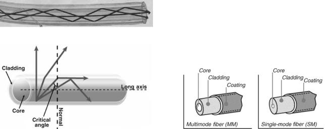
For almost 400 years, it has been well known from classical optics that when light enters a medium with a lower refractive index it bends away from the imaginary line perpendicular to the surface of the medium. However, if the angle of incidence is sufficiently large, the angle in the medium with lower refractive index can reach 908. Since the maximum possible angle of refraction is 908, the light with higher angles of incidence would not enter the second medium and will be reflected entirely back in the medium from which it was coming. This particular angle is called the critical angle and the effect is called total internal reflection.
The effect of total internal reflection that makes an optical fiber possible is depicted in Fig. 1. The light in an optical fiber propagates through the medium with high refractive index, which is called core (usually the silica glass). The core is surrounded by another medium with lower refractive index, which is called cladding (usually another type of the silica glass). If light reaches the core– cladding interface with an incident angle higher than the critical angle it will be entirely reflected back into the optical fiber. However, if light reaches the core–cladding in terface with an incident angle lower than the critical angle, it will leave the core and will be lost. Thus, optical fibers can propagate light only at a certain angular composition, which depends on the critical angle of the core– cladding interface and thus on the refractive indexes of the core and the cladding.
Light, being continuously reflected from the core– cladding interface, can propagate very far through an
optical fiber, even if the fiber is bent or is placed in a highly absorptive medium. However, if the fiber is bent too much some of the light can escape the core of the fiber. Other sources of losses are impurities in the glass. Typical optical fiber has 50–60% losses per kilometer of its length.
Throughput
There is a limit on how much light an optical fiber can transmit. Intuitively, it should be limited by an acceptance angle of a fiber and its area. This rule is often formulated as a conservation of throughput principle, which is a very general principle in optics.
For a given aperture in an optical system, the throughput T is defined by
T ¼ SðNAÞ2
where S is the area of the aperture, and NA is numerical aperture of the optical element equal to the sine of the maximum divergence angle of radiation passing through the aperture (1). Conservation of throughput says that it can be no greater than the lowest throughput of any aperture in the system (2). It is very important to take the throughput of the fiber into consideration when one calculates the power, which can pass through the fiber.
Propagation Modes
By solving Maxwell’s equations for an optical fiber one can find various patterns of the electromagnetic field inside the fiber. Those patterns are modes of the fiber. There are two main types of an optical fiber. The fiber can be either single mode or multimode (see Fig. 2). The difference between these types is the number of modes that the fiber can propagate.
A single-mode fiber is a fiber through which only one mode can propagate. Usually, a single-mode fiber has a very small core, 5–10 mm in diameter. Due to their size and also because of their small NA, these fibers have a very small throughput. In medicine, such fibers are used, for example, in confocal microscopy because of the requirement for the small core diameter of the fiber tip (see the section Fiber-Based Confocal Microscopy) and OCT. However, in OCT they are used not for their size, but because the coherence of the light pulse is critical for OCT to work (this is described in detail in the section Optical Coherence Tomography characterization of flexible imaging fiber Bundles).
Figure 1. Total internal reflection confines light within optical |
Figure 2. Types of fibers. (From Basic Principles of Fiber Optics, |
fibers. (From The Basics Of Fiber Optic Cable, ARC Electronics.) |
Corning Incorporated # 2005.) |

Figure 3. Fiber components. (From Basic Principles of Fiber Optics, Corning Incorporated # 2005.)
The core of the multimode fiber can be much larger, somewhere between 50 and 1500 mm in diameter. These fibers are ideal for light delivery and collection, and are used in medicine when the throughput is important (see the Section Spectroscopy).
In addition to the single-mode and multimode fibers, there is another important type, that is, a polarizationmaintaining fiber. The polarization-maintaining capability of a fiber is provided by the induced birefringence in the core of the fiber. This birefringence causes the polarization in these fibers to remain in the axis that it was launched into the fiber and is not changing randomly as in the regular fiber.
There are two main types of the polarization-maintaining fibers: one with the geometrical birefringence and another with the stress-induced birefringence. Geometrical birefringence is created by the elliptically shaped core. The stress-induced birefringence is created by using two stress rods as a core.
In the application where fibers are exposed to the physical stress and temperature changes, the former type is used mostly since it maintains its polarization.
Optical Fiber Construction
Optical fiber consists of three main components: core, cladding, and coating as shown in Fig. 3. The fiber is constructed by drawing a solid glass rod in a high purity graphite furnace. The rod consists of a core with high refractive index inside a low refractive index cladding. Thus both core and cladding are produced from a single piece of glass.
After core and cladding are formed, the protective coating is applied to the fiber. This protective coating is called a jacket and it guarantees that the fiber is protected from the outside environment.
Types of Fibers
Transmission ranges of materials used for fibers are shown in Fig. 4 (3). Most lasers operate in the range from 300 to 2500 nm, where silica fibers have the best overall properties and thus are commonly used.
Ultraviolet, Visible, and Near-Infrared Fibers. Ultraviolet(UV), visible, and near-infrared (NIR) light spans the range from 200 nm to 2.5 mm. Visible and near-IR light
FIBER OPTICS IN MEDICINE |
303 |
Heavy metal halide
Chalcogenide glass
Hollow core
Fluoride glass
Sapphire
Silica
0 |
2000 |
4000 |
6000 |
8000 |
10000 |
12000 |
Wavelength [nm]
Figure 4. Transmission ranges of materials used for fibers (From Ref. 3)
propagates in the silica-based fibers with practically no losses due to the low absorption of the order of tenths of percent per meter. In the IR range (wavelength >2.4 mm) and UV (wavelength <400 nm) absorption is higher. The silica-based fiber absorption is caused primarily by hydroxyl radicals (OH), and thus is determined by OH concentration resulting from the presence of free water during the fiber production. Low OH concentration determines excellent transmission of these fibers in the NIR range up to 2.4 mm. At wavelengths longer than 2.5 mm, the absorption of silica limits the use of silica fibers. In the UV range, most of the silica fibers are usable down to 300 nm, particular the fibers with a high OH concentration. For shorter wavelengths fibers with both core and cladding made of silica, silica–silica fibers are used.
For applications in wavelengths <230 nm, special attention should be paid to the solarization effect caused by the exposure to the deep UV light. The solarization effect is induced by the formation of ‘‘color centers’’ with an absorbance at the wavelength of 214 nm. These color centers are formed when impurities (like Cl) exist in the core and cladding fiber materials, and form unbound electron pairs in the Si atom, which are affected by the deep UV radiation. Recently, solarization resistant fibers have been developed. It consist of a silica core, surrounded by silica cladding that is coated in aluminum, which prevents the optical fiber from solarizing. The fiber preform (a high grade silica rod used to make the fiber) is hydrogen loaded in a hydrogenrich environment that helps to heal the silicone–oxygen bonds broken down by UV radiation.
As far as power-handling capability is concerned, the typical glass optical fiber is quite adequate in applications where the laser beam energy is delivered continuously or in relatively long pulses such that the peak power in the optical fiber does not exceed power densities of several megawatts per square millimeter. When the laser energy is delivered in very short pulses, however, even a moderate energy per pulse may result in unacceptable levels of-peak power. Such may be the case of Nd-YAG lasers, operating in mode-locked or Q-switched configurations, which produce laser beam energy in the form of pulses of nanosecond duration or less. On the other hand, excimer lasers, which are attractive in a number of applications (4), generate energy in the UV range of the spectrum (200–400 nm) in
304 FIBER OPTICS IN MEDICINE
very short pulses; they, therefore, require solarizationresistant silica–silica fibers, which can transmit light en ergy at such short wavelengths and, at the same time, carry the high power densities.
The limitation on power-handling capability of a glass optical fiber is due to several nonlinear effects, for example, Raman and Brillouin scattering (5), avalanche breakdown (6), and self-focusing (7). Stimulated Raman scattering, which occurs when, because of molecular vibrations, a photon of one wavelength, say that of the laser, is absorbed and a photon of another wavelength, known as a Stoke’s photon, is emitted, has been observed at power densities of 6 MW mm 2. The time varying electric field of the laser beam generates, by electrostriction, an acoustic wave, which in turn modulates the refractive index of the medium and gives rise to Brillouin scattering. Thus, Brillouin scattering is analogous to stimulated Raman scattering wherein the acoustic waves play the same role as the molecular vibrations. Although the Brillouin gain is higher than the one measured for the stimulated Raman scattering, the latter is usually the dominant process in multimode fibers (8).
Under the influence of an intense electromagnetic field, free electrons, which may exist in the optical fiber as a result of ionized impurities, metallic inclusions, background radiation, or multiphoton ionization, are acceler ated to energies high enough to cause impact ionization within the medium. If the rate of electron production due to ionization exceeds the electron loss by diffusion out of the region, by trapping, or by recombination, then an avalanche breakdown may occur, resulting in material damage. If high enough power densities (>100 MW mm 2) are applied to the fiber core, avalanche breakdown is the main mechanism of permanent damage to the optical fiber. The fiber surface should be polished and chemically processed with great care to avoid reduction in the damage threshold level of the fiber surfaces. The latter is usually lower by two orders of magnitude than that of the bulk material as a result of the presence of foreign materials embedded during improper polishing or because of mechanical defects. The threshold of induced Raman and Brillouin scattering and avalanche breakdown can be further substantially reduced by self-focusing of the laser beam. Self-focusing may occur when the refractive index of the nonlinear medium increases with beam intensity. The possible physical mechanisms involved are vibration, reorientation, and redistribution of molecules, electrostrictive deformation of electronic clouds, heating, and so on. Thus, a laser beam with a transverse Gaussian profile causes an increase in the refraction index in the central portion of its path of propagation, and becomes focused toward the center. Self-focusing is counteracted by the diffraction of the beam and the balancing effects of the two determine the threshold of power that causes selffocusing; for glass it was found to be 4 MW. Damage to optical fibers can also occur if a pulsed-laser beam is not properly aligned with the entrance face of the fiber (8,9).
IR Fibers. For the IR region beyond 2500 nm, materials other than silica are being used. These IR fibers can be classified into three categories: IR glasses fibers, crystal-
line fibers, and hollow fibers (10,11). Fluorozirconate and fluoroaluminate glass fibers can be used in the 0.5–4.5 mm region. Commercially, they are produced in diameters from 100 to 400 mm. Because of their low melting point, they cannot be used >150 8C; however, they have a high damage threshold. The refractive index is similar to silica ( 1.5) and the transmission is >95% for several meters. For longer wavelengths (4–11 mm) chalcogenide glass fibers are available in diameters of 150–500 mm. The disadvantage of these fibers is that they are mechanically inferior to silica fibers and are toxic. They have high Fresnel reflection because of the high refractive index (2.8) and relatively high absorption; as a result they have low transmission [losses are several tens of percent per meter (12)].
The crystalline fibers can be better candidates for the mid-IR range. Sapphire can be grown to a single crystal with a diameter of 200–400 mm, which is strong, hard, and flexible (13). It can be used up to a wave length of 4 mm. Sapphire, however, has a high index of refraction (1.75), which produces rather high reflection losses at each surface. Silver halide and thallium halide polycrystalline alloys (e.g., KRS-13), in contrast, can successfully transmit even high power CO2 light (14). From these alloys, good quality fibers are manufactured with high transmission of a few dB m 1 and that are insoluble in water, are nontoxic, and are fairly flexible.
Hollow fibers are built as flexible tubes, which are hollow inside, that is with air. They transmit light in the whole IR range with high efficiency (15–17). One type of these fibers comprises metallic, plastic, or glass tubing that is coated on the inside with a metallic or dielectric film with a refractive index n>1 (18). Another type has the tubing coated with a dielectric coating of n<1 for 10.6 mm on the inside of hollow glass (15) or crystalline tubes (19). The losses are 0.4–7 dB m 1 depending on the core size. The losses due to bending are inversely proportional to the core radius. Power transmissions >100 W have been achieved. The damage threshold for high power densities is comparable with that of solid core fibers. It has been reported that the dielectric-coated metallic hollow fiber is the most promising candidate for IR laser light transmission. The standard hollow fiber is 2 m in length with an inner diameter of 0.7 mm and has transmission >75% of Er-YAG or CO2 laser light under practical usage conditions (20).
ILLUMINATION APPLICATIONS
Introduction and Applications
Optical fibers are used for various illumination needs. The use of fiber optics bundles allows illuminating the desired area without the problem associated with the presence of the lamp-based light source.
For example, the fiber bundle brings the visible light to illuminate the area under examination with the colposcope and surgical microscope while the light source is placed in the area not interfering with the physician’s activities.
In endoscopy, the fiber optic bundles are incorporated into the small diameter flexible cylindrical body of the endoscope, which is dictated by the necessity to pass through narrow (<2 cm at the most) pathway of lumens
Figure 5. Headlight attached to the head bend on the surgeon head. The light from the lamp is transmitted through the fiber bundle to the output lens. (From www.luxtec.com.)
of the human body. The fiber optic bundles are used to bring the light down to the distal end and illuminate the target tissue, which the physician is examining through the imaging channel of the endoscopes.
In surgery, especially in microsurgery, dentistry, and so on fiber optic bundles are used to build a headlight, which creates bright illumination of the surgery area where the
FIBER OPTICS IN MEDICINE |
305 |
surgeon eyes are pointed. Here, the fiberoptic illumination allows mounting the output lens on the headband of the surgeon and leaving their hands free for the operation (see Fig. 5). Recent development in the fiber optics flat and flexible illumination panels (see below) allows bringing the visible light inside the deep cavities of the human body for illumination during surgery.
In ophthalmology, early application of fiber optic illumination has included its use as a light source in the indirect ophthalmoscope. The resulting small light spot at the distal end of the optical fibers allows for the use of variable apertures and provides sharply focused and uniformly illuminated circles of light upon the retina (21). Fiber optic illuminators are also used in conjunction with intraocular surgery. Thus a variety of miniature devices are available for the visualization of the interior of the eye to provide improved illumination in microsurgery of the retina and vitreous.
Currently, a number of companies are developing the ‘‘solid-state’’ light based on the light emitting diodes (LED). The advantages of this type of illumination is that it produces much less heat and emits in the visible spectral range thus making the illumination fiber bundle less useful for some a pplications. However, it will take another decade before this type of the light will become commercially viable.
In addition to transmitting the light through the fiber bundle to the target for illumination, the fiber optics often serves to shape the light in the form most advantages for the application. For example, in the form of the rigid or flexible flat panel that can be used during almost any deep cavity surgery. These fiberoptic panels are made of woven plastic optical fibers as shown in Fig. 6.
Figure 6. Principle of the fiber optics panels with the side emission. (From www.lumitex.com.) (a) All fiber optics illumination bundles, li ght enters the panel through each highly polished fiber end. Here, the computer controlled ‘‘macrobends’’ in the fibers cause the transmitted light to be emitted from the sides of the fibers through the cladding. Precisely engineered construction causes all light to be emitted uniformly along the length of the panel. (b) Layers of fiber optic weave are assembled together with double-sided adhesive into as many as eight layers. A mylar reflector is laminated to the back and a clear vinyl top layer is added for extra durability. For some applications (e.g., LCD backlighting), a semitransparent diffuser layer is placed between the top weave layer and the clear vinyl. The optical fibers extend from the panel in cable form and are bundled into a brass ferrule and highly polished. These ferrules are then connected to a remote light source.
306 FIBER OPTICS IN MEDICINE
Requirements for Illumination Fibers
A thin optical fiber is obtained by drawing in a furnace a glass rod inside glass tubing, which together form the high refractive index core and the low refractive index cladding, respectively. The core material usually used for the illumination fibers is silica, which, as was discussed earlier, is the best material for the visible spectral range. When drawn to a core diameter of 25 mm or less, the optical fiber is quite flexible, allowing for bending radii of <1 cm.
Light Sources Used with Illumination Fibers. The light sources for the fiberoptic illuminators are tungsten or quartz halogen projection lamps, mercury or xenon high pressure arc in quartz glass enclosures, and metal halide lamps. Color temperatures of tungsten sources vary between 2800 and 3500 K, which is a low color temperature with the illumination appearing yellow. Arc and halide lamps are used in the commercially available illuminators and provide light at the color temperature of 5400 K.
These light sources are a black body type radiator, thus they radiate into the sphere, that is, solid angle of 4p steradian and the amount of the output light they emit is almost proportional to the emitting body (filament, for the tungsten lamps, and arc, for other types). Thus they have the emitting body of >1 mm2 for the arc lamp and much greater for the tungsten and quartz halogen lamps.
Coupling Efficiency. The fact that the light source radiates in 4p steradian from the emitting body lead to requirements that the optical fibers used for the illumination have a high aperture and sufficient cross-section. To transmit the required illumination through the bundle and keep the fibers flexible, the conventional practice is to gather a lot of thin flexible fibers into a bundle, with the ends bound and polished. This bundle is almost as flexible as the single fiber. The fibers in the ends of the illumination fiber bundles are arranged at random and these bundles are called incoherent . This organization of the fibers in a bundle, in addition to being inexpensive to assemble, is also sometimes useful to provide uniform illumination at the output end.
Various schemes have been employed to maximize the light intensity delivered from the source to the fiber or fiber bundle and to obtain uniform illumination at the distal end of the fiber. For example, a special reflecting mirror, in the form of an ellipsoid of revolution, has the light source and the fiber input at the focal points with the major axis of the ellipsoid at an angle to the receiving fiber. However, note that light lamp sources, as opposed to lasers, could not be focused or concentrated onto areas smaller than their emitting body without considerable loss of the luminous flux. This follows from the fundamental relationship in radiometry, which states that the radiance of an image cannot exceed that of an object for the case when both lie in a medium with the same index of refraction (22). Consequently, the optimum illumination from an optical fiber is obtained when the image of the source completely fills the entry face of the fiber and the cone of light forming this image is equal to the numerical aperture of the fiber. In some cases, when the light source consists of a
filament, the use of reflectors increases the effective area of the source by redirecting light rays through the voids in the filament.
Removal of Heat, UV, and IR Radiation. All lamps produce heat directly or by absorption of light in the visible to IR spectral ranges. Also, the UV radiation portion of the spectrum may be hazardous to the eyes and illuminated tissue. The high intensity light sources needed to deliver adequate illumination to and through the optical fiber cause the latter to become very hot. In the case of fiber bundles, the heat generated at the proximal end of the fibers requires that they not be bonded with epoxy, but instead be fused together. In some cases this may also apply to the distal end if enough heat is conducted through the fiber or is generated by absorption of light in the fiber. Of course, this is highly undesirable and should be avoided. After all, one of the main objectives of the use of illumination fibers is to keep the heat of the light source away from the area being illuminated. Indeed, the early applications of optical fibers were referred to as ‘‘cold-light’’ illumination. Special provisions must, therefore, be made to dissipate and divert large amounts of heat. Most light sources utilize dichroic reflectors and/or heat filters to block the heat from reaching the fiber.
Transmission. The light propagating through the optical fiber is attenuated by bulk absorption and scattering losses. These losses vary with the wavelength of light and are usually higher at short wavelengths, that is, the blue end of the visible spectrum of 400–700 nm. In most illumination applications, the typical length of the fibers does not exceed 2 m and thus the attenuation of light due to absorption is of no consequence. Antireflection coating can reduce Fresnel losses due to reflection at the end faces of the fiber.
The faithful rendition of color in viewing depends on the spectral content of the light illumination. This is of particular significance in medicine where the diagnosis of disease is often determined by the appearance and color of organs and tissue. Hence, optical fibers made of plastic materials, for example, polystyrene for the core and Lucite, polymethylene methacrylate (PMMA), for the cladding, despite their flexibility and low cost, do not find extensive use as illumination fibers.
DIAGNOSTIC APPLICATIONS
Introduction
One of the earliest applications of optical fiber in medicine were in imaging. The bundle of the optical fibers has been used to transmit image from the distal to the proximal end, where the physician could see the image of the target tissue in real time. The device using this technique is known as an endoscope. The endoscopes are used widely in current medical practice for imaging of lumens in the human body.
In the past 20 years, many new diagnostic applications of fiber optics have appeared as a result of the developments in biomedical optics (23). Most all of them utilize a single or a few fibers. Some of them, for example OCT (24)
and confocal imaging (CI) (25) use scanning to produce the images of the lateral or axial cross-sections of the body. Others are utilizing the spectroscopic differentiation of the tissue, using natural (23) or man-made markers (26). Among these techniques, fluorescence (23), reflectance (23), light scattering, and Raman spectroscopic methods (27) are most promising and thus most developed.
Another new area for the application of fiber optics in medicine is the fiberoptic biosensor (FOBS). This is a sensor consisting of optical fiber with a light source and detector and an integrated biological component that provides the selective reaction to the biochemical conditions of the tissue and body fluids. These sensors have been applied for glucose and blood gas measurements, catheterbased oximetry, billirubin, and so on. The detailed discussion about the principle and applications of these sensors is in ‘‘Optical Sensors’’ article of this encyclopedia.
Imaging
Endoscopy. The word endoscopy derives from two Greek words meaning ‘‘inside’’ and ‘‘viewing’’. Its use is limited to applications in medicine and is concerned with visualization of organs and tissue by passing the instrument through natural openings and cavities in the human body or through the skin, that is percutaneously. The endoscope has become an important and versatile tool in medicine. It provides a greater flexibility than it is possible with instruments that consist of a train of optical lenses, and transmits illumination to the distal end of the probe. The greater flexibility of the flexible endoscope enables the visualization around corners and the eliminati on of ‘‘blind areas’’ obtained with the rigid instrument. It should be noted that optical fibers are used to deliver illumination light in rigid endoscopes that in some cases may employ lenses for image transmission.
Endoscopes, which utilize optical fibers to transmit the image from the distal to the proximal end, are often called fiberscopes to differentiate them from the video or electronic endoscopes where a semiconductor imager is placed at the distal end and the image is transmitted electronically. Progress in the production of the relatively inexpensive high quality miniature semiconductor imagers based on Charge Coupled Device (CCD) technology and Complementary Metal Oxide Semiconductor (CMOS) led to the development of the high quality electronic (video) endoscopes. Currently, most of the endoscope vendors produce such endoscopes. It appears that these video endoscopes produce higher quality images with considerably higher magnification (28) and are replacing the fiberscopes where it is prac tical (29–31). However, a large number of fiberscopes are still used in the clinics and new fiberscopes are being sold (e.g., see www.olympusamerica.com). Moreover, in the areas that require thin and ultrathin endoscopes of <2–4 mm (32), fiberscopes are still the only practical solutions. The general discussion on endoscopy, its features, and applications is presented in the Endoscopy article. This article will primarily discuss fiberscopes.
In addition to the imaging and illumination channels, a typical endoscope includes channels to accommodate tools for biopsy to aspirate liquids from the region being
FIBER OPTICS IN MEDICINE |
307 |
inspected, and to inflate the cavity or to inject clear fluids to allow for better visualization. The overall dimensions of such instruments vary between 5 and 16 mm in diameter, the thinner versions being smaller and more versatile than the corresponding rigid systems. The fiberscope can be made as long as nece ssary, since the light losses in most fibers made of glass cores and cladding are tolerable over distances of up to several meters. These images can be recorded using film, analog and digital still, and video cameras.
Most of the fiberscopes use similar optical structures and vary mainly in length, total diameter, maneuverability, and accessories, for example, biopsy forceps. The diameter of the individual glass fibers in the image-conveying aligned bundle are made as small as possible limited only by the wavelength of the light to be transmitted. In practical applications, the diameter is ranging from 2 to 15 mm. Moreover, if the fibers are densely packed, cross-talk problems may arise due to the evanescent electromagnetic field (light waves) in each individual fiber (33).
A variety of fiberscopes have been developed, each with features that are best suited for specific applications.
Transmission of Images Through Optical Fibers. As shown in the section General Principles of Fiber Optics, an optical fiber cannot usually transmit images. However, a flexible bundle of thin optical fibers (obviously, with silica core) can be constructed in a manner that does allow for the transmission of images. If the individual fibers in the bundle are aligned with respect to each other, each optical fiber can transmit the intensity and color of one object point. This type of fiber bundles is usually called a ‘‘coherent’’ or ‘‘aligned’’ bundle. The resulting array of aligned fibers then conveys a halftone image of the viewed object, which is in contact with the entrance face of the fiber array. To obtain the image of objects that are at a distance from and larger than the imaging bundle, or imaging guide, it is necessary to use a distal lens or lens system that images the distal object onto the entrance face of the aligned fiberoptic bundle. The halftone screen-like image formed on the proximal or exit face of a bundle of aligned fibers can be viewed through magnifying systems or on the video monitor if this exit face is projected onto the video camera.
Fabrication of Flexible Imaging Bundles. The fabrication of flexible imaging bundles involves winding of the optical fibers on a highly polished and uniform cylinder or drum, with the circumference of the latter determining the length of the imaging structure. The aligned fibers can be wound directly from the fiber-drawing furnace or a separate spool of individual fibers. When the entire bundle is obtained in a single winding process, similar to a coil, an overhang of fibers wound on the outer layers develops after the structure is removed from the winding cylinder. Such overhang can be eliminated by winding single or a small number of layers and cutting them into strips to form the aligned fiber bundle. This process, although more laborious, usually renders better uniformity in the imaging bundles. Some users find the evenness of the fiber arrangement distracting and prefer the irregular structure. This may be compared
308 FIBER OPTICS IN MEDICINE
with the viewing of a television image wherein the horizontal line scan has accentuated by imperfect interlacing. In either method, the diameter of the fibers is on the order of 10 mm, which is thinner than hair or about the size of a strand in a cottonball, and must therefore be soaked in binding epoxy during the winding process. When the completed imaging bundle is cut and remove d from the drum, its ends are bound to secure the alignment and the epoxy is removed along the structure to let the individual fibers remain loose, and thus flexible. A flexible imaging bundle can also be obtained by first drawing a rigid preform made up of individual optical fibers, each with a double coating, where the outer cladding is chosen to be selectively etched afterwards. Such a structure has nearly perfect alignment, sin ce the preform can be constructed of fibers thick enough to allow parallel arrangement and the individual fibers in the drawn bundle are fused together without any voids be tween them. Moreover, such fabrication technique, as compared with the winding method, is far less expensive since it permits batch processing.
The size of the imaging bundle varies from 1 to 2 mm in diameter for miniature endoscopes, for example, angioscopes or pediatric bronchoscopes, where the fiberscopes are currently primarily utilized, to 6 mm in diameter for large colonoscopes, and lengths exceeding 2 m. Large imaging bundles may consist of as many as 100,000 individual fibers (28), each fiber providing one point of resolution or pixel. For such large numbers of fibers, it is often necessary to fabricate the final device by draw ing first fiber bundles containing a smaller number of fibers and then joining them together to form a larger structure.
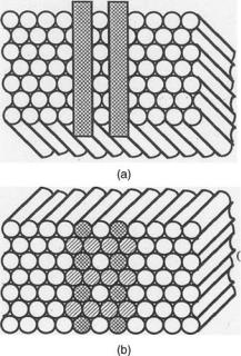
Characterization of Flexible Imaging Fiber Bundles. The resolution attainable with a perfectly aligned fiberoptic imaging structure is determined by the fiber diameter. For a hexagonal configuration, the resolution in optical line pairs per millimeter is, at best, equal to, and usually slightly <1/2d, where d is the fiber diameter in millimeters. Figure 7 shows a cross-section of an imaging bundle of fibers aligned in a closely packed hexagonal pattern, i.e., each fiber has six closest neighbors. In Fig. 7a are shown two opaque stripes separated by a distance equal to their width, which are placed at the distal end of an entrance face of the imaging bundle. When this end is illuminated, the corresponding fibers at the output or proximal exit end of the bundle will be either partially or totally darkened, depending on the relative location of the opaque stripes with respect to the fiber pattern. In Fig. 7b, the partially illuminated fibers indicate that the smallest resolvable separation of the two stripes is equal to twice the fiber diameter. In practice, the packing of the fiber bundle is often not perfect, leaving spaces between the fibers; thus, the line resolution is further reduced and is usually <1/2d. For a typical imaging bundle in endoscopy, the diameter of the individual fiber is 10 mm and, therefore, the resolution is better than 50 line-pairs mm 1. This resolution is considerably poorer than in most lens systems.
The line resolution for the hexagonally aligned imaging bundle does depend on the orientation of the stripes (Fig. 7). Thus, for an orientation different from that shown in Fig. 7, the line resolution may be somewhat different from that
Figure 7. Image transmission of two opaque stripes from (a) distal end to (b) proximal face of an imaging fiber optics bundle.
obtained. The spatial variance of the image transfer properties of imaging bundle has led to the use of averaging techniques in the evaluation of their limits of image resolution (34). The modulation-transfer function (MTF) of an imaging bundle is the contrast response at its exit face to a sinusoidal test pattern of varying spatial periodicity imaged onto the input or entrance face. The fabrication of an imaging bundle may result in the misalignment or deviation from perfect alignment of the adjacent fibers. A method of evaluation of the image-conveying properties of practical imaging bundles has been developed (35), which takes into account the fact that the arrangement of the fibers may differ at the input and output faces of the imaging bundle. It also uses a statistical approach in determining an average modulation-transfer function. The aligned fiber bundle exhibits a mosaic pattern that represents the boundaries of the individual fibers and that appears superimposed on the viewed image. Hence, the viewer sees the image as if through a screen or mesh. Any broken fiber in the imaging bundle appears as a dark spot. In some applications, these two features can be very annoying and distracting, although most medical practitioners have become accustomed to these peculiarities and have learned to discount them. In some sense, it is comparable to viewing through a window with a wire screen, which in most cases is unnoticed.
Rigid Imaging Bundles. Fiberoptics bundles composed of individual optical fibers far smaller than those described earlier can be obtained by drawing the entire assembly in the furnace in a manner that preserves their alignment. This method is similar to that employed in the preparation of flexible imaging structures by etching a double-clad rigid imaging bundle. However, since the fibers become fused together during the drawing process, the structure
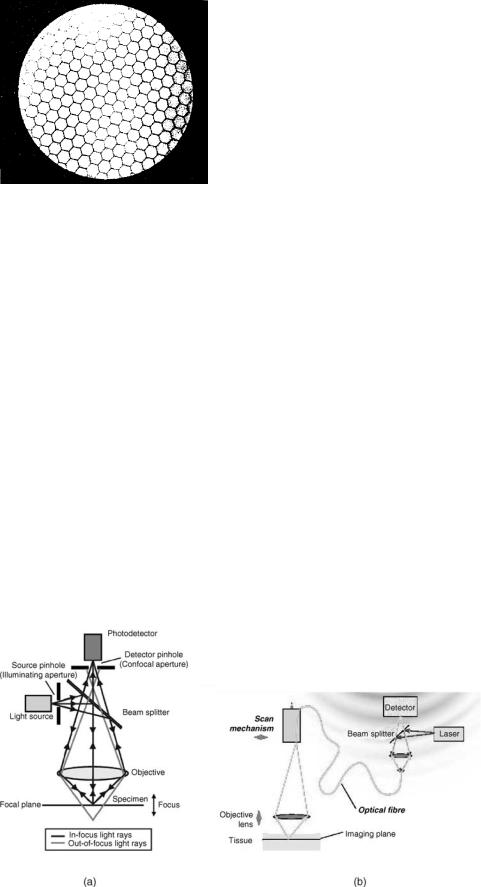
Figure 8. Cross-section of the imaging bundle.
remains a rigid solid-glass rod. A segment of a cross-section of such an imaging bundle, which is 0.5 mm in diameter and contains 11,000 fibers, each 4.2 mm in diameter, is shown in Fig. 8. The honeycomb pattern represents the boundaries of the individual fibers and is superimposed on the image, similar to the flexible fiberoptic imaging bundle.
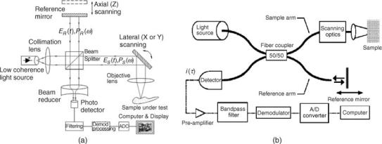
Fiber-Based Confocal Microscopy. Confocal imaging (CI) is based on illuminating a single point on the sample and collecting scattered light from the same single point of the sample (Fig. 9a). The illumination point on the sample is the image of the illumination pinhole and is imaged into the detector pinhole, thus making both pinholes and the illuminated spot on the sample optically conjugated. In this way, stray light from points outside the collection volume is effectively filtered, improving contrast, particularly for scattering media, for examples, biological tissues. Scanning the position of this point on the sample and acquiring the signal from each position creates a lateral image of the sample. For axial cross-sectional imaging, the focal point on the sample is axially moved while acquiring the signal from each position. Combining both lateral and axial scans provides a perpendicular cross-sectional image of the tissue. The nature of the signal from the illuminated
FIBER OPTICS IN MEDICINE |
309 |
point depends on the specific embodiment. Either backscattered or fluorescent signals are most often used for CI; however, other signals have been collected and proven clinically useful.
Both pinholes contribute to depth sectioning ability. The source pinhole causes the illuminating irradiance to be strongly peaked at the image formed by the objective and to fall off rapidly both transversely and along the line of sight (depth). There is, therefore, very little light available to illuminate out-of-focus volumes. This implies that these volumes will not significantly mask the image of the more brightly illuminated focal region. The detector pinhole acts similarly. It is most efficient in gathering the radiation from the volume at the focal point, and its efficiency falls off rapidly with distance, both transversely and in depth. Together they assure that the totality of the out-of-focus signal is strongly rejected.
Confocal imaging provides enhanced lateral and axial resolutions and improved rejection of light from the out-of– focus tissue. As a result, the confocal imaging (CI) can achieve a resolution sufficient for imaging cells to depths of several hundreds of microns. At these depths, CI has been especially helpful in imaging the epithelium of many organs, including internal organs via endoscopic access. Images displayed by the CI system are similar to images of histopathology slides under high resolution conventional microscope, thus, are familiar to the physicians.
The fiberoptical confocal microscope has been introduced in late 1980s and early 1990s (see, e.g., Ref. 37). In this kind of the CI microscope, the light source is not a point source, but the tip of an optical fiber, and the signal is collected by another optical fiber that delivers the signal to a detector. This makes the CI system compact and thus convenient in numerous biomedical applications.
There are a variety of optical systems and scanning arrangements, which allows for optimization of the CI device for the required image and particular clinical application (25). For example, the scanning can be or ganized by moving the fiber tips, especially, when the common fiber is used for the illumination and detection as shown in Fig. 10b, or by moving the objective lens or by placing in
Figure 9. Confocal microscopy. (a) Principle of confocal arrangement. (From MPE Tutorial, Coherent Incorporated # 2000.) (b) Possible implementation of fiber-based confocal microscope (36).
310 FIBER OPTICS IN MEDICINE
Figure 10. Optical coherence tomography (OCT). (a) Principle of OCT (From Wikipedia.org).
(b) Possible implementation of fiber-based OCT (38).
the pinhole plane an output face of coherent fiber bundle and scanning an mage of a pinhole at the entrance end of it.
The CI system can provide a cellular level resolution: A lateral integrated image of tissue (similar to C-scan imaging), a lateral cross-sectional image at the desirable depth of tissue, a perpendicular-to-the-surface cross-sectional image of the tissue (similar to B-scan imaging), and a combination of the above images, thus a three-dimensional (3D) image of tissue. In each case, the CI system could be optimized to achieve the best overall performance while utilizing the same basic platform. The application of the CI imaging has been successfully demonstrated in diagnostics of intraepithelial neoplasia and cancer of the colon (39). It is reasonable to envision that the CI-based endoscope will be used for the screening of Barrett’s esophagus and cancer and other areas of the upper GI tract. It appears that there is potential for application of the CI device combined with one of the scattering-based spectroscopies for the vulnerable plaque screening and triage.
The optical fibers used for the CI application are usually a single mode type because of the requirement for the small core diameter of the fiber tip as discussed above.
Optical Coherence Tomography. Optical coherence tomography is a relatively new technology and has been developed and investigated for the past 15 years (38). It uses the wave property of light called coherence to perform ranging and cross-sectional imaging. In OCT systems, a light beam from a light source is split into a reference light beam and a sample light beam (see Fig. 10a). The sample light beam is direct ed onto a point on the sample and the light scattered from the sample is combined w ith the reference light beam. The combined reference and sample light beams interfere if the difference of their optical paths is less than the coherence length. The reference and the collected sample beam are mixed in a photodetector, which detects the interference signal. The light source used in OCT has a low coherence length so that only the light s cattered from the sample within the close proximity around a certain depth will satisfy this condition. The strength of the interference signal corresponds to the scattering around this depth. To acquire the signal from another depth in the sample the optical pa th of one of the beams
is changed so that the same condition is now satisfied by the li ght scattered from another depth of the sample. The component of the OCT system providing this change is called an optical delay line. By sequentially changing the optical path of one of the beams and processing the photodetector output, a cross sectional image of the sample is generated. By laterally moving the sample beam along the sample provides a perpendicular cross-sectional image of the sample. The OCT image is similar to high frequency ultrasound B-scan images.
Usually a moving mirror in the optical path of one of the beams performs the continuous scan of the optical path. The shortest coherence length of available light sources allows the OCT systems to achieve a depth resolution higher than in high frequency ultrasound imagers, but lower than in confocal imaging. As a direct correlate, the depth penetration of OCT systems is lower than for the high frequency ultrasound imagers and higher than the confocal imaging. These parameters make OCT a useful technology in the biological and medical examinations and procedures that require good resolutions to 2 mm depths.
The OTC systems utilizing the fiberoptic components are most often used (Fig. 10b). These systems are compact, portable, and modular in design. The sample arm of the OCT can contain a variety of beam-delivery options including fiberoptic radialand linear-scanning cathe- ter-probes for clinical endoscopic imaging. The aiming beam is used so that the clinicians could see the location on the tissue where the OCT catheter is acquiring image. The optical fiber based OCT systems require using single mode fibers in both reference and sample arms to keep the coherence of the light guided by the fiber. In some cases, when the OCT system is using the polarization properties of the light, it must utilize the polarization-maintaining fibers.
There is a variety of OCT optical systems and scanning arrangements, which provide room for optimization of the OCT device for the specific clinical application. Recently, several system modifications of the basic OCT have been reported; for example, Fourier transform OCT (40,41), spectroscopic OCT (42), and polarization OCT (43). Some of them appear to promise practical OCT systems with higher data acquisition rates, higher resolution (comparable with
the resolution of CI), better noise immunity, or capabilities to acquire additional information on tissue.
In the endoscopic applications, the sample arm fiber is designed as a probe that goes through the endoscope to the target tissue. There are a number of OCT probes developed and suggested designs (44–54) that provide room for optimization of the OCT device for the specific clinical application. A number of successful clinical studies have been carried out demonstrating the clinical applicability of the endoscopic fiber OCT technique for clinical imaging, for example, for imaging of Barrett’s esophagus (54) and esophageal cancer (55), bile duct (56), and colon cancer (55).
Spectroscopy
Reflectance and Fluorescence Spectroscopy. Diffuse reflectance spectroscopy is one of the simplest spectroscopic techniques for studying biological tissue. Light delivered to the tissue surface undergoes multiple elastic scattering and absorption, and part of it returns as diffuse reflectance carrying quantitative information about tissue structure and composition.
This technique can serve as a valuable supplement to standard histological techniques. Histology entails the removal, fixation, sectioning, staining, and visual examination of a tissue sample under the microscope. Tissue removal is subject to sampling errors, particularly when the lesions are not visible to the eye. Also, the multiple-stage sample preparation process is time-consuming, labor intensive, and can introduce artifacts that are due to cutting, freezing, and staining of the tissue. Most importantly, the result is largely qualitative in nature, even though quantitative information is available through techniques, for example, morphometry and DNA multiploidy analysis.
Spectroscopy, in contrast, can provide information in real time, is not greatly affected by artifacts or sampling errors, and can provide quantitative information that is largely free of subjective interpretation. Because it does not require tissue removal, it can be conveniently used to examine extended tissue areas.
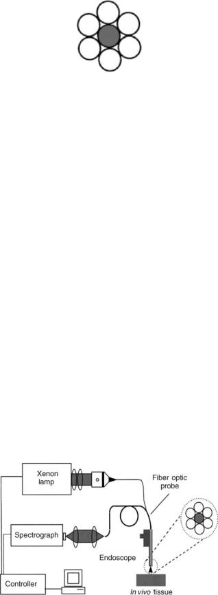
Usually, light is delivered and collected using an optical fiber probe that can be advanced through the accessory channel of the endoscope and brought into contact with the tissue. The probe can consist of several delivery and collection fibers. Probably the simplest geometry is a central optical fiber for light delivery and six fibers for light collection arranged in a circle around the central fiber. In Zonios et al. (57), all fibers had a 200 mm core diameter and a NA of 0.22, and were packed tightly with no gap between them. The probe tip was fitted with a quartz shield 1.5 mm in length and in diameter, which provided a fixed delivery and collection geometry with uniform circular delivery and collection spots in the form of overlapping cones. The tip was beveled at an angle of 178 to eliminate unwanted specular reflections from the shield–tissue interface (see Fig. 11).
To extract quantitative properties of tissue collected with the above probe the model of light transport in tissue should take into account probe geometry. To find the total light collected by the probe, diffuse reflectance from a point source must be integrated over the spatial extent of the light delivery and collection areas, characterized by
FIBER OPTICS IN MEDICINE |
311 |
Figure 11. Configuration of fibers in a typical reflectance and fluorescence optical probe. Probe contains six fibers for light collection arranged in a circle around the central fiber.
radii rd and rc, respectively. Assuming the incident light intensity to be uniform over the entire delivery area, the diffuse reflectance Rp(l) collected by the probe is given by (57).
1 |
rc |
2p |
rd |
|
||
ð0 |
rdr ð0 |
df ð0 |
Rðl; jr r0jÞr0dr0 |
|||
R pðlÞ ¼ |
|
|||||
rd2 |
||||||
where rd and rc are radii of the delivery and collection spots of the fiber optics diffuse reflectance probe and R(l,jr r0j) is diffuse reflectance predicted by the physical model, which depends on tissue morphological and biochemical composition.
A similar probe (Fig. 11) can be used for fluorescence spectroscopy measurements. For fluorescence measurements, it is especially important that delivery and collection signals are delivered over the separate optical fibers. This is because intense illumination light can easily induce certain amount of fluorescence in the delivery fiber. This fluorescence of the fiber is likely to be weak, however, tissue fluorescence is also very weak. Thus if the delivery and collecti on fibers coincide, the fluorescence from the probe itself would significantly perturb the tissue fluorescence observed by the instrument. Hence, fluorescence fiber probes should always have separate delivery and collection fibers.
Light Scattering Spectroscopy. In addition to the multiply scattered light described by the diffuse reflectance, there is a single scattering component of the returned light that contains information about the structure of the uppermost epithelial cells (58). It has been shown that light scattering spectroscopy (LSS) (Fig. 12) enables
Figure 12. Schematic diagram of the LSS system (59).

312 FIBER OPTICS IN MEDICINE
quantitative characterization of some of the most important changes in tissues associated with precancerous and early cancerous transformations, namely, enlargement and crowding of epithelial cell nuclei (58,60). Typical nondysplastic epithelial cell nuclei range in size from 4 to 10 mm. In contrast, dysplastic and malignant cell nuclei can be as large as 20 mm. Single scattering events from such particles, which are large compared to the wavelength of visible light (0.5–1 mm), can be described by the Mie theory. This theory predicts that the scattered light undergoes small but significant spectral variations. In particular, the spectrum of scattered light contains a component that oscillates as a function of wavelength. The frequency of these oscillations is proportional to the particle size. Typically, normal nuclei undergo one such os cillation cycle as the wavelength varies from blue to red, whereas dysplastic/malignant nuclei exhibit up to two such oscillatory cycles. Such spectral features were observed in the white light directly backscattered from the uppermost epithelial cell nuclei in human mucosae (60,61).
When the epithelial nuclei are distributed in size, the resulting signal is a superposition of these single frequency oscillations, with amplitudes proportional to the number of particles of each size. Thus, the nuclear size distribution can be obtained from the amplitude of the inverse Fourier transform of the oscillatory component of light scattered from the nuclei. Once the nuclear size distribution is known, quantitative measures of nuclear enlargement (shift of the distribution toward larger sizes) and crowding (increase in area under the distribution) can be obtained. This information quantifies the key features used by pathologists in the histological diagnosis of dysplasia and Carcinoma in situ (CIS), and can be important in assessing premalignant and noninvasive malignant changes in biological tissue in situ.
However, single scattering events cannot be directly observed in tissue in vivo. Only a small portion of the light incident on the tissue is directly backscattered. The rest enters the tissue and undergoes multiple scattering from a variety of tissue constituents, where it becomes randomized in direction, producing a large background of diffusely scattered light. Light returned after a single scattering event must be distinguished from this diffuse background. This requires special techniques because the diffusive background itself exhibits prominent spectral features dominated by the characteristic absorption bands of hemoglobin and scattering of collagen fibers (there is abundance of them in the connective tissue laying below the epithelium). The first technique of diffusive background removal uses a standard reflectance probe described in the section References and Fluorescence Spectroscopy. This technique is based on observation that the diffuse background is typically responsible for >95–98% of the total reflectance signal. Therefore, the diffusive background is responsible for the coarse features of the reflectance spectra. The diffusion approx- imation-based model may account for th is component by fitting to its coarse features. After the model fit is subtracted, the single backscattering component becomes apparent and can be further analyzed to obtain nuclear size distribution (58).
Figure 13. Design of the polarized fiber probe (62).
Another technique would use a special polarized probe. One possible implementation of the polarized probe is described by Utzinger and Richards-Kortum (62) (see Fig. 13). Recently, similar polarized fiber probe was developed by Optimum Technologies, Inc. The working principle of this probe is based on the fact that initially polarized light loses its polarization when traversing a turbid medium such as biological tissue. Consider a mucosal tissue illuminated by linearly polarized light. A small portion of the incident light will be backscattered by the epithelial cell nuclei. The rest of the signal diffuses into the underlying tissue and is depolarized by multiple scattering. In contrast, the polarization of the light scattered backward after a single scattering event is preserved. Thus, by subtracting the unpolarized component of the reflected light, the contribution due to the backscattering from epithelial cell nuclei can be readily distinguished. The residual spectrum can then be analyzed to extract the size distribution of the nuclei, their population density, and their refractive index.
Raman Spectroscopy. Raman spectroscopy is a very powerful technique, which should be capable of performing detailed analysis of tissue biochemical composition. However, in biological tissues the intensity of the Raman signal is only 10 9–10 11 of the intensity of the incident light. What make it even worse is the fact that fluorescence signal excited in tissue by the same incident light is much higher, 10 3–10 5 of the incident light. And if the signal is detected by the regular optical fiber probe it will also overlap with the fluorescence signal originated in the fiber
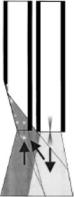
Figure 14. Design of the fiber tip of a typical fiber optic probe for Raman spectroscopy (62).
itself. Hence, development of a reliable biomedical Raman fiber probe is still a challenge.
In Fig. 14 one can see the design of a Raman fiber optic probe developed by Visionex Inc. It consists of a central delivery fiber and seven collection fibers. A bandpass filter is located in front of the delivery fiber and a longpass filter in front of the collection fibers. Those filters ensure that no laser light and fluorescence light originated in the delivery fiber can enter the collection fiber.
THERAPEUTIC APPLICATIONS
Introduction
In therapeutic application, fibers are used primarily as a part of light delivery system. Utilization of fibers allows for flexible and convenient methods of delivering light from bulky high energy light sources to the diseased location. Often, using the fiber optics delivery system makes otherwise inaccessible locations accessible. Variety of applications, light sources and energy requirements require different fibers with different features.
Fiber Surgical Applications
The monochromatic nature of laser beam en ergy, temporal coherence, and the ability to focus it onto a very small spot because of its spatial coherence, allow for efficient surgical methods, for example, tissue cutting or ablation, as well for the transmission of large amounts of power through a single optical fiber. This localized energy can be used to cauterize tissue by evaporation while reducing bleeding by coagulation. The use of lasers in surgical and other therapeutic applications is most effective when employed in conjunction with the flexible delivery systems and, in particular, with laser-beam delivery which is compatible with the endoscopy. Lasers utilized in medical applications range in wavelength from vacuum UV (excimer laser at 193 nm) to infrared (IR) (CO2 laser at 10.6/11.1 mm).
Laser-beam-delivery systems depend on the wavelength laser energy. At the present time there is no single delivery system that can be used over the entire range of medical lasers. The primary design considerations in such systems are efficiency, maximum power delivered, preservation of
FIBER OPTICS IN MEDICINE |
313 |
beam quality, and mechanical properties (flexibility, degrees of freedom, range, size, and weight).
Low efficiency (output power/input power) results in losses in the delivery system, which, in turn, requires higher power and thus more expensive lasers. Moreover, the power lost in the delivery system is generally dissipated as heat, resulting in a temperature rise that causes damage to the device, leading to a further deterioration of efficiency or catastrophic failure, Hence, efficiency, together with heat dissipation, can be considered to be the limiting factors in maximum power delivery.
A well-designed laser oscillator emits a highly collimated beam of radiation, which can then be focused to a spot size of just a few wavelengths, yielding power densities not achievable with conventional light sources. A useful delivery system should, therefore, preserve this quality of the beam as much as possible; otherwise the main advantages of using a laser are lost.
The most desirable flexible system should be easy to handle mechanically, perform a large variety of tasks, and, of course, still satisfy the above properties. From a mechanical point of view, the ideal laser-beam guide would be an optical fiber of small cross section and long enough to reach any site, at any orientation, over a wide range of curvatures, through openings and inside complex structures.
The choice of fibers for such system is mainly determined by the wavelength of the laser (see Fig. 4) and discussion in the section Types of Fibers.
Most lasers operate in the range of 300–2500 nm, where silica fibers have the best overall properties and, thus, are commonly used.
Outside this range, there are few wavelengths used for laser surgery, in IR, 2.94 mm of the erbium:YAG laser, 5–6 mm of the CO laser, 10.6/11.1 mm of the CO2 laser and in the UV, the 193 and 248 nm of the ArF and KF excimer lasers, respectively. In the infrared range, silver halide and sapphire are being used for the fiber core. Also, hollow fibers have become available for efficient guidance of infrared light with minimal losses (20,63). In the UV range, the solarization resistant silica/silica fibers are available (64) and hollow fibers have been reported recently (16,17). For pulsed lasers, utilization of fibers can be limited by the high peak powers, which could damage the fiber; for example, the peak power of 106 kW cm 2 is a threshold for silica. In this case, the flexible arms with reflective surfaces have to be used.
As far as power-handling capability is concerned, the typical glass optical fiber is quite adequate in applications where the laser beam energy is delivered continuously or in relatively long pulses such that the peak power in the optical fiber does not exceed power densities of several megawatts per square millimeter. When the laser energy is delivered in very short pulses, however, even a moderate energy per pulse may result in unacceptable levels of-peak power. Such may be the case of Nd-YAG lasers, operating in a mode-locked or Q-switched configuration, which produces laser beam energy in the form of pulses of nanosecond duration or less. On the other hand, excimer lasers, which are attractive in a number of applications (4), generate energy in the UV range of the spectrum (200– 400 nm) in very short pulses; they, therefore, require
314 FIBER OPTICS IN MEDICINE
solarization-resistant silica/silica fibers, which can transmit light energy at such short wavelengths and, at the same time, carry the high power densities.
For lasers in the IR region beyond 2500 nm, fibers made of materials other than silica are being used as shown in the section Types of Fibers.
Photodynamic Therapy
Photodynamic therapy utilizes the unique properties of a substance known as photosensitizer (65). When administered systemically it is retained selectively by cancerous tissue. The substance is photosensitive and produces two effects: When excited by light at a photosensitizer-specific wavelengt hit fluoresces. This effect is used in photodynamic diagnostics. When irradiated with light, the photosensitizer undergoes a photochemical reaction, which results in the formation of a singlet oxygen and the subsequent destruction of the cell (usually malignant cell) that retained the substance.
In photodynamic diagnostics, since the fluorescence efficiency of the photosensitizer is low, high intensity illumination at the photosensitizer-specific wavelength and high gain imaging systems are required to detect very small tumors. The excitation is in the spectral range, where silica fibers have excellent properties thus glass (silica) fibers are used for delivery of the excitation light.
In order to obtain an effective cure rate in photodynamic therapy, it is essential that the optical fibers, which deliver the light energy to the tumor site, provide uniform light distribution. Since an optical fiber, even if uniformly irradiated, yields a nonuniform output light distribution, it is necessary to employ special beam shapers at the exit face of the fiber (66). The specifics of the fiber used for the delivery is determined by the absorption wavelength of the selected photosensitizer, the laser power and mode of operation, and the site being treated. These are the same consideration as in the fiber delivery for the laser surgery as discussed in the section Surgical Application of Fibers.
It is noteworthy that the illumination in photodynamic therapy does not require that it be obtained with coherent light. The only reason that lasers are used is that unlike conventional light sources, spatially coherent radiation can be efficiently focused onto and transmitted through a small diameter fiber. Light emitting diodes are often used as a compromise between efficient but expensive lasers and inexpensive and inefficient conventional light sources.
The application of photodynamic therapy in oncology has been investigated over the past 25 years. It appears that this modality is being used more often now (67) for variety of cutaneous and subcutaneous tumors.
BIBLIOGRAPHY
Cited References
1.Webb MJ. Practical considerations when using fiber optics with spectrometers. Spectroscopy 1989;4:26.
2.Basic Principles of Fiber Optics, Corning Incorporated.
3.Verdaasdonk RM, van Swol CFP. Laser light delivery systems for medical applications. Phys Med Biol 1997;42:869–894.
4.Parrish JA, Deutsch TF. Laser photomedicine. IEEE J Quantum Electron, 1984; QE20:1386.
5.Stolen RH. Nonlinearity in fiber transmission. Proc IEEE68: 1980; 1232.
6.Bass M, Barrett HH. Avalanche breakdown and the probabilistic nature of laser induced damage. IEEE J. Quantum Electron 1972; QE- 8:338.
7.Chiao RY, Garmire E, Townes CH. Self-trapping of optical beams. Phys Rev Lett 1964;13:479.
8.Smith RG. Optical power handling capacity of low loss optical fibers as determined by stimulated Raman and Brillouin scattering. Appl Opt 1972;11:2489.
9.Allison W, Gillies GT, Magnuson DW, Pagano TS. Pulsed laser damage to optical fibers. Appl Opt 1985;4:3140.
10.Harrington JA, ed. Selected Papers on Infrared Fiber Optics (SPIE Milestone Series MS-9). Bellingham (WA): SPIE; 1990.
11.Merberg GN. Current status of infrared fiber optics for medical laser power delivery. Lasers Surg Med 1993;13:572–576.
12.Harrington JA. Laser power delivery in infrared fiber optics. Proc SPIE Eng Comput 1992;1649:14–22.
13.Barnes AE, May RG, Gollapudi S, Claus RO. Sapphire fibers: optical attenuation and splicing techniques. Appl Opt 1995;34:6855–6858.
14.Shenfeld O, Ophir E, Goldwasser B, Katzir A. Silver halide fiber optic radiometric temperature measurement and con-
trol of CO2 laser-irradiated tissues and application to tissue welding. Lasers Surg Med 1994;14:323–328.
15.Abel T, Harrington JA, Foy PR. Optical properties of hollow calcium aluminate glass waveguides. Appl Opt 1994;33: 3919–3922.
16.Matsuuga Y, Yamamoyo T, Miyagi M. Delevirey of F2-exci- mer laser light by aluminum hollow fibers. Opt Exp 2000;6:257–261.
17.Matsuuga Y, Miyagi M. Hollow Optical Fibers for Ultraviolet Light. IEEE J Quantum Electron 2004; QE- 10:1430–1439.
18.Cossmann PH, et al. Plastic hollow waveguides: properties and possibilities as a flexible radiation delivery system for CO2-laser radiation. Lasers Surg Med 1995;16:66–75.
19.Matsuura Y, Abel T, Harrington JA. Optical properties of small-bore hollow glass waveguides. Appl Opt 1995;34:6842– 6847.
20.Hongo A, Koike T, Suzuki T. Infrared hollow fibers FOR medical applications. Hitachi Cable Rev 2004;23:1–5.
21.Havener WH. The fiber optics indirect ophthalmoscope. Eye Ear Nose Throat Mon 1970;49:26.
22.Bass M, editor in chief, Handbook of Optics. Vol 1 New York: McGraw-Hill; 1995. Chapt. 1.
23.Tuchin VV, ed., Handbook of Optical Biomedical Diagnostics. Bellingham (WA): SPIE Press; 2002.
24.Bouma BE, Tearney GJ. Handbook of Optical Coherence Tomography. New York: Marcel Dekker; 2001.
25.MacAulay C, Lane P, Richards-Kortum R, In vivo pathology: microendoscopic imaging modality. Gastroint Endoscopy Clin N Am 2004;14:595–620.
26.Wagnieres GS, Star WM, Wilson BC. In vivo fluorescence spectroscopy and imaging for oncology applications. Photochem Photobiol 1998;68:603–632.
27.Perelman LT, Modell MD, Vitkin E, Hanlon EB. Scattering spectroscopy: from elastic to inelastic. In: Tuchin VV, ed., Coherent Domain Optical Method: Biomedical Diagnostics, Environmental and Material Science. Vol. 1. Boston: Kluwer Academic; 2004. pp 355–396.
28.Niederer P, et al. Image quality of endoscope. Proc SPIE 2001;4158:1–9.
29.Nelson DB. High resolution and high magnification endoscopy. Gastrointes Endosc 2000;52:864–866.
30.Kourambas J, Preminger GM. Advances in camera, video, and imaging technologies in laparoscopy. Urolog. Clinics N. Am 2001;28:5–14.