

- •VOLUME 3
- •CONTRIBUTOR LIST
- •PREFACE
- •LIST OF ARTICLES
- •ABBREVIATIONS AND ACRONYMS
- •CONVERSION FACTORS AND UNIT SYMBOLS
- •EDUCATION, COMPUTERS IN.
- •ELECTROANALGESIA, SYSTEMIC
- •ELECTROCARDIOGRAPHY, COMPUTERS IN
- •ELECTROCONVULSIVE THERAPHY
- •ELECTRODES.
- •ELECTROENCEPHALOGRAPHY
- •ELECTROGASTROGRAM
- •ELECTROMAGNETIC FLOWMETER.
- •ELECTROMYOGRAPHY
- •ELECTRON MICROSCOPY.
- •ELECTRONEUROGRAPHY
- •ELECTROPHORESIS
- •ELECTROPHYSIOLOGY
- •ELECTRORETINOGRAPHY
- •ELECTROSHOCK THERAPY.
- •ELECTROSTIMULATION OF SPINAL CORD.
- •ELECTROSURGICAL UNIT (ESU)
- •EMERGENCY MEDICAL CARE.
- •ENDOSCOPES
- •ENGINEERED TISSUE
- •ENVIRONMENTAL CONTROL
- •EQUIPMENT ACQUISITION
- •EQUIPMENT MAINTENANCE, BIOMEDICAL
- •ERGONOMICS.
- •ESOPHAGEAL MANOMETRY
- •EVENT-RELATED POTENTIALS.
- •EVOKED POTENTIALS
- •EXERCISE FITNESS, BIOMECHANICS OF.
- •EXERCISE, THERAPEUTIC.
- •EXERCISE STRESS TESTING
- •EYE MOVEMENT, MEASUREMENT TECHNIQUES FOR
- •FETAL MONITORING
- •FETAL SURGERY.
- •FEVER THERAPY.
- •FIBER OPTICS IN MEDICINE
- •FICK TECHNIQUE.
- •FITNESS TECHNOLOGY.
- •FIXATION OF ORTHOPEDIC PROSTHESES.
- •FLAME ATOMIC EMISSON SPECTROMETRY AND ATOMIC ABSORPTION SPECTROMETRY
- •FLAME PHOTOMETRY.
- •FLOWMETERS
- •FLOWMETERS, RESPIRATORY.
- •FLUORESCENCE MEASUREMENTS
- •FLUORESCENCE MICROSCOPY.
- •FLUORESCENCE SPECTROSCOPY.
- •FLUORIMETRY.
- •FRACTURE, ELECTRICAL TREATMENT OF.
- •FUNCTIONAL ELECTRICAL STIMULATION
- •GAMMA CAMERA.
- •GAMMA KNIFE
- •GAS AND VACUUM SYSTEMS, CENTRALLY PIPED MEDICAL
- •GAS EXCHANGE.
- •GASTROINTESTINAL HEMORRHAGE
- •GEL FILTRATION CHROMATOGRAPHY.
- •GLUCOSE SENSORS
- •HBO THERAPY.
- •HEARING IMPAIRMENT.
- •HEART RATE, FETAL, MONITORING OF.
- •HEART VALVE PROSTHESES
- •HEART VALVE PROSTHESES, IN VITRO FLOW DYNAMICS OF
- •HEART VALVES, PROSTHETIC
- •HEART VIBRATION.
- •HEART, ARTIFICIAL
- •HEART–LUNG MACHINES
- •HEAT AND COLD, THERAPEUTIC
- •HEAVY ION RADIOTHERAPY.
- •HEMODYNAMICS
- •HEMODYNAMIC MONITORING.
- •HIGH FREQUENCY VENTILATION
- •HIP JOINTS, ARTIFICIAL
- •HIP REPLACEMENT, TOTAL.
- •HOLTER MONITORING.
- •HOME HEALTH CARE DEVICES
- •HOSPITAL SAFETY PROGRAM.
- •HUMAN FACTORS IN MEDICAL DEVICES
- •HUMAN SPINE, BIOMECHANICS OF
H
HBO THERAPY. See HYPERBARIC OXYGENATION.
HEARING IMPAIRMENT. See AUDIOMETRY.
HEART RATE, FETAL, MONITORING OF. See
FETAL MONITORING.
HEART VALVE PROSTHESES
K. B. CHANDRAN
University of Iowa
Iowa City, Iowa
INTRODUCTION
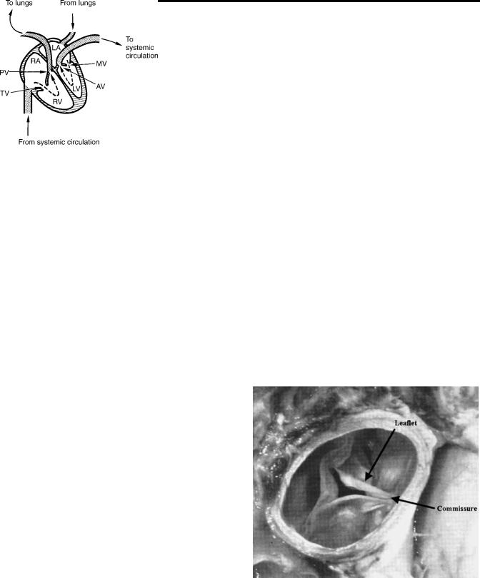
The human circulatory system provides adequate blood flow without interruption to the various organs and tissues and regulates blood supply to the demands of the body. The contracting heart supplies the energy required to maintain the blood flow through the vessels. The human heart consists of two pumps in series. The right side of the heart, a low pressure pump, consisting of the right atrium and the right ventricle supplies blood to the pulmonary circulation. The left side consisting of the left atrium and the left ventricle is the high pressure pump circulating blood through the systemic circulation. Figure 1 is a schematic representation of the four chambers of the heart and the arrows indicate the direction of blood flow. The pressure gradients developed between the main arteries supplying blood to the systemic and pulmonary circulation and the respective venous ends are the driving forces causing the blood flow and the energy is dissipated in the form of heat due to frictional resistance.
The four valves in the heart ensure that the blood flows only in one direction. The blood from the systemic circula-
tion supplies nutrients and oxygen to the cells for the various tissues and organs and removes carbon dioxide at the level of capillaries. The oxygen depleted blood returns through the systemic veins to the right atrium. During the ventricular relaxation or diastole, the blood passes through the tricuspid valve into the right ventricle. In the ventricular contraction phase of the cardiac cycle or systole, the tricuspid valve closes and the pulmonic valve opens to pump the blood to the lungs through the pulmonary arteries. Carbon dioxide is removed and oxygen is absorbed by the blood in the capillaries of the lungs that is surrounded by the alveolar sac with the air we breathe. The oxygen-rich blood returns to the left atrium via the pulmonary veins and passes through the mitral (bicuspid) valve into the left ventricle during the ventricular diastole. During the ventricular contraction, the mitral valve closes and the aortic valve opens to pump the blood through the systemic circulation. The main function of the heart valves is to control the direction of blood flow permitting flow in the forward direction and preventing regurgitation or back flow through the closed valves.
Anatomy of the Native Valves
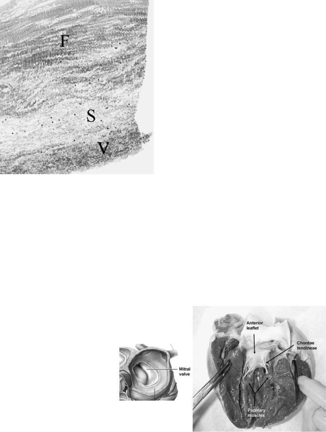
The aortic valve (Fig. 2) consists of three semicircular (semilunar) leaflets or cusps within a connective tissue sleeve (1) attached to a fibrous ring. The cusps meet at three commissures that are equally spaced along the circumference at the supraaortic ridge. This ridge is thickening of the aorta at which the cusps insert and there is no continuity of tissue from one cusp to the other across the commissure. The leaflet consists of three layers as shown in Fig. 3: the aortic side layer is termed the fibrosa and is the
Figure 1. Schematic of blood flow in the human heart. LA-Left atrium; RA-Right atrium; LV-Left ventricle; RV-Right ventricle; PV-pulmonary valve; TV-Tricuspid valve; AV-Aortic valve; and MV-Mitral valve.
Figure 2. Human aortic valve viewed from the aorta. (Adapted with permission from Otto, C. M. Valvular Heart Disease, Second Edition, 2004, Saunders/Elsevier, Inc., Philadelphia, PA.)
407
408 HEART VALVE PROSTHESES
Figure 3. A histologic section of an aortic valve leaflet depicting the three layers along the thickness of the leaflet: F ¼ Fibrosa; S ¼ Spongiosa; and V ¼ Ventricularis. (Courtesy of Prof. Michael Sacks of the University of Pittsburgh, Pittsburgh, PA.)
major fibrous layer within the body of the leaflet; layer on the ventricular side termed ventricularis is composed of both collagen and elastin; and the central portion of the valve termed the spongiosa consisting of loose connective tissue, proteins, and glycosaminoglycans (GAG). The leaflet length is larger than the radius of the annulus, and hence a small overlap of the tissue from each leaflet protrudes and forms a coaptation surface when the valve is closed to ensure that the valve is sealed in the closed position. The sinus of Valsalva is attached to the fibrous annular ring on the aortic side and is comprised of three
bulges at the root of the aorta. Each bulge is aligned with the belly or the central part of the valve leaflet. The left and the right sinuses contain the coronary ostia (openings) giving rise to the left and right coronary arteries, respectively, providing blood flow and nutrients to the cardiac muscles. When the valve is fully open, the leaflets extend to the upper edges of the sinuses. The anatomy of the pulmonic valve is similar to that of the aortic valve, but the sinuses in the pulmonary artery are smaller than the aortic sinuses, and the pulmonic valve orifice is slightly larger. The average aortic valve orifice area is 4.6 cm2 and is4.7 cm2 for the pulmonic valve (2). In the closed position, the pulmonic valve is subject to a pressure of 30 mmHg (3.99 kPa) while the load on the aortic valve is 100 mmHg (13.30 kPa).
The mitral and tricuspid valves are also anatomically similar with the mitral valve consisting of two main leaflets (cusps) compared to three for the valve in the right side of the heart. The valves consist of the annulus, leaflets, papillary muscles, and the chordae tendinae (Fig. 4). The average mitral and tricuspid valve orifice areas are 7.8 and 10.6 cm2, respectively (2). The atrial and ventricular walls are attached to the mitral annulus, consisting of dense collagenous tissue surrounded by muscle, at the base of the leaflets. The chordae tendinae are attached to the free edge of the leaflets at multiple locations and extend to the tip of the papillary muscles. Anterior and posterior leaflets of the mitral valve are actually one continuous tissue with two regularly spaced indentations called the commissures. The combined surface area of both the leaflets is approximately twice the area of the valve orifice and thus the leaflets coaptate during the valve closure. The posterior leaflet encircles two-thirds of the annulus and is quadrangular shaped, while the anterior leaflet is semilunar shaped. The left ventricle has two papillary muscles that attach to the ventricular free wall and tether the mitral valve in place via the chordae tendinae. This tethering prevents the leaflets from prolapsing into the left atrium during ventricular ejection. Improper tethering will result in the leaflets extending into the atrium and incomplete apposition of the leaflets will permit blood to
Figure 4. Schematic of the human mitral (bicuspid) valve and a photograph showing the anterior leaflet with the chordae tendinae attachment with papillary muscles. (Courtesy of Prof. Ajit Yoganathan from Georgia Institute of Technology.)

regurgitate back to the atrium. The tricuspid valve has three leaflets, a septal leaflet along with the anterior and posterior leaflets, and is larger and structurally more complicated than the mitral valve.
Valve Dynamics
At the beginning of systole, the left ventricle starts to contract and with the increase in pressure, the mitral valve closes preventing regurgitation of blood to the left atrium. During the isovolumic contraction with both the mitral and aortic valves closed, the ventricular pressure rises rapidly. The aortic valve opens when the left ventricular pressure exceeds the aortic pressure. The blood accelerates rapidly through the open valve and peak velocity of flow occurs during the first third of systole. The pressure difference between the left ventricle and the aorta required to open the valve is of the order of 1–2 mmHg (0.13–0.26 kPa). During the forward flow phase, vortices develop in the three sinuses behind the open leaflets and the formation of such vortices was first described by Leonardo da Vinci in 1513. Several studies have suggested that the vortices and the difference in pressure between the sinuses and the center of the aortic orifice pushes the leaflets toward closure even during the second third of systole when forward flow of blood continues. With the ventricular relaxation and rapid drop in the ventricular pressure, an adverse pressure gradient between the ventricle and the aorta moves the leaflets toward full closure with negligible regurgitation of blood from the aorta to the ventricle. Systole lasts for about one-third of the cardiac cycle and the peak pressure reached in the aorta during systole in healthy humans is 120 mmHg (15.96 kPa) and the diastolic pressure in the aorta with the aortic valve closed is80 mmHg (10.64 kPa).
At the beginning of diastole, the aortic valve closes and the ventricular pressure decreases rapidly during the isovolumic relaxation. As the ventricular pressure falls below the atrial pressure, the mitral valve opens and the blood flows from the atrium to the ventricle. The pressure difference between the left atrium and the ventricle required to open the mitral valve and drive the blood to fill the ventricle is smaller than that required with the aortic valve (< 1 mmHg or 0.13 kPa). As the blood fills the ventricle, vortical flow is established in the ventricle, and it has been suggested that the leaflets move toward closure due to the same. The atrial contraction induces additional flow of blood from the atrium into the ventricle during the second half of diastole and the adverse pressure gradient at the beginning of ventricular contraction forces the mitral valve to close and isovolumic contraction takes place. The chordae tendinae prevents the prolapse of the leaflets into the left atrium when the mitral valve is in the closed position. The dynamics of the mitral valve opening and closing is a complex process involving the leaflets, mitral orifice, chordae tendinae, and the papillary muscles. During systole, the closed mitral valve is subjected to pressures of 120 mmHg (15.96 kPa).
The dynamics of opening and closing of the pulmonic and the tricuspid valves are similar to the aortic and mitral valve, respectively, even though the pressures generated in
HEART VALVE PROSTHESES |
409 |
the right ventricle and the pulmonary artery are generally about a one-third of the corresponding magnitudes in the left side of the heart. From the description of the valve dynamics, one can observe several important features on the normal functioning of the heart valves. These include opening efficiently with minimal difference in pressure between the upstream and downstream sides of the valve, and efficient closure to ensure minimal regurgitation. In addition, the flow past the valves are laminar with minimal disturbances in flow and the fluid induced stresses do not activate or destroy the formed elements in blood such as the platelets and red blood cells. As the valves open and close, the leaflets undergo complex motion that includes large deformation, as well as bending. The leaflet material is also subjected to relatively high normal and shear stresses during these motions. The valves open and close at about once every second, and hence functions over several million cycles during the normal life of a human. These are some of the important considerations in the design and functional evaluation of heart valve prostheses that we consider in detail below.
Valvular Diseases and Replacement of the Diseased Valves
Valvular diseases are more common on the left heart due to the high pressure environment for the aortic and mitral valves and also with the tricuspid valve on the right side of the heart. Valvular diseases include stenosis and incompetence. Stenosis of the leaflets is due to calcification resulting in stiffer leaflets that will require higher pressures to open the valves. Rheumatic fever is known to affect the leaflets resulting in stenosed valves (3). Premature calcification of the bicuspid valve, as well as significant obstruction of the left ventricular outflow in congenital aortic valve stenosis, also affects the valves of the left heart
(3). Aortic sclerosis due to aging can also advance to valvular stenosis in some patients. Mitral stenosis may be the result of commissural fusion in younger patients and may also be due to cusp fibrosis. In the case of valvular stenosis, higher pressure needs to be generated to force the stiffer leaflets to open and the valvular orifice area in the fully open position may be significantly reduced. Effective orifice area (EOA) can be computed by the application of the Gorlin equation (4) based on the fluid mechanic principles and is given by the following relationship:
EOAðcm2Þ ¼ Qrms |
ð1Þ |
|
|
Cp |
|
|
Dp |
|
In this equation, Qrms is the root-mean-square (rms) flow rate (mL/s) during the forward flow through the valve and Dp is the mean pressure drop (mmHg) across the open valve. The measurement of mean pressure drop in vivo is described later, and the flow rate across the valve during the forward flow phase is computed from the measurement of cardiac output and the heart rate. The parameter C represents a constant that is based on the discharge coefficient used for the aortic or mitral valve, and the unit conversion factors to result in the computed area in terms of square centimeter. A more direct technique to estimate the effective orifice area is the application of conservation of mass principle. The systolic volume flow through the left
410 HEART VALVE PROSTHESES
ventricular outflow tract is determined as the product of the outflow tract cross-sectional area and the flow velocity– time integral. Since the same blood volume must also pass through the valve orifice, the valve orifice area is computed by dividing the volume flow with the measured aortic valve velocity–time integral (5). Replacement of the aortic valve is generally considered when the measured valvular orifice area is < 0.4 cm2 m 2 of body surface area (6). The corresponding value for the mitral stenosis is 1.0 cm2 m 2.
Valvular incompetence results from incomplete closure of the leaflets resulting in significant regurgitation of blood. Incompetence could be the result of decrease in leaflet area due to rheumatic disease or perforations in the leaflets due to bacterial endocarditis. Structural alterations due to loss of commissural support or aortic root dilatation can result in aortic valve incompetence. Rupture of chordae tendinae, leaflet perforation, and papillary muscle abnormality may also affect the mitral valve closure and increase in regurgitation. Optimal timing for valvular replacement in the case of native valve incompetence is not clearly defined.
Various methods for valvular reconstruction or repair are also being developed instead of replacement with prostheses since these techniques are associated with lower risk of mortality and lower risk of recurrence (7). Valvular repair rather than replacement is generally preferred for regurgitation due to segmental prolapse of the posterior mitral leaflet. Implantation of a prosthetic ring to reduce the size of the mitral orifice and improve leaflet coaptation is performed in the case of mitral regurgitation due to ring dilatation. Mitral endocarditis with valvular or chordal lesions is also repaired rather than replacing the whole valve. Dilatation of the root and prolapse of the cusps are also the most important causes for regurgitation of the aortic valves and several techniques have also been developed to correct these pathologies (7).
The cardiopulmonary bypass technique to reroute the blood from the vena cava to the ascending aorta, and the introduction of cold potassium cardioplegia to arrest the heart to perform open heart surgery introduced in the 1950s enabled the replacement of diseased valves. Replacement of severely stenosed and/or incompetent valves with prostheses is a common treatment modality today and patients with prosthetic valves lead a relatively normal life. Yet, significant problems are also encountered with implanted prosthetic valves and efforts are continuing to improve the design of the valves for enhanced functionality and minimizing the problems encountered with implantation.
PROSTHETIC HEART VALVES
Ideal Valve Design
An ideal valve to be used as replacement for a diseased valve should mimic the functional characteristics of the native human heart valves with the following characteristics (adapted from Ref. 8). The prosthetic valve should open efficiently with a minimal transvalvular pressure drop. The blood should flow through the orifice with central and undisturbed flow as is observed with healthy native
heart valves. The valve should close efficiently with minimal amount of regurgitation. The material used for the valve should be biocompatible, durable, nontoxic, and nonthrombogenic. The valve will be anticipated to open and close for > 40 million cycles/year for many years and must maintain the structural integrity throughout the lifetime of the implant. Blood is a corrosive and chemically unstable fluid that tends to form thrombus in the presence of foreign bodies. To avoid thrombus formation, the valve surfaces must be smooth, and the flow past the valve should avoid regions of stagnation and recirculation as well as minimize flow-induced stresses that are factors related to thrombus initiation. The prosthetic valve should be surgically implantable with ease and should not interfere with the normal anatomy and function of the cardiac structures and the aorta. The valve should be easily manufactured in a range of sizes, inexpensive, and sterilizable.
Transplanting freshly explanted human heart valves from donors who died of noncardiovascular diseases is probably the most ideal replacement and such homograft valves have been successfully used as replacements. These are the only valves entirely consisting of fresh biological tissue and sewn into place resulting in an unobstructed central flow. The transplanted homograft valves are no longer living tissue, and hence lack the cellular regeneration capability of the normal valve leaflets. Thus, the transplanted valves are vulnerable to deterioration on a long-term use. Moreover, homograft valves are difficult to obtain except in trauma centers in large population areas, and hence not a viable option generally.
Numerous prosthetic valves have been developed over the past 40 years and most of the design and development of valvular prostheses have been empirical. The currently available heart valve prostheses can be broadly classified into two categories: mechanical heart valves (MHV) and bioprosthetic heart valves (BHV). Even though valves from both categories are routinely implanted in patients with valvular disease and the patients with prosthetic implants lead a relatively normal life, several major problems are encountered with the mechanical and biological prosthetic valves (9). These problems include: (1) thromboembolic complications; (2) mechanical failure due to fatigue or chemical changes; (3) mechanical damage to the formed elements in blood including hemolysis, activation, and destruction of platelets and protein denaturation; (4) perivalvular leak due to healing defects; (5) infection; and (6) tissue overgrowth. The first three problems with implanted valves can be directly attributed to the design of the mechanical and biological prostheses and the fluid and solid mechanics during valve function. Thrombus deposition on the valvular surface and subsequent breakage of the thrombus to form emboli that can result in stroke or heart failure is still a major problem with MHV implants. Hence, patients with MHV implants need a long-term anticoagulant therapy that can lead to complications with bleeding. On the other hand, patients implanted with bioprostheses do not generally require anticoagulant therapy except immediately after surgery. Yet, leaflet tearing with structural disintegration results in the need for BHV implants to be replaced at about 10–12 years after implantation on the average. Due to the necessity of multiple
surgeries during a lifetime, the tissue valves are generally not implanted in younger patients. Patients who cannot tolerate or cannot be on long-term anticoagulant therapy are also candidates for the BHV.
Mortality is higher among patients after prosthetic valve replacement than among age-matched controls. Mortality rate is not significantly different between MHV and BHV implantation. In addition to the mortality rate and valve related morbidity, quality of life for the patient must be an important consideration in the choice of valve implantation and the quality of life is difficult to quantify. Individual patients may place different emphasis on mortality, freedom from reoperation, risk of thromboembolism and stroke, risk of anticoagulation-related hemorrhage, and lifestyle modification required with chronic anticoagulation. Patients may choose to accept the high probability of reoperation within 10–12 years with BHV in order to avoid long-term anticoagulation with MHV, whereas others may want to avoid the likelihood of reoperation (10).
We will review the historical development of heart valve prostheses, functional evaluation of these valves in order to understand the relationship between the dynamics of the valve and the problems associated with the valve implants and our continuing efforts on the understanding of the problem and improvements in design.
Mechanical Heart Valves
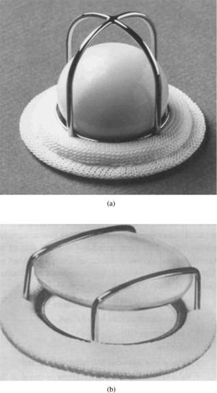
Mechanical valves are made of blood compatible, nonbiological material, such as metals, ceramics, or polymers. The initial designs of mechanical valve prostheses were of the centrally occluding type with either a ball or disk employed as the moving occluder. The occluder passively responds to the difference in pressure in opening and closing of the valves. Starr-Edwards caged ball valve (Fig. 5a) was the first mechanical valve to be implanted in 1960 in the correct anatomical position as replacement for the diseased native mitral valve (11–14). The caged disk prostheses (Fig. 5b), in which a flat disk was employed as the occluder, were of a lower profile than the ball valves, and hence were thought to be advantageous especially as a replacement in the mitral position in order to minimize interference with the cardiac structures. However, increased flow separation and turbulence in the flow past the flat disk compared to that for the spherical ball occluder in the caged ball prostheses resulted in larger pressure drop across the valve with the caged disk design. An increased propensity for thrombus deposition in the recirculation region was also observed, and hence this design was not successful in spite of the low profile. The cage in the caged ball prostheses is made of a polished cobalt–chromium alloy and the ball is made of a silicone rubber that contains 2% by weight barium sulfate for radiopacity. The sewing ring contains silicone rubber insert under knitted composite polytetrafluoroethylene (PTFE: Teflon) and polypropylene cloth. With the centrally occluding design, the flow dynamics past the caged ball prostheses is vastly different from that of flow past native aortic or mitral valves.
Within the next two decades of 1970s and 1980s, valve prostheses with a tilting disk or bileaflet designs were introduced with significantly improved flow characteris-
HEART VALVE PROSTHESES |
411 |
Figure 5. Photographs of (a) Starr-Edwards caged ball valve (Edwards Lifesciences, LLC, Irvine, CA); and (b) a caged disk valve (Courtesy of Prof. Ajit Yoganathan of Georgia Institute of Technology, Atlanta, GA) as examples of early mechanical valve designs.
tics. The first tilting disk valve that was clinically used was a notched Teflon occluder that engaged in another pair of notches in the housing (15). The stepped occluder with the notches was not free to rotate. Clinical data soon indicated severe thrombus formation around the notches and wear of the Teflon disk leading to severe valvular regurgitation or disk embolization (16). A major improvement to this design was the introduction of hinge-less free-floating tilting disk valves in the Bjork–Shiley (17) and the Lillehei–Kaster valves. The Bjork–Shiley valve had a depression in the disk and two welded wire struts in the valve housing to retain the disk. The occluder tilted to the open and closed position and it was free to rotate around its center. The Bjork– Shiley valve housing was made from Stellite-21 with a Teflon sewing ring and a Delrin disk. Compared to the

412 HEART VALVE PROSTHESES
Figure 6. Tilting disk mechanical valve prostheses: (a) Bjork– Shiley valve; (b) Medtronic Hall valve (Medtronic, Inc., Minneapolis, MN; (c) Omni Carbon valve (MedicalCV Inc., Minneapolis, MN);
(d) Sorin valve (Sorin Biomedica Cardio S.p.A., Via Crescentino, Italy).
centrally occluding caged ball valves, a large annulus diameter compared to the tissue annulus diameter in the tilting disk valve resulted in a very low pressure drop and thus energy loss in the flow across the valve in the open position. The disk opened to an angle of 608 or more, and hence the flow was more central. The free floating disk that rotated during the opening and closing phases prevented any build up of thrombus. However, the Delrin disk had a propensity for swelling during autoclaving that may compromise the proper functioning of the leaflets (18,19). The disk for the Lillehei–Kaster valve consisted of a graphite substrate coated with a 250 mm thick layer of a carbon– silicon alloy (Pyrolite). The pyrolytic carbon has proven to be a very durable and blood-compatible material for use in prosthetic heart valves and is the preferred material for the MHVs currently available for implants. The Bjork– Shiley valve also had the Delrin disk replaced with pyrolytic carbon disk shortly thereafter (Fig. 6a). The Medtronic Hall tilting disk valve (Fig. 6b) has a central, disk control strut. An aperture in the flat pyrolytic carbon disk affixes it to this central guiding strut and allows it to move downstream by 2.0 mm. This translation improves the flow velocity between the orifice ring and the rim of the disk. The ring and strut combination is machined from a single piece of titanium for durability and the housing can be rotated within the knitted Teflon sewing ring for optimal orientation of the valve within the tissue annulus. The Omniscience valve was an evolution of the Lillehei–Kaster valve and the Omnicarbon valve (Fig. 6c) is the only tilting disk valve with the occluder and housing made of pyrolytic carbon. Sorin Carbocast tilting disk valve (Fig. 6d), made in Italy and available in countries outside United States, has the struts and the housing made in a single piece by a microcast process and thus eliminates the need for welding the struts to the housing. The cage for this valve is made of a chrome–cobalt alloy and coated with a carbon film. The
tilting disk valves of the various manufacturers open to a range of angles varying from 60 to 858 and in the fully open position, the flow passes through the major and minor orifices. Some of the valve designs, such as the Bjork– Shiley valve, encountered unforeseen problems with structural failure due to further design modifications, and hence are currently not used for replacement of diseased native heart valves. However, some of these designs are still being used in the development of artificial heart and positive displacement left ventricular assist devices.
Another major change in the MHV design was the introduction of a bileaflet valve in the late 1970s. The St. Jude Medical bileaflet valve (Fig. 7a) incorporates two semicircular hinged pyrolytic carbon leaflets that open to an angle of 858 and the design is intended to provide minimal disturbance to flow. The housing and the leaflets of the bileaflet valve is made of pyrolytic carbon. Numerous other bileaflet designs have since been introduced into the market. Several design improvements have also been incorporated in the bileaflet valve models in order to improve their hemodynamic performance. The design improvements have included a decrease in thickness of the sewing cuff that allows the placement of a larger
Figure 7. Bileaflet mechanical valve prostheses: (a) St. Jude valve (St. Jude Medical, Inc., St. Paul, MN); (b) Carbomedics valve (Carbomedics Inc., Austin Texas); (c) ATS valve (ATS Medical Inc., Minneapolis, MN); (d) On-X valve (Medical Carbon Research Institute, LLC, Austin, Texas); and (e) Sorin valve (Sorin Biomedica Cardio S.p.A., Via Crescentino, Italy).

housing within the cuff for a given tissue annulus diameter with the resulting hemodynamic improvement. Structural reinforcement of the housing has also allowed reducing its thickness that increases the internal orifice area for improved hemodynamics. The Carbomedics bileaflet valve (Fig. 7b) was introduced into the market in the 1990s with a recessed pivot design. The aortic version of this valve is designed to be implanted in the supraannular position enabling a larger size valve to be implanted with respect to the aortic annulus. More recent bileaflet valve designs available in the market include the ATS valve (Fig. 7c) with an open leaflet stop rather than the recessed hinges and the On-X bileaflet valve (Fig. 7d) that has a length to diameter ratio close to the native heart valves, a smoothed pivot recess allowing for the leaflet to open to 908, a flared inlet for reducing flow disturbances, and a two point landing mechanism for smoother closing of the leaflets. The Sorin Bicarbon valve (Fig. 7e), marketed outside the United States, has curved leaflets, and hence increases the area of the central orifice. The pivots of this valve with two spherical surfaces enable the leaflet projections to roll against the surfaces rather than with the sliding action between the leaflet and the housing at the hinges.
Studies have shown that the bileaflet valves generally have a smaller pressure drop compared to the tilting disk valves, especially in the smaller sizes. However, there are several characteristic differences between the bileaflet and tilting disk valve designs that must be noted. The bileaflet valve designs include a hinge mechanism generally by introducing a recess in the housing in which a protrusion from the leaflets interacts during the opening and closing of the leaflets, or open pivots for the retention of the leaflets. On the other hand, the tilting disk valve designs do not have a hinge mechanism for retaining the occluder and the occluder is freefloating. The free-floating disk rotates as the valve opens and closes, and hence the stresses are distributed around the leaflets as opposed to the bileaflet designs. In spite of the advances in the MHV valves by the introduction of the tilting disk and bileaflet designs, design improvements aimed at enhancing the flow dynamics, and material selection, problems with thromboembolic complications and associated problems with bleeding (20) are still significant with the implanted valves and the possible relationship between the flow dynamics and initiation of thrombus will be discussed in detail later. An example of thrombus deposition and tissue ingrowth with an explanted MHV is shown in Fig. 8.
Bioprosthetic Valves
With the lack of availability of homograft valves as replacement of diseased valves, and as alternative to MHV that required long-term anticoagulant therapy, numerous attempts have been made in the use of various biological tissues as valvular replacement material. BHV made out of fascia lata (a layer of membrane that encases the thigh muscles) as well as human duramater tissue has been attempted. Fascia lata tissue was prone to deterioration, and hence unsuitable while the duramater tissue suffered from lack of availability for commercial manufacture in sufficient quantities. Harvested and preserved porcine
HEART VALVE PROSTHESES |
413 |
Figure 8. Photograph of an explanted mechanical heart valve prosthesis with thrombus deposition on the leaflet surface and tissue ingrowth (Courtesy of Prof. Ajit Yoganathan of Georgia Institute of Technology, Atlanta, GA.)
aortic valve as well as BHV made of bovine pericardial tissue have been employed as replacement and have been available commercially for > 30 years. The early clinical use of a xenograft (valve made from animal tissue) employed treatment of the leaflets with organic mercurial salts (21) or formaldehyde (22) to overcome the problems of rejection of foreign tissue by the body. Formaldehyde is used to fix and preserve the tissue in the excised state by histologists and results in shrinkage as well as stiffening of the tissue. Formaldehyde treated valves suffered from durability problems with 60% failure rates at 2 years after implantation. Subsequently, it was determined that the durability of the tissue cross-links was important in maintaining the structural integrity of the leaflets and gluteraldehyde was employed as the preservation fluid (23). Glutaraldehyde also reduces the antigenicity of the foreign tissue, and hence can be implanted without significant immunological reaction.
Porcine aortic valves are excised from pigs with the aortic root and shipped to the manufacturer in chilled saline solution. Support stents, configured as three upright wide posts with a circular base, is manufactured out of metal or plastic material in various sizes and covered in a fabric. A sewing flange or ring is attached to the base of the covered stent and used to suture the prostheses in place during implantation. The valve is cleaned, trimmed, fitted, and sewn to the appropriate size cloth covered stent. The stented valve is fixed in gluteraldehyde with the valve in the closed position. Glutaraldehyde solution with concentrations ranging from 0.2 to 0.625% is used in the fixation process at pressures of < 4 mmHg (0.53 kPa) to maintain the valve in the closed position. The low pressure fixation maintains the microstructure of collagen. The first glutar- aldehyde-treated porcine aortic valve prosthesis mounted on metallic stent was implanted in 1969 (24). The metallic frame was soon replaced by a flexible stent on a rigid base ring; the Hancock Porcine Xenograft was commercially introduced in 1970. The stent in this valve is made of polypropylene with stainless steel radiopaque marker,
414 HEART VALVE PROSTHESES
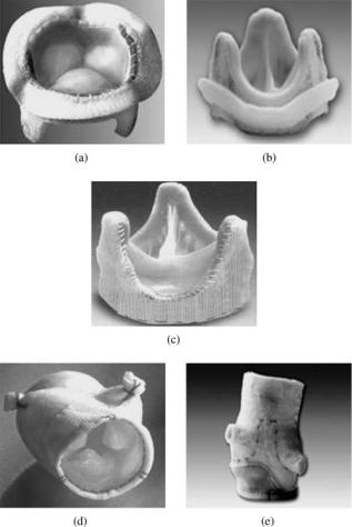
Figure 9. Porcine bioprosthetic valve prostheses: (a) Hancock II valve (Medtronic Inc., Minneapolis, MN); (b) Carpentier–Edwards valve (Edwards Lifesciences, LLC, Irvine, CA); (c) Toronto stentless valve (St. Jude Medical, Inc., St. Paul, MN); (d) Medtronic Freestyle stentless valve (Medtronic Inc., Minneapolis, MN); and
(e) Edwards Prima Plus stentless valve (Edwards Lifesciences, LLC, Irvine, CA).
sewing ring made of silicone rubber foam fiber and polyester used as the cloth covering. Hancock Modified Orifice valve (Fig. 9a) was introduced in 1977 as a refinement of the earlier valve. The right coronary cusp of the pig’s aortic valve is a continuation of the septal muscle, and hence stiffer. In the modified orifice valve, the right coronary cusp is replaced with a non-coronary cusp of comparable size from another valve. The Carpentier–Edwards Porcine valve (Fig. 9b) also employs a totally flexible support frame. The Hancock II and the Carpentier–Edwards supra-annu- lar porcine bioprostheses employed modified preservation techniques in which the porcine tissue is initially fixed at 1.5 mmHg (0.2 kPa), and then at high pressure in order to improve the preservation of the valve geometry. The supraannular valve is designed to be implanted on top of the aortic annulus while aligning the internal diameter of the valve to the patient’s annulus and this technique allows implantation of a larger valve for any given annular size. These valves are also treated with antimineralization
solution such as sodium dodecyl sulfate (SDS) in order to reduce calcification.
Another major innovation in the bioprosthetic valve design was the introduction of stentless bioprostheses. In the stented bioprostheses, the regions of stress concentration are observed at the leaflet–stent junction and the stentless valve design is intended to avoid such regions prone to failure. The absence of the supporting stents also results in less obstruction to flow, and hence should improve the hemodynamics across the valves. Due to the lack of stents, larger size valve can be implanted for a given aortic orifice to improve the hemodynamics. Stentless porcine bioprostheses are only approved for aortic valve replacement in the United States. In vitro studies have shown improved hemodynamic performance with the stentless designs in the mitral position, but questions remain about the durability of these valves, and the implantation techniques are also complex in the mitral position. Examples of stentless bioprostheses currently available in the United States include: St. Jude Medical Toronto SPV (Fig. 9c); Medtronic Freestyle (Fig. 9d); and Edwards Prima (Fig. 9e) valves. The Edwards Prima prosthesis is the pig’s aortic valve with a preserved aortic root, with a woven polyester cloth sewn around the inflow opening to provide additional support and with features that make it easier to implant. The other stentless valve designs are also porcine aortic valves with the intact aortic root and specific preservation techniques in order to improve the hemodynamic characteristics and durability after implantation. In the Toronto SPV valve, a polyester cloth covering around the prosthesis separates the xenograft from the aortic wall of the host, making it easier for handling and suturing, and also promotes tissue ingrowth.
Both stented and stentless porcine tissue valves are from the pig’s native aortic valve, and hence individual leaflets need not be manufactured. In order to have sufficient quantities of these valves in various sizes available for implant, a facility to harvest adequate quantities of these valves become necessary. As an alternative, pericardial valves are made by forming the three leaflets from the bovine pericardial tissue, and hence valves of various sizes can be made. In the pericardial valves, bovine pericardial sac is harvested and shipped in chilled saline solution. At the manufacturing site, the tissue is debrided of fatty deposits and trimmed to remove nonusable areas before the tissue is fixed in glutaraldehyde. After fixation, leaflets are cut out from the selected areas of the pericardial tissue and sewn to the cloth-covered stent in such a fashion to obtain coapting and fully sealing cusps. Since the valve is made in the shape of the native human aortic valve, the hemodynamic characteristics were also superior to the porcine valves in comparable sizes. The Ionescu-Shiley pericardial valve introduced into the market in the 1970s was discontinued within a decade due to problems associated with calcification and decreased durability. For this reason, pericardial valve were not marketed by the valve companies for several years. With advances in tissue processing and valve manufacturing technology, pericardial valves were reintroduced into the commercial market in the 1990s. The Edwards Lifesciences introduced the Carpentier-Edwards PERIMOUNT Bioprostheses
Figure 10. Pericardial bioprosthetic valve prostheses: (a) Carpentier-Edwards valve (Edwards Lifesciences, LLC, Irvine, CA), (b) Sorin Pericarbon valve (Sorin Biomedica Cardio S.p.A., Via Crescentino, Italy); (c) Sorin Pericarbon stentless valve (Sorin Biomedica Cardio S.p.A., Via Crescentino, Italy); and (d) Mitroflow Aortic pericardial valve (Sorin Group Canada, Inc., Mitroflow Division, Burnaby, B.C., Canada.)
(Fig. 10a) in the early 1990s. The pericardial tissue in this valve is mounted on a lightweight frame that is covered with porous, knitted PTFE material. A sewing ring made of molded silicone rubber covered with PTFE cloth is incorporated to suture the valve in place. Sorin pericardial valve (Fig. 10b), Sorin stentless pericardial valve (Fig. 10c) and the Mitroflow aortic pericardial valve (Fig. 10d) are available in markets outside the United States.
FUNCTIONAL CHARACTERISTICS
From the functional point of view, the implanted valve prostheses should open with minimal transvalvular pressure drop and have minimal energy loss in blood flow across the valve, and the valve must close efficiently with minimal regurgitation. The valve should mimic the central flow characteristics that are observed with native human heart valves with minimally induced fluid dynamic stresses on the formed elements in blood. The flow characteristics across the implants should also avoid regions of stasis or flow stagnation where thrombus deposition and growth can be enhanced. In vivo measurements, in vitro experimental studies, and computational simulations have been used over the past 40 years in order to assess the functional characteristics of the mechanical and bioprosthetic heart valves. The information gained from such studies have been exploited to improve the design of the valves in order to improve the performance characteristics of the valves and also increase the durability in order to provide a ‘‘normal’’ life style for the patient with prosthetic valve implants.
HEART VALVE PROSTHESES |
415 |
Pressure Drop and Effective Orifice Area
In vivo measurement of pressure drop requires placing pressure transducers inserted via a catheter both on the inflow and outflow side of the valve, and computing the pressure drop during the phase when the valve is open. For the aortic valve, the pressure transducers are placed in the left ventricular outflow tract and in the ascending aorta. The peak or the average pressure drop during the forward flow phase is computed from the recorded data. To avoid the invasive technique of catheterization, the fluid mechanics principle can also be applied to estimate the pressure drop across the valve in the aortic position. The average velocity, V in m s 1, in the ascending aortic crosssection is measured noninvasively and the pressure drop, Dp expressed in millimeters of mercury can be computed using the equation
Dp 4V2 |
ð2Þ |
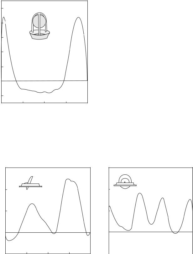
Using this simplified equation and noninvasive measurement of the aortic root velocity using the Doppler technique, the pressure drop across the aortic valve can be computed. With the availability of several designs of MHV and BHV, it is desirable to compare the pressure drop and regurgitation for the various valve designs. In the case of development of a new valve design, United States Federal Drug Administration (FDA) requires that these quantities measured in vitro for the new designs are compared with currently approved valves in the market. In vitro comparisons are performed in pulse duplicators that mimic the physiological pulsatile flow in the human circulation. One of the initial designs of a pulse duplicator for valve testing was that of Wieting (25) that consisted of a closed-loop flow system that is actuated by a pneumatic pump to initiate pulsatile flow through the mitral and aortic valves in their respective flow chambers. Pressure transducers were inserted through taps in the flow chambers on the inflow and outflow sides to measure the pressure drop across the valves. The fluid used in such in vitro experimental studies, referred to as the blood-analogue fluid, is designed to replicate the density (1060 kg m 3) and viscosity coefficient (0.035 P or 35 10 4 Pa s) of whole human blood. A glycerol solution (35–40% glycerin in water) has been generally used as the blood analog fluid in these studies. Prosthetic valves are made in various sizes (specified in sewing ring diameter magnitude). In comparing the pressure drop data for the various valve designs, proper comparison can be made on data only with comparable valve sizes. Since the flow across the valve during the forward flow phase is not laminar, the pressure drop has a nonlinear relationship with flow rate. Hence, pressure drop is measured for a range of flow rates and the pressure drop data is presented as a function of flow rate. Numerous studies comparing the pressure drop data for the various mechanical and bioprosthetic valves have been reported in the literature. Typical pressure drop comparisons for MHV and BHV (of nominal size of 25 mm) are shown in Fig. 11 (14). As can be observed, stented porcine tissue valves have the higher pressure drop, and hence are considered to be stenotic, especially in smaller valve sizes. The advantage of the stentless bioprostheses design is

416 HEART VALVE PROSTHESES
30
|
|
|
|
|
|
|
Bileaflet valve |
|||
|
|
|
|
|
|
|
||||
|
|
|
|
|
|
|
Tilting disk valve |
|||
|
|
|
|
|
|
|
Porcine valve |
|||
|
|
|
|
|
|
|
||||
Hg) |
20 |
|
|
|
|
|
Pericardial valve |
|||
|
|
|
|
|
||||||
|
|
|
|
|
Stentless valve |
|||||
|
|
|
|
|
||||||
difference (mm |
|
|
|
|
|
|
||||
|
|
|
|
|
|
|
|
|
|
|
Pressure |
10 |
|
|
|
|
|
|
|
|
|
|
|
|
|
|
|
|
|
|
|
|
|
|
|
|
|
|
|
|
|
|
|
|
|
|
|
|
|
|
|
|
|
|
|
|
|
|
|
|
|
|
|
|
|
|
|
|
|
|
|
|
|
|
|
|
|
|
|
|
|
|
|
|
|
|
|
|
|
|
|
|
|
|
|
|
|
|
|
|
|
|
|
|
|
|
|
|
|
|
|
|
|
|
|
|
|
|
|
|
|
|
|
|
|
|
|
|
|
|
|
|
|
|
|
|
|
|
|
|
|
|
|
|
|
|
|
|
|
|
|
|
|
|
|
|
|
|
|
|
|
|
|
|
0
200 |
300 |
400 |
|
Flow rate (cm3/s) |
|
Figure 11. Typical plots for the pressure drop as a function of flow rate for the various mechanical and bioprosthetic valve prostheses (Courtesy of Prof. Ajit Yoganathan of Georgia Institute of Technology, Atlanta, GA.)
obvious especially in smaller sizes since the flow orifice will be larger due to the absence of supporting stents. Supraannular design also permits the implantation of a larger sized valve for a given annulus orifice, thus providing a smaller pressure drop and energy loss. Smaller pressure drops across the valve prostheses will result in a reduced workload of the left ventricle as the pump. Gorlin equation, described in Eq. 1, has also been employed to compute the effective orifice area for the various valve designs (14). Generally, the pericardial and bileaflet valve designs have the largest effective orifice area, followed by the tilting disk, and porcine valves, with the caged ball valve exhibiting the smallest effective orifice area for a given sewing ring diameter. Valves with the larger EOA correspond to a smaller pressure drop and energy loss in flow across the valve. Performance index (PI), computed as the ratio of effective orifice area to the sewing ring area is also used for comparison of the various valve designs. Table 1 includes data on the EOA and PI for the various MHV and BHV with a 27 mm tissue annulus diameter from in vitro experimental studies. It can be observed that the centrally occluding caged ball valve and stented porcine valves have lower values of PI where as the tilting disk, bileaflet, pericardial valves, and stentless tissue valves have higher values indicating improved hemodynamics for the same values of the tissue annulus diameter.
Regurgitation
In discussing the flow dynamics with native heart valves, it was observed that the anatomy and the fluid dynamics enable the leaflets to close efficiently with minimal amount
|
400 |
|
|
Systole |
|
|
|
|
|
|
|
Diastole |
|
|
|
|
|
|
|
|
|
|
|
|
|
|
|
|
|
|
|||
|
|
|
|
|
|
|
|
|
|
|
|
|
|
|
|
|
|
300 |
|
|
|
|
|
|
|
|
|
|
|
|
|
|
|
|
|
|
|
|
|
|
|
|
|
|
|
|
|
|
|
|
(mL/s) |
200 |
|
|
|
|
|
|
|
|
Valve |
|
|
|
|
||
|
|
|
|
|
|
|
|
|
|
|
|
|||||
|
|
|
|
|
|
|
|
|
|
|
|
|
||||
|
|
|
|
|
|
|
|
|
|
|
|
|
|
|||
|
100 |
|
|
|
|
|
|
|
|
closing |
|
Static |
|
|
||
rate |
|
|
|
|
|
|
|
|
|
|
|
|
|
|
||
|
|
|
|
|
|
|
|
|
|
|
|
|
leakage |
|
|
|
Flow |
|
|
|
|
|
|
|
|
|
|
|
|
|
|
|
|
0 |
|
|
|
|
|
|
|
|
|
|
|
|
|
|
|
|
|
|
|
|
|
|
|
|
|
|
|
|
|
|
|
|
|
|
−100 |
|
|
Valve |
|
|
|
|
|
|
Closing |
|
|
|
|
|
|
|
|
|
|
|
|
|
|
leakage |
|
|
|
|
|||
|
|
|
|
|
|
|
|
|
|
|
|
|||||
|
|
|
|
opening |
|
|
|
|
|
|
|
|
|
|
|
|
|
−200 |
|
|
|
|
|
|
|
|
|
|
|
|
|
|
|
|
|
|
|
|
|
|
|
|
|
|
|
|
|
|
||
|
−300 |
0.2 |
|
0.4 |
|
|
0.6 |
0.8 |
1 |
|||||||
|
0 |
|
|
|
||||||||||||
Time (s)
Figure 12. Flow rate across mechanical valve prosthesis in the aortic position obtained in a pulse duplicator in vitro measured with an electromagnetic flow meter.
of regurgitation. On the other hand, the adverse pressure gradient at the end of the forward flow motion induces the occluders to move toward closure and all prosthetic valves exhibit a finite amount of regurgitation. Figure 12 shows a typical flow rate versus time curve obtained from an electromagnetic flow meter recording obtained in vitro in a pulse duplicator with a mechanical valve in the aortic position. As can be observed, a certain volume of reverse flow is observed as the valve closes and is termed as closing leakage. The closing leakage is related to the geometry of the valve and the closing dynamics. The rigid occluders in the mechanical valves also prevent the formation of a tight seal between the occluder and the seating ring when the valve is closed. With the tilting disk and bileaflet valves, a small gap between the leaflet edge and the valve housing is also introduced in order to provide a continuous wash-out of blood in the hope of preventing any thrombus deposition. Hence, even when the valve is fully closed, a small volume of blood is continuously leaking and is termed the static leakage. Percent regurgitation is defined as the ratio of the leakage volume over the net forward flow volume expressed as a percentage. Percent regurgitation can be computed by recording the flow rate versus time curve in an in vitro experimental set up and measuring the area under the forward and reverse flow phases from the data. These can be compared for the various size valves of the same model and also for comparison across the various valve models. Table 1 shows typical data of regurgitant volumes measured in vitro under physiological pulsatile flow in a pulse duplicator. The BHV designs result in more efficient leaflet closure with relatively small regurgitant volumes followed by the caged ball valve design. The magnitudes of the regurgitant volumes for the tilting disk and bileaflet valves are relatively larger and comparable to each other.
Quantitative measurement of percent regurgitation in vivo with both incompetent native valves or with prostheses has not been successful, even though attempts have

HEART VALVE PROSTHESES |
417 |
Table 1. Comparison of Effective Orifice Area (EOA)a, Performance Index (PI), Regurgitation Volume, and Peak Turbulent Shear Stresses for the Various Models of Commercially Available Valve Prostheses
Valve Type |
EOAb cm2 |
PI |
Reg. Vol., cm3/beat |
Peak Turb. SS, Pac |
|
|
|
|
|
Caged ball |
1.75 |
0.30 |
5.5 |
185 |
Tilting Diskd |
3.49 |
0.61 |
9.4 |
180 |
Bileafletd |
3.92 |
0.68 |
9.15 |
194 |
Porcine (Stented)d |
2.30 |
0.40 |
< 2 |
298 |
Pericardial (Stented)d |
3.70 |
0.64 |
< 3 |
100 |
Stentless BHV |
3.75 |
0.65 |
< 4 |
NAe |
aEOA ¼ Effective orifice area computed by the application of Gorlin’s equation (4). bValues compiled from Yoganathan (14).
cTurbulent stresses were measured at variable distances from the valve seat.
dValues reported are mean values from several valve models of the same type. Data reported are for 27-mm tissue annulus diameter size of the valves with measurements obtained in vitro in a pulse duplicator with the heart rate of 70 bpm and a cardiac output of 5.0 L min 1.
eNot available ¼ NA.
been made to employ fluid mechanical theories for regurgitant flow in order to estimate the leakage volume. Turbulent jet theory and proximal flow convergence theory have been employed in an attempt to measure the regurgitant glow volume quantitatively (26,27). However, in vivo application has not been successful due to the restrictive assumptions of steady flow and alterations due to impingement of the jet on the ventricular wall in the theoretical considerations as well as lack of in vivo validation.
Dynamics of Valve Function
As discussed earlier, significant problems still exist with the implantation of heart valve prostheses in patients with disease of native heart valves. These include thrombus initiation and subsequent embolic complications with MHV implantation. The thromboembolic rates with MHV have been estimated at 2%/patient year (28). Structural disintegration and tearing of leaflets are the major complications with BHV requiring reoperation in 10–12 years after implantation. Flow past healthy native valves are central with minimal flow disturbances and fluid induced stresses and it can be anticipated that the fluid dynamics past the mechanical valve prostheses will be drastically different from those of native heart valves. Flow induced stresses with MHV function have long been implicated with hemolysis and activation of platelets that may trigger thrombus initiation. Regions of stress concentration on the leaflets during the opening and closing phases have been implicated on structural alterations of collagen fibers resulting in leaflet tears with BHV. Detailed functional analysis of implanted valve prostheses in vivo is impractical. Limited attempts have been made in the measurement of velocity profiles distal to the valve prostheses in the aortic position with hot film anemometry (29). Doppler and MR phased velocity mapping techniques have also been used to measure the velocity profiles distal to heart valves (30–32). However, detailed velocity measurements very close to the leaflets and housing of prosthetic valves are not possible in vivo, and hence in vitro experimental studies and computational fluid dynamic simulation are necessary for the same. Limited in vivo studies in animal models have also been employed to describe the complex leaflet motion with native aortic valves (33–37). In vitro studies and computer simulations are also necessary for a
detailed analysis of stress distribution in the leaflets of native valves and bioprostheses during the opening and closing phases of the valve function and to determine its relationship with failure of the leaflets.
Flow Dynamics Past Mechanical Valves
With the assumption that the deposition of thrombi in MHV implants is related to the flow induced stresses, studies are continuing to date on the deterministic relationship between fluid induced stresses and damage to formed elements in blood. Subjecting blood cells to precise flow fields and assessing the destruction or activation (of platelets), magnitudes of turbulent stresses beyond which damage can be expected has been established. In addition to the magnitude of the flow induced stresses, the time for which the blood elements are exposed to the stresses also need to be considered in assessing the destruction or activation of the platelets. Nevaril et al. (38) reported that blood cells can be hemolyzed with shear stresses of the order of 150–400 Pa. In the presence of foreign surfaces, the threshold for red blood cell damage reduces to 1–10 Pa (39). Sublethal damage to red blood cells have also been reported at turbulent shear stress levels of about 50 Pa (40). Shear induced platelet activation and aggregation is observed to be a function of both magnitude and duration of shear stresses. The larger the magnitude of the shear stress, the shorter is the duration to which platelets are subjected to the shear before they get activated. Platelets have been shown to be activated with 10–50 Pa of shear stresses with a duration of the order of 300 ms (41). Platelet damage also increases linearly with time of exposure when subjected to constant magnitudes of shear (42).
Hence, it is of interest to determine the level of wall shear and turbulent shear stresses in flow past valve prostheses as factors causing initiation and deposition of thrombus.
For the first two to three decades after the implantation of the first mechanical valve, investigations concentrated on the flow dynamics past the valves during the forward flow phase and measurements of velocity profiles, regions of stasis and recirculation, high wall shear and bulk turbulent shear stresses. Wieting (25) employed a pulse duplicator and flow visualization studies using illuminated neutrally buoyant particles in order to qualitatively describe the nature of flow past the prosthetic valves.
418 HEART VALVE PROSTHESES
|
125 |
|
100 |
|
75 |
(cm/s) |
|
velocity |
50 |
|
|
Axial |
25 |
|
|
|
0 |
|
−25 |
−1.0 |
−0.5 |
0.0 |
0.5 |
1.0 |
Near wall |
|
|
|
Far wall |
|
|
Nondimensional radius |
|
|
Figure 13. Velocity profile measured distal to a caged ball valve in the aortic position in vitro in a pulse duplicator using laser Doppler anemometry technique.
Yoganathan (43) employed laser Doppler velocimetry (LDV) technique to measure the velocity profiles and turbulent shear stresses under steady flow past the valve prostheses. Since then numerous detailed studies have
been reported in the literature on the detailed measurement of velocity profiles and turbulent shear stresses distal to the prostheses under physiological pulsatile flow (13,14).
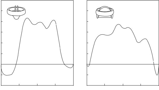
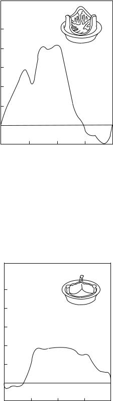
Figure 13 shows the velocity profile distal to a caged ball valve during the peak forward flow phase measured under physiological pulsatile flow in vitro (44). Jet-like flow is observed around the circumference that is separated by the ball and high turbulent stresses were measured at the edge of the jet. A wake is observed behind the ball with slow moving fluid. With the caged ball valve, higher incidences of thrombus deposition have been observed at the top of the cage and correspond to the slow moving fluid in this region behind the wake of the ball. With the tilting disk valves in the fully open position, the blood flows through the major and minor orifices as shown in Fig. 14 where the velocity profile during peak forward flow phase is once again depicted (44). Two jets are formed corresponding to the two orifices with the major orifice jet having larger velocity magnitudes. The amount of blood flow through the major and minor orifices will depend on the angle of opening of the occluder as well as the geometry. A region of reverse flow is also observed adjacent to the valve housing in the minor orifice. The velocity profile measured distal to the leaflet along the major flow orifice in the perpendicular orientation is also included in the figure.
Velocity profiles with three jets corresponding to the central orifice and two peripheral orifices are observed with the bileaflet valve as shown in Fig. 15 (45). The velocity profile along the central orifice in the perpendicular orientation is also included in this figure. Regions of flow reversals near the valve housing are also observed in the figure. Typical magnitudes of turbulent shear stresses measured in the various positions distal to the MHV under pulsatile flow conditions are also included in Table 1. It can be
Axial velocity (cm/s)
150
(a)
100
50
0
−50 |
|
|
|
|
−1.0 |
−0.5 |
0.0 |
0.5 |
1.0 |
Near wall |
|
|
|
Far wall |
|
|
Nondimensional radius |
|
|
Axial velocity (cm/s)
150
(b)
100
50
0
−50 |
|
|
|
|
|
|
|
|
|
|
|
|
|
|
|
|
|
|
|
−1.0 |
−0.5 |
0.0 |
0.5 |
1.0 |
|||||
|
Near wall |
|
|
|
|
|
|
Far wall |
|
|
|
|
|
Nondimensional radius |
|
|
|
|
|
Figure 14. Velocity profile measured distal to a tilting disk valve in the aortic position in vitro in a pulse duplicator using laser Doppler anemometry technique.
Axial velocity (cm/s)
HEART VALVE PROSTHESES |
419 |
125 |
|
|
|
(a) |
125 |
|
|
|
(b) |
100 |
|
|
|
|
100 |
|
|
|
|
75 |
|
|
|
(cm/s) |
75 |
|
|
|
|
25 |
|
|
|
velocityAxial |
25 |
|
|
|
|
50 |
|
|
|
|
50 |
|
|
|
|
0 |
|
|
|
|
0 |
|
|
|
|
−25 |
|
|
|
|
−25 |
|
|
|
|
−50 |
|
|
|
|
−50 |
|
|
|
|
−1.0 |
−0.5 |
0.0 |
0.5 |
1.0 |
−1.0 |
−0.5 |
0.0 |
0.5 |
1.0 |
Near wall |
|
|
|
Far wall |
Near wall |
|
|
|
Far wall |
|
|
Nondimensional radius |
|
|
|
|
Nondimensional radius |
|
|
Figure 15. Velocity profile measured distal to a bileaflet valve in the aortic position in vitro in a pulse duplicator using laser Doppler anemometry technique.
observed that the measured bulk turbulent stresses are large enough to cause hemolysis and platelet activation that can be related to thrombus deposition with MHV. Thrombus deposition is generally observed on the leaflets and the valve housing with the tilting disk valves and also in the hinge region in the case of bileaflet valves.
More recently, it has been suggested that the relatively high turbulent stresses observed during the forward flow phase may not necessarily be the only reason for problems associated with MHV implantation. High turbulent stresses that may damage the formed elements occur in bulk flow distal to and moving away from the valve during the forward flow phase. The activated platelets will need to go through the systemic and pulmonic circulation before it will get deposited once again in the vicinity of the housing in the case of tilting disk and bileaflet valves. Several other experiences with mechanical valve prostheses designs have also indicated the importance of the valve dynamics during the closing phase to be more important for structural integrity and also in the initiation of thrombus. Medtronic Parallel valve design was introduced in the European market in the 1990s with the two leaflets opening to 908 in the fully open position. In vitro studies suggested that the fluid dynamics past this valve in the forward flow phase is superior or at least comparable to the currently available bileaflet valves. However, soon after human implantation trials in Europe, increased incidences of thrombus deposition was observed with this valve model, and hence it was withdrawn from clinical trials.
Another example is a design change in the tilting disk valve resulting in major changes in valve dynamics that
resulted in structural failure in a small percentage of implanted valves. In an effort to increase the flow through the minor orifice with an aim of preventing thrombus deposition, the flat disk geometry of the original Bjork– Shiley valve was changed to a curved geometry in the Bjork–Shiley convexo-concave valve. Even though this design change resulted in improved forward flow hemodynamics, this change resulted in alterations in the dynamics of valve closure with the leaflet overrotating and subjecting the outlet strut to additional loading (46). In a small percentage of valves particularly in the mitral position, single leg separation followed by outlet strut fracture resulted in leaflet escape, and hence this valve was withdrawn from the market. These developments also suggest the importance of understanding the mechanics of valve function throughout the cardiac cycle with any mechanical valve designs. In addition, structural failure and leaflet escape was reported with the implantation of a newly introduced bileaflet valve (Edwards-Duromedics) that resulted in the withdrawal of the valve from the market (47,48). The structural failure was thought to be due to pitting and erosion of the valve structures due to cavitation damage on the pyrolytic carbon (49). These reports also spurred a number of investigations on the closing dynamics and the potential for the mechanical valves to cavitate during the closing phase.
The occluders in the mechanical valves move toward closure with the onset of adverse pressure gradients, and the time taken to move from the fully open to the fully closed position is 30 ms. Toward the end of the leaflet closure, the leaflet edge moves with a velocity of 3–4 m s 1
420 HEART VALVE PROSTHESES
1000.00
(mmHg) |
0.00 |
Pressure |
|
−1000.00
0.00 |
2.00 |
4.00 |
Time (ms)
Figure 16. Typical negative pressure transients recorded at the instant of mechanical heart valve closure (in the mitral position) with the pressure transducer placed very close to the leaflet on the inflow side (atrial side) from in vitro experiments.
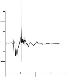
(50–53) and comes to a sudden stop as it impacts the seating lip. This produces a water hammer effect with large positive pressure transient on the outflow side (left ventricle in the mitral position and aorta in the aortic position) and a large negative pressure transient on the inflow side (left atrium in the mitral position and the left ventricular outflow tract in the aortic position). Several in vitro studies have recorded negative pressure transients (54) with magnitudes below that of the vapor pressure for blood (ca. 713 mmHg or 94.8 kPa) and cavitation bubbles have also been visualized at the edge of the leaflets (53–58) in the region corresponding to large negative pressure transients and where the linear velocity of the leaflet edge will be the largest. Figure 16 depicts measured negative pressure transients with the pressure transducer placed near the leaflet edge on the inflow side (atrial side) of the leaflet of a tilting disk valve at the instant of valve closure from in vitro experiments. Note that structural failure due to cavitation type of damage has been reported with only one model of the bileaflet valve and there are no other reports of pitting and erosion on the valve material reported with implanted mechanical valves. It is also not possible to visualize cavitation bubbles in vivo with implanted mechanical valves. However, potential for mechanical valves to cavitate has been demonstrated in an animal model with the recording of negative pressure transients, similar to those measured in vitro, in the left atrium in the vicinity of the implanted mechanical valves in the mitral position (59,60). The actual mechanism of cavitation bubble formation, whether due to the negative pressure magnitudes below the vapor pressure for blood or due to strong vortices forming in the atrial chamber providing additional pressure reductions, is still being debated. It has also been suggested that vortex cavitation
bubbles forming away from the valve surfaces, can trap the dissolved gas from blood and form stable gas bubbles that travel with blood to the circulation and induce neurological deficit due to the gas emboli (61). Number of attempts has also been reported on the detection of the induced cavitation in vivo with implanted mechanical valves from acoustic signals (62–64). Another aspect of MHV cavitation that has been neither fully understood nor fully investigated is the development of stable bubbles, found by microembolic signals (MES) or high intensity transient signals (HITS) during and post-MHV implantation. In vitro studies have shown the development of stable bubbles (HITS) in an artificial heart and closing dynamics experimental models, and are affected by the concentration of CO2(65–67). In vivo, HITS have been visualized during and post-MHV implantation through transcranial Doppler ultrasound (68,69). These events have been implicated as a cause of strokes and neurological deficits. Further evidence has shown that these HITS are in fact, gaseous, and not solid. Patients placed on pure O2 after MHV implantation showed a large decrease in the number of HITS recorded, when compared to patients on normal air (70). These stable bubbles are believed to develop when gaseous nuclei that are present in blood, flow into low pressure regions associated with valve closure. As the valve closes and rebounds inducing vaporous cavitation, gas diffuses into the nuclei enlarging the bubble. When the pressure recovers and the vapor collapses, the bubble dynamics and local fluid mechanics prevent the gas from diffusing back into solution causing the bubble to stabilize and allowing it to flow freely in the vasculature. There is some discussion as to which gas stabilizes the nuclei. Both N2 and CO2 have been suggested as the link to MES/HITS/stable bubble formation (71), but there has yet to be concrete proof indicating which one does.
Large negative pressure transients occur due to the rigidity of the occluder and negative pressures do not occur at the instant of valve closure in the case of bioprosthetic valves (59). In vitro measurements with a tilting disk valve design employing a flexible occluder being implanted in India has also demonstrated that large negative pressures do not develop in such designs because the leaflets deform at the instant of valve closure and absorb part of the energy (12,59).
Irrespective of the formation of cavitation bubbles and subsequent collapse with implanted mechanical valves, the flow induced stresses during the valve closing phase has been suggested as of sufficient magnitude to induce platelet activation and initiation of thrombus. Even if the negative pressure transients do not reach magnitudes below the vapor pressure for blood, the large positive and negative pressure transients on the outflow and inflow sides of the valve at the instant of valve closure can induce high velocity flows through the gap between the leaflet and the housing, in the central gap between the two leaflets in the bileaflet valve, and also through the hinge region. The wall shear stress in the clearance region have been computed to be relatively high, even though present only for a fraction of a second. They induce platelet activation in the region where thrombus deposition is observed with mechanical valves (72). Relatively
high turbulent shear stresses have also been reported from in vitro studies distal to the hinge region of bileaflet valves during the valve closing phase (73,74) indicating the presence of high fluid induced regions near the leaflet edges during the valve closing phase that may be a significant contributor for thrombus initiation.
Most of the studies described above for the measurement of velocity profiles and turbulent stresses employed the laser Doppler velocimetry (LDV) technique. This is a point-velocity measurement technique, and hence measurement of the complete three-dimensional (3D) velocity profile distal to the valve under unsteady flows is tedious and time consuming. On the other hand, particle image velocimetry (PIV) technique has the ability to capture the whole flow field information in a relatively shorter time. Lim et al.employed the PIV technique to study the flow field distal to prosthetic heart valves in steady (75) and pulsatile (76) flow conditions. Along with the description of the flow field at the aortic root that was employed to identify the regions of flow disturbances, they also presented the results of turbulent Reynolds stress and turbulent intensity distributions. Under pulsatile flow conditions distal to a BHV, the velocity vector fields and Reynolds stress mappings at different time steps were used to estimate the damage of shear induced damage to formed elements of blood (76). Browne et al. (77) and Castellini et al. (78) compared the LDV and PIV techniques for the measurement of flow past MHV. Both these works conclude that PIV has the advantage of describing the detailed flow field distal to the valve prostheses in a relatively short time, but LDV technique affords more accurate results in the measurement of turbulent stresses. Regurgitant flow fields and the details of the vortical flow, a potential low pressure field for cavitation initiation have also been measured employing PIV techniques (79,80) and with a combination of PIV and LDV techniques (81).
Bioprosthetic Valve Dynamics
Measurement of velocity profiles and turbulent stresses from in vitro tests in pulse duplicators past BHV have also been reported in the literature (82). Figure 17 depicts typical velocity profiles past a porcine bioprosthesis under normal physiological flow simulation (82). With the porcine valve, a jet-like flow is observed during the peak forward flow phase with high turbulent shear stresses at the edge of the jet. With the pericardial valves (82), the peak velocity magnitudes in the jet-like flow during the peak forward flow phase were smaller than those for the porcine valves in comparable sizes (Fig. 18). It can be observed from Table 1 that the peak turbulent stresses are also smaller in the pericardial valves with geometry closer to the native aortic valves compared to that of the porcine prostheses. It should be noted that the magnitudes of turbulent stresses with the BHV also exceed those values suggested for activation of platelets. However, the leaflets of the BHV are treated biological tissue rather than artificial surfaces. Long-term anticoagulant therapy is generally not required with the implantation of bioprostheses since thrombus initiation is not a significant problem with these valves.
HEART VALVE PROSTHESES |
421 |
|
250 |
|
200 |
(cm/s) |
150 |
Velocity |
100 |
|
50 |
|
0 |
|
−50 |
−1.0 |
−0.5 |
0.0 |
0.5 |
1.0 |
Near wall |
|
|
Far wall |
|
|
Nondimensional radius |
|
||
Figure 17. Velocity profile measured distal to a porcine bioprosthetic valve in the aortic position in vitro in a pulse duplicator using laser Doppler anemometry technique.
On the other hand, these valves fail after an average of 10–12 years of implantation and replacement surgery is required with leaflet failure. A number of studies have been reported on the analysis of the complex leaflet motion during the valve function in order to determine a causative relationship between regions of high stress concentration
|
250 |
|
200 |
(cm/s) |
150 |
Velocity |
100 |
|
|
|
50 |
|
0 |
|
−50 |
−1.0 |
−0.5 |
0.0 |
0.5 |
1.0 |
Near wall |
|
|
Far wall |
|
|
Nondimensional radius |
|
||
Figure 18. Velocity profile measured distal to a pericardial bioprosthetic valve in the aortic position in vitro in a pulse duplicator using laser Doppler anemometry technique.
422 HEART VALVE PROSTHESES
on the leaflets and its attachment sites and structural failure. Based on the analysis of native aortic leaflet motion in vivo with the use of radiopaque markets, it has been reported that the design of the native aortic leaflets affords minimal stresses on the leaflets (33,35). On the other hand, stress analysis on the BHV valve leaflets in vivo suggests that mechanical stresses play a role in calcification of the leaflets (33,34,83). A number of studies has been reported on a finite element stress analysis on the BHV valve leaflets in the closed position in order to correlate regions of high stresses with calcification and tissue failure (84,85). Recent studies have indicated that damage to the valvular structural matrix occurs as the result of mechanical stresses and that the structural damage occurs in spatially distinct sites from those of cuspal mineralization (86). Hence, there is a renewed interest in analyzing the stresses on the leaflets during the opening and closing phases of the leaflet function since loss in flexural rigidity has been demonstrated after the valves undergo 50 million cycles of loading in vitro(87). Detailed analysis on the mechanism of structural failure under cyclic loading requires experimental quantification of the complex motion and also detailed description of the nonlinear anisotropic material property description of the BHV leaflets (88). Leaflet motion quantification by the application of ink markers on the leaflet surface (89), laser profiling technique (90), and noncontacting structured laser light projection technique (91) have been employed for the BHV leaflets. Several studies have been reported on the material characterization of chemically treated BHV leaflet tissue (92–94). Even though these studies have yielded valuable information about the nonlinear material characterization of the leaflets, true physiological characterization requires biaxial loading tests. Recently, constitutive models for the BHV leaflets under biaxial loading have been reported (95,96), which takes into consideration the local architecture of the valve fibers. Since the treated aortic valve leaflet consists of three layers, it can also be anticipated that the behavior of each layer will be different under the physiological loading during the valve opening and closing phases. Recent studies have included separating the fibrosa and ventricularis layers by dissecting microscope and each layer being subjected to biaxial testing (97). Incorporating such detailed material description in the computational analysis in order to determine the flexural and shear stresses on the multilayered tissue leaflets may yield valuable information on the nature of the effect of mechanical stresses on structural disintegration and limited durability with implanted BHV.
Computational Simulation of Heart Valve Function
With the advent of high speed computing capabilities, advances in computational fluid dynamic and finite element numerical analyses algorithms, simulations to determine the mechanical stresses on the blood elements and leaflets during the valve function, is being increasingly employed to understand the mechanics of valve function. In the case of MHV, recent studies have focused on the mechanical stresses developed during the closing phase of valve function. Wall shear stresses of the order of 1000 Pa
have been reported through a numerical simulation in the central clearance of a bileaflet valve with the leaflets in the fully closed position (98). Since the simulation was with the leaflets in the closed position, this simulation did not incorporate the effects of a large pressure gradient across the leaflet at the instant of valve closure (54). A quasistatic simulation in which the leaflets were in the fully closed position and with the application of the measured transient pressures at the instant of valve closure indicated the presence of shear stresses of 2200 Pa (99,100). Employing moving boundaries for the mechanical valve leaflet very near the time of valve closure, simulations of the flow dynamics in the clearance region between the edge of the leaflet and the seat stop have demonstrated fluid velocities of the order of 28 m s 1 with large negative pressure regions on the inflow side of the occluder (101,102). The computed resulting wall shear stress magnitudes at the edge of the leaflet exceeds 17 kPa for a fraction of a second at the instant of valve closure and first rebound after impact with the seat stop (72).
In the case of BHV, finite element analysis has been the popular technique employed to determine the stress distribution on the leaflets with the blood pressure applied as the load on the leaflets. Such analyses have also been employed to perform stress analysis with native aortic and mitral valves (103,104). Stress analysis with BHV geometry have incorporated the nonlinear material property of the leaflets and employed both the rigid and flexible stent support (84,85). These results have generally suggested a correlation between regions of high stresses with the leaflets in the fully closed position and calcification observed with implanted valves.
Numerical simulation of native and prosthetic heart valve function is quite challenging with the necessity of addressing several difficult issues. In the case of MHV simulation, the mesh generation for the detailed 3D geometry of the tilting disk and bileaflet valves, including the complex geometry of the hinge mechanism, is required. The simulation must also have the ability to deal with the moving leaflets. In the case of BHV simulation, it is necessary to incorporate the nonlinear anisotropic material property of the leaflets and compute the complex motion of the leaflets due to the external load imparted on the same by the surrounding fluid. In modeling the valve function, the fluid domain is most conveniently described using the Eulerian reference frame in which the fluid moves through a fixed mesh. A Lagrangian formulation is more appropriate for the leaflet motion in which the mesh moves together with the leaflet. The complete simulation of the heart valve function requires a fluid-structure interaction simulation and the two formulations are incompatible for such an analysis. Two methods have generally been employed to circumvent this problem. An Eulerian method used in the simulation of heart valve function is the fictitious domain method employed by de Hart et al. (105,106) and Baaijens (107). This simulation requires careful attention to accurate mesh representation for flows near the leaflet due to the use of fixed grid and numerical stability. It is also computationally very intensive. The second approach is the arbitrary Lagrangian–Eulerian (ALE) method in which the computational mesh is allowed
to deform (108) and move in space arbitrarily to conform to the moving boundaries. It has also been successfully employed in the heart valve simulation. The disadvantage with this method is the need for a mechanism to adapt or deform the mesh to conform to the boundary motion at each new time step. Large and complex deformation of the BHV leaflets within the computational domain makes the mesh adaptation very difficult when structured mesh is used and the mesh topology has to be maintained. Mesh regeneration has been employed to avoid the problems with the maintenance of mesh topology, and requires reinterpolation of the flow variables that can be expensive to perform and may result in large artificial errors. The ALE method recently has been employed in the simulation of prosthetic valve function by several investigators (102,109–111). More recently, a fluid-structure interaction simulation for the mechanical valve closing dynamics employing the ALE method has been presented for both two-dimensional (2D) (112) and 3D (72) geometry of a bileaflet valve. In this analysis in which the details of the hinge geometry was not included, the leaflet was specified to rotate around an axis and the motion of the leaflets was computed by solving the governing equation of motion for the leaflet with fluidinduced stresses specified as the external load. The pressure and velocity field is calculated employing the CFD solver employing the ALE method. The grid points on the leaflets are rotated, based on the solution of the equation of motion of the leaflet. An elliptic solver is employed to the entire mesh using the initial methods and the computed displacement of the leaflet grid points. This simulation has also clearly demonstrated the presence of abnormally high wall shear stresses in the clearance region of the leaflet and the valve housing at the instant of valve closure and leaflet rebound. These studies indicate that the shear stresstime magnitude present in this region far exceeds magnitudes suggested for platelet activation, and hence may be the critical factor for thrombus initiation with MHV implants.
SUMMARY
Since the introduction of the first prosthetic valve replacement for a diseased native heart valve > 40 years ago, numerous developments in design and manufacturing process have resulted in improved performance of these implants and patients are leading a relatively normal life. Continued efforts are underway to minimize the effect of thrombus deposition with MHV and to improve the durability of implanted BHV. State-of-the-art experimental techniques and computational simulations are being applied to improve our understanding on the relationship between the complex solid and fluid mechanics during the prosthetic valve function and its relationship with the problems still continuing to be observed with the implants. With the advent of high performance computers and advances in computational flow dynamics algorithms, more detailed 3D unsteady laminar and disturbed flow simulations are becoming a reality today. Development of fluid–structure interaction simulations, inclusion of detailed structural analysis of biological leaflet valves during the valve function, and the behavior of platelets
HEART VALVE PROSTHESES |
423 |
and red blood cells in the unsteady 3D flow field to simulate the platelet and red blood cell motion in the crevices are crucial for our further understanding of the mechanical valve function. However, complementary experimental studies to validate the simulations are also essential to gain confidence in the results of the complicated numerical simulations. A deterministic study of the effect of such stresses on the leaflet structures as well as formed elements in blood will require an analysis that includes computational algorithms that span multiple length and time scales. Efforts are underway to develop such simulations. These studies will also provide valuable information toward the development of tissue engineered valve replacements.
BIBLIOGRAPHY
Cited References
1.Yoganathan A, Lemmon JD, Ellis JT. Heart Valve Dynamics. In: Bronzino JD, editor. The Biomedical Engineering Handbook. 2nd ed. Boca Raton: CRC Press and IEEE Press; 2000. p 29.1–29.15.
2.Westaby S, Karp RB, Blackstone EH, Bishop SP. Adult human valve dimensions and their surgical significance. Am J Cardiol 1984;53(4):552–556.
3.Davies MJ. Pathology of Cardiac Valves. London: Butterworth; 1980.
4.Gorlin R, Gorlin SG. Hydraulic formula for calculation of the area of the stenotic mitral valve, other cardiac valves, and central circulatory shunts. I Am Heart J 1951;41(1):1–29.
5.Schlant RC, Alexander RW, editors. Technique of Doppler and color flow Doppler in the evaluation of cardiac disorders and function. in The Heart: Arteries and Veins. The Heart: Arteries and Veins. 6th ed. New York: McGraw-Hill; 1994.
6.Braunwald E. Heart Disease: A Textbook of Cardiovascular Medicine. 2nd ed. Philadelphia: W. B. Saunders; 1984.
7.Aazami M, Schafers HJ. Advances in heart valve surgery. J Interv Cardiol 2003;16(6):535–541.
8.Harken DE, Taylor WJ, Lefemine AA, Lunzer S, Low HB, Cohen ML, Jacobey JA. Aortic valve replacement with a caged ball valve. Am J Cardiol 1962;9:292–299.
9.Hammermeister K, Sethi GK, Henderson WG, Grover FL, Oprian C, Rahimtoola SH. Outcomes 15 years after valve replacement with a mechanical versus a bioprosthetic valve: final report of the Veterans Affairs randomized trial. J Am Coll Cardiol 2000;36(4):1152–1158.
10.Bach DS. Choice of prosthetic heart valves: update for the next generation. J Am Coll Cardiol 2003;42(10):1717–1719.
11.Starr A, Edwards ML. Mitral replacement: Clinical experience with a ball valve prosthesis. Ann Surg 1961;154:726.
12.Bhuvaneshwar G, Ramani AV, Chandran KB. Polymeric occluders in tilting disk heart valve prostheses. In: Dumitriu S, editor. Polymeric Biomaterials. 2nd ed. New York: Marcel Dekker; 2002. p 589–610.
13.Chandran KB. Dynamic behavior analysis of mechanical heart valve prostheses. In: Leondes C, editor. Cardiovascular Techniques. Boca Raton: CRC Press; 2001. p 3.1–3.31.
14.Yoganathan A. Cardiac valve prostheses. In: Bronzino JD, editor. Biomedical Engineering Handbook. Boca Raton: CRC Press and IEEE Press; 2000. p 127.1–127.23.
15.Wada J. Knotless suture method and Wada hingeless valve. Jpn J Thor Sur 1967;15:88.
16.Bjork VO. Experience with the Wada-Cutter valve prostheses in the aortic areaOne year follow-up. J Thorac Cardiovasc Surg 1970;60:26.
424HEART VALVE PROSTHESES
17.Bjork VO. A new tilting disk valve prostheses. Scand J Cardiovasc Surg 1969;3:1.
18.Bjork VO. Delrin as implant material for valve occluders. Scand J Thorac Cardiovasc Surg 1972;6:103.
19.Bjork VO. The pyrolytic carbon occluder for the Bjork–Shiley tilting disk valve prostheses. Scand J Thorac Cardiovasc Surg 1972;6:109–113.
20.Butchart EG, Bodnar E. Thrombosis, Embolism, and Bleeding. Marlow, Bucks (UK): ICR Publishing; 1992.
21.Carpentier A, Lamaigre RL, Carpentier S, Dubost C. Biological factors affecting long-term results of valvular heterografts. J Thorac Cardiovasc Surg 1969;58:467.
22.O’Brien M, Clarebrough JK. Heterograft aortic valve transplant for human valve disease. Aust Med J 1966;2(228).
23.Carpentier A, Dubost C. From xenograft to bioprosthesis: Evolution of concepts and techniques of valvular xenografts. In: Ionescu MI, Ross DN, Wooler GH, editors. Biological Tissue in Heart Valve Replacement. London: Butterworth; 1971. p 515–541.
24.Yoganathan AP. Cardiac Valve Prostheses. In: Bronzino JD, editor. The Biomedical Engineering Handbook. 2nd ed. Boca Raton (FL): CRC Press; 2000. p 127.1–127.23.
25.Wieting DW. Dynamic flow characteristics of heart valves, Ph.D., dissertation. University of Texas, Austin, TX.
26.Cape EG, Nanda NC, Yoganathan AP. Quantification of regurgitant flow through bileaflet heart valve prostheses: theoretical and in vitro studies. Ultrasound Med Biol 1993;19(6):461–468.
27.Cape EG, Kim YH, Heinrich RS, Grimes RY, Muralidharan E, Broder JD, Schwammenthal E, Yoganathan AP, Levine RA. Cardiac motion can alter proximal isovelocity surface area calculations of regurgitant flow. J Am Coll Cardiol 1993;22(6):1730–1737.
28.Edmunds LH Jr. Thrombotic and bleeding complications of prosthetic heart valves. Ann Thorac Surg 1987;44(4):430–445.
29.Paulsen PK, Nygaard H, Hasenkam JM, Gormsen J, Stodkilde-Jorgensen H, Albrechtsen O. Analysis of velocity in the ascending aorta in humans. A comparative study among normal aortic valves, St. Jude Medical and StarrEdwards Silastic Ball valves. Int J Artif Organs 1988;11(4): 293–302.
30.Farthing S, Peronneau P. Flow in the thoracic aorta. Cardiovasc Res 1979;13(11):607–620.
31.Rossvoll O, Samstad S, Torp HG, Linker DT, Skjaerpe T, Angelsen BA, Hatle L. The velocity distribution in the aortic anulus in normal subjects: a quantitative analysis of twodimensional Doppler flow maps. J Am Soc Echocardiogr 1991;4(4):367–378.
32.Kilner PJ, Yang GZ, Mohiaddin RH, Firmin DN, Longmore DB. Helical and retrograde secondary flow patterns in the aortic arch studied by three-directional magnetic resonance velocity mapping. Circulation 1993;88(5 Pt 1):2235–2247.
33.Thubrikar M, Piepgrass WC, Shaner TW, Nolan SP. The design of the normal aortic valve. Am J Physiol 1981; 241(6):H795–801.
34.Thubrikar MJ, Skinner JR, Eppink RT, Nolan SP. Stress analysis of porcine bioprosthetic heart valves in vivo. J Biomed Mater Res 1982;16(6):811–826.
35.Thubrikar M, Skinner JR, Aouad J, Finkelmeier BA, Nolan SP. Analysis of the design and dynamics of aortic bioprostheses in vivo. J Thorac Cardiovasc Surg 1982;84(2):282–290.
36.Thubrikar M, Eppink RT. A method for analysis of bending and shearing deformations in biological tissue. J Biomech 1982;15(7):529–535.
37.Thubrikar M, Carabello BA, Aouad J, Nolan SP. Interpretation of aortic root angiography in dogs and in humans. Cardiovasc Res 1982;16(1):16–21.
38.Nevaril C, Hellums J, Alfrey C Jr. Physical effects in red blood cell trauma. J Am Inst Chem Eng 1969;15:707.
39.Mohandas N, Hochmuth RM, Spaeth EE. Adhesion of red cells to foreign surfaces in the presence of flow. J Biomed Mater Res 1974;8(2):119–136.
40.Sutera SP, Mehrjardi MH. Deformation and fragmentation of human red blood cells in turbulent shear flow. Biophys J 1975;15(1):1–10.
41.Ramstack JM, Zuckerman L, Mockros LF. Shear-induced activation of platelets. J Biomech 1979;12(2):113–125.
42.Anderson GH, Hellums JD, Moake JL, Alfrey CP Jr. Platelet lysis and aggregation in shear fields. Blood Cells 1978;4(3): 499–511.
43.Yoganathan AP, Corcoran WH, Harrison EC. In vitro velocity measurements in the vicinity of aortic prostheses. J Biomech 1979;12(2):135–152.
44.Chandran KB, Cabell GN, Khalighi B, Chen CJ. Laser anemometry measurements of pulsatile flow past aortic valve prostheses. J Biomech 1983;16(10):865–873.
45.Chandran KB. Pulsatile flow past St. Jude Medical bileaflet valve. An in vitro study. J Thorac Cardiovasc Surg 1985; 89(5):743–749.
46.Chandran KB, Lee CS, Aluri S, Dellsperger KC, Schreck S, Wieting DW. Pressure distribution near the occluders and impact forces on the outlet struts of Bjork–Shiley convexoconcave valves during closing. J Heart Valve Dis 1996; 5(2):199–206.
47.Dimitri W, Williams BT. Fracture of a Duromedics mitral valve housing with leaflet escape. J Cardiovas Sur 1990; 31:41–46.
48.Deuvaert FE, Devriendt J, Massaut J. Leaflet escape of a mitral Duromedics prosthesis (case report). Acta Chirur 1989;89:15–18.
49.Kafesjian R, Howanec M, Ward GD, Diep L, Wagstaff LS, Rhee R. Cavitation damage of pyrolytic carbon in mechanical heart valves. J Heart Valve Dis 1994;3:S2–S7.
50.Guo GX, Chiang TH, Quijano RC, Hwang NH. The closing velocity of mechanical heart valve leaflets. Med Eng Phys 1994;16(6):458–464.
51.Wu ZJ, Shu MC, Scott DR, Hwang NH. The closing behavior of Medtronic Hall mechanical heart valves. ASAIO J 1994;40(3):M702–6.
52.Wu ZJ, Wang Y, Hwang NH. Occluder closing behavior: a key factor in mechanical heart valve cavitation. J Heart Valve Dis 1994;3(Suppl 1):S25–33; discussion S33–4.
53.Chandran KB, Aluri S. Mechanical valve closing dynamics: relationship between velocity of closing, pressure transients, and cavitation initiation. Ann Biomed Eng 1997;25 (6):926– 938.
54.Chandran KB, Lee CS, Chen LD. Pressure field in the vicinity of mechanical valve occluders at the instant of valve closure: correlation with cavitation initiation. J Heart Valve Dis 1994;3(Suppl 1):S65–75; discussion S75–6.
55.Graf T, Reul H, Dietz W, Wilmes R, Rau G. Cavitation of mechanical heart valves under physiologic conditions. J Heart Valve Dis 1992;1(1):131–141.
56.Graf T, Fischer H, Reul H, Rau G. Cavitation potential of mechanical heart valve prostheses. Int J Artif Organs 1991;14(3):169–174.
57.Zapanta CM, Liszka EG Jr., Lamson TC, Stinebring DR, Deutsch S, Geselowitz DB, Tarbell JM. A method for realtime in vitro observation of cavitation on prosthetic heart valves. J Biomech Eng 1994;116(4):460–468.
58.Garrison LA, Lamson TC, Deutsch S, Geselowitz DB, Gaumond RP, Tarbell JM. An in vitro investigation of prosthetic heart valve cavitation in blood. J Heart Valve Dis 1994; 3(Suppl 1):S8–22; discussion S22–4.
59.Chandran KB, Dexter EU, Aluri S, Richenbacher WE. Negative pressure transients with mechanical heart-valve closure: correlation between in vitro and in vivo results. Ann Biomed Eng 1998;26(4):546–556.
60.Dexter EU, Aluri S, Radcliffe RR, Zhu H, Carlson DD, Heilman TE, Chandran KB, Richenbacher WE. In vivo demonstration of cavitation potential of a mechanical heart valve. ASAIO J 1999;45(5):436–441.
61.Kleine P, Perthel M, Hasenkam JM, Nygaard H, Hansen SB, Laas J. High-intensity transient signals (HITS) as a parameter for optimum orientation of mechanical aortic valves. Thorac Cardiovasc Surg 2000;48(6):360–363.
62.Johansen P, Andersen TS, Hasenkam JM, Nygaard H. In-vivo prediction of cavitation near a Medtronic Hall valve. J Heart Valve Dis 2004;13(4):651–658.
63.Johansen P, Manning KB, Tarbell JM, Fontaine AA, Deutsch S, Nygaard H. A new method for evaluation of cavitation near mechanical heart valves. J Biomech Eng 2003;125(5):663–670.
64.Johansen P, Travis BR, Paulsen PK, Nygaard H, Hasenkam JM. Cavitation caused by mechanical heart valve pros- theses—a review. APMIS 2003;(Suppl)(109):108–112.
65.Biancucci BA, Deutsch S, Geselowitz DB, Tarbell JM. In vitro studies of gas bubble formation by mechanical heart valves. J Heart Valve Dis 1999;8(2):186–196.
66.Lin HY, Bianccucci BA, Deutsch S, Fontaine AA, Tarbell JM. Observation and quantification of gas bubble formation on a mechanical heart valve. J Biomech Eng 2000;122 (4):304–309.
67.Bachmann C, Kini V, Deutsch S, Fontaine AA, Tarbell JM. Mechanisms of cavitation and the formation of stable bubbles
on the Bjork–Shiley Monostrut prosthetic heart valve. J Heart Valve Dis 2002;11(1):105–113.
68.Dauzat M, Deklunder G, Aldis A, Rabinovitch M, Burte F, Bret PM. Gas bubble emboli detected by transcranial Doppler sonography in patients with prosthetic heart valves: a preliminary report. J Ultrasound Med 1994;13(2):129–35.
69.Reisner SA, Rinkevich D, Markiewicz W, Adler Z, Milo S. Spontaneous echocardiographic contrast with the carbomedics mitral valve prosthesis. Am J Cardiol 1992;70(18): 1497–1500.
70.Droste DW, Hansberg T, Kemeny V, Hammel D, SchulteAltedorneburg G, Nabavi DG, Kaps M, Scheld HH, Ringelstein EB. Oxygen inhalation can differentiate gaseous from nongaseous microemboli detected by transcranial Doppler ultrasound. Stroke 1997;28(12):2453–2456.
71.Georgiadis D, Wenzel A, Lehmann D, Lindner A, Zerkowski HR, Zierz S, Spencer MP. Influence of oxygen ventilation on Doppler microemboli signals in patients with artificial heart valves. Stroke 1997;28(11):2189–2194.
72.Cheng R, Lai YG, Chandran KB. Three-dimensional fluidstructure interaction simulation of bileaflet mechanical heart valve flow dynamics. Ann Biomed Eng 2004;32(11): 1469–1481.
73.Ellis JT, Yoganathan AP. A comparison of the hinge and near-hinge flow fields of the St Jude medical hemodynamic plus and regent bileaflet mechanical heart valves. J Thorac Cardiovasc Surg 2000;119(1):83–93.
74.Saxena R, Lemmon J, Ellis J, Yoganathan A. An in vitro assessment by means of laser Doppler velocimetry of the Medtronic advantage bileaflet mechanical heart valve hinge flow. J Thorac Cardiovasc Surg 2003;126(1):90–98.
75.Lim WL, Chew YT, Chew TC, Low HT. Steady flow dynamics of prosthetic aortic heart valves: a comparative evaluation with PIV techniques. J Biomech 1998;31(5):411–421.
76.Lim WL, Chew YT, Chew TC, Low HT. Pulsatile flow studies of a porcine bioprosthetic aortic valve in vitro: PIV measurements and shear-induced blood damage. J Biomech 2001; 34(11):1417–1427.
77.Browne P, Ramuzat A, Saxena R, Yoganathan AP. Experimental investigation of the steady flow downstream of the St.
HEART VALVE PROSTHESES |
425 |
Jude bileaflet heart valve: a comparison between laser Doppler velocimetry and particle image velocimetry techniques. Ann Biomed Eng 2000;28(1):39–47.
78.Castellini P, Pinotti M, Scalise L. Particle image velocimetry for flow analysis in longitudinal planes across a mechanical artificial heart valve. Artif Organs 2004;28(5):507–513.
79.Manning KB, Kini V, Fontaine AA, Deutsch S, Tarbell JM. Regurgitant flow field characteristics of the St. Jude bileaflet mechanical heart valve under physiologic pulsatile flow using particle image velocimetry. Artif Organs 2003;27(9):840–846.
80.Kini V, Bachmann C, Fontaine A, Deutsch S, Tarbell JM. Flow visualization in mechanical heart valves: occluder rebound and cavitation potential. Ann Biomed Eng 2000; 28(4):431–441.
81.Kini V, Bachmann C, Fontaine A, Deutsch S, Tarbell JM. Integrating particle image velocimetry and laser Doppler velocimetry measurements of the regurgitant flow field past mechanical heart valves. Artif Organs 2001;25(2):136–145.
82.Chandran KB, Cabell GN, Khalighi B, Chen CJ. Pulsatile flow past aortic valve bioprostheses in a model human aorta. J Biomech 1984;17(8):609–619.
83.Thubrikar MJ, Deck JD, Aouad J, Nolan SP. Role of mechanical stress in calcification of aortic bioprosthetic valves. J Thorac Cardiovasc Surg 1983;86(1):115–125.
84.Hamid MS, Sabbah HN, Stein PD. Influence of stent height upon stresses on the cusps of closed bioprosthetic valves. J Biomech 1986;19(9):759–769.
85.Rousseau EP, van Steenhoven AA, Janssen JD. A mechanical
analysis of the closed Hancock heart valve prosthesis. J Biomech 1988;21(7):545–562.
86.Sacks MS, Schoen FJ. Collagen fiber disruption occurs independent of calcification in clinically explanted bioprosthetic heart valves. J Biomed Mat Res 2002;62(3):359–371.
87.Gloeckner DC, Billiar KL, Sacks MS. Effects of mechanical fatigue on the bending properties of the porcine bioprosthetic heart valve. ASAIO J 1999;45(1):59–63.
88.Sacks MS. The biomechanical effects of fatigue on the porcine bioprosthetic heart valve. J Long-Term Effects Med Implants 2001;11(3–4):231–247.
89.Lo D, Vesely I. Biaxial strain analysis of the porcine aortic valve. Ann Thorac Surg 1995;60(2 Suppl):S374–8.
90.Donn AW, Bernacca GM, Mackay TG, Gulbransen MJ, Wheatley DJ. Laser profiling of bovine pericardial heart valves. Int J Artif Organs 1997;20(8):436–439.
91.Iyengar AKS, Sugimoto H, Smith DB, Sacks MS. Dynamic in vitro quantification of bioprosthetic heart valve leaflet motion using structured light projection. Ann Biomed Eng 2001;29(11):963–973.
92.Lee JM, Boughner DR, Courtman DW. The gluteraldehydestabilized porcine aortic valve xenograft. II. Effect of fixation with or without pressure on the tensile viscoelastic properties of the leaflet material. J Biomed Mater Res 1984;18 (1):79–98.
93.Lee JM, Courtman DW, Boughner DR. The gluteraldehydestabilized porcine aortic valve xenograft. I. Tensile viscoelastic properties of the fresh leaflet material. J Biomed Mater Res 1984;18(1):61–77.
94.Vesely I, Noseworthy R. Micromechanics of the fibrosa and the ventricularis in aortic valve leaflets. J Biomech 1992;25(1): 101– 113.
95.Billiar KL, Sacks MS. Biaxial mechanical properties of the native and gluteraldehyde-treated aortic valve cusp: Part II—A structural constitutive model. J Biomech Eng 2000;122(4):327–335.
96.Billiar KL, Sacks MS. Biaxial mechanical properties of the natural and gluteraldehyde treated aortic valve cusp—Part I: Experimental results. J Biomech Eng 2000;122(1):23–30.
97.Sacks M, Stella J, Chandran KB. A bi-layer structural constitutive model for the aortic valve leaflet. Philadelphia: BMES Annu Conf, Abstract No. 1164, 2004.