

20.Zwarts MJ, Stegeman DF. Muscle Nerve 2003;28(1):1–17.
21.Light CM, Chappell PH, Hudgins B, Engelhart K. Med Eng Technol 2002;26(4):139–146.
22.Nawab SH, Roy SH, De Luca CJ. The 26th Int Conf IEEE Eng Med Biol Soc; San Francisco; 2004. p 979–982.
23.Roy SH, Cheng MS, De Luca CJ. Boston: ISEK Congress; 2004.
24.Nawab SH, Wotiz R, Hochstein L, De Luca CJ. Proceedings of the Second Joint Meeting of the IEEE Eng Med and Biol Soc and the Biomed Eng Soc; Houston: 2002. p 36–36.
25.Basmajian JV, De Luca CJ. Muscles Alive. 5th ed. Baltimore: Williams & Wilkins; 1985.
26.De Luca CJ. Muscle Nerve 1993;16:210–216.
27.LeFever RS, De Luca CJ. Proc Annu Conf Eng Med Biol 1976;18:56.
28.Lago P, Jones NB. Med Biol Eng Comput 1977;15:648.
29.Buchthal F, Guld C, Rosenfalck P. Acta Physiol Scand 1957;39:83.
30.De Luca CJ, Forrest WJ. IEEE Trans Biomed Eng BME 1972;19:367.
31.Basmajian JV, Stecko GA. J Appl Physiol 1962;17:849.
32.Willison RG. J Physiol (London) 1963;168:35.
33.Lindstrom LR, Broman H, Magnusson R, Petersen I. Neurophysiology 1973;7:801.
34.Stulen FB, De Luca CJ. IEEE Trans Biomed Eng BME 1981;28:515.
35.Constable R, Thornhill RJ, Carpenter RR. Biomed Sci Instrum 1994;30:69.
See also ELECTROPHYSIOLOGY; REHABILITATION AND MUSCLE TESTING.
ELECTRON MICROSCOPY. See MICROSCOPY,
ELECTRON.
ELECTRONEUROGRAPHY
THOMAS SINKJÆR
KEN YOSHIDA
WINNIE JENSEN
VEIT SCHNABEL
Aalborg University
Aalborg, Denmark
INTRODUCTION
Recording techniques developed over the past three decades have made it possible to study the peripheral and central nervous system (CNS) in detail and often during unconstrained conditions. There have been many studies using the ElectroNeuroGram (ENG) to investigate the physiology of the neuromuscular system, in particular, chronic studies in freely moving animals (1,2). Other studies relate to monitoring the state of the nerve (e.g., in relation to axotomized nerves and regeneration of nerve fibers). Clinically, the ENG is used to measure the conduction velocities and latencies in peripheral nerves by stimulating a nerve at different points along the nerve. Extracellular potentials can be recorded by either con-
ELECTRONEUROGRAPHY 109
centric needle electrodes or surface electrodes. The potentials can be derived from purely sensory nerve, from sensory components of mixed nerve, or from motor nerves
(3). The study of extracellular potentials from sensory nerves in general has been shown to be of considerable value in diagnosing peripheral nerve disorders. For an indebt description of the ENG in clinical neurophysiology see Ref. 4. Several studies pertain to the use of sensory signals as feedback information to control neuroprosthetic devices. Studies (5) have shown that the application of closed-loop control techniques can improve the regulation of the muscle activation. Techniques using an electrical interface to nerves innervating natural sensors (6–12), such as those found in the skin, muscles, tendons, and joints are an attractive alternative to artificial sensors. Since these natural sensors are present throughout the body, remain functional after injury, and are optimally placed through evolution to provide information for natural feedback control, a rich source of information that could be used to control future FES devices exists as long as a method can be found to access them.
Interestingly, much of the peripheral sensory apparatus in spinal and brain-injured human individuals is viable. This means that the natural sensors are transmitting relevant nerve signals through the peripheral nervous system. Therefore, if the body’s natural sensors are to provide a suitable feedback signal for the control of FES systems in paralyzed subjects, the challenge is to be able to extract reliable and relevant information from the nerve innervating the sensors over extended periods.
The nerve cuff electrode still has an unrivaled position as a tool for recording ENG signals from peripheral nerves in chronic experiments (13,14) and as means to provide information to be used in neural prosthesis systems (9,15,16). Other kinds of electrodes are to challenge the cuff electrode, such as intra-fascicular electrodes (6,10,18) or multisite electrodes with hundreds of contacts within a few cubic millimeters (2,10,11,17–19). These types of nerve-interface provide advantages with respect to selectivity and number of sensors.
This article describes the characteristics of the peripheral nerve signals, principals of neural recordings, and the signals obtained with different electrodes in long-term implants. An essential part in the success of recording peripheral neural signals or activating peripheral neural tissue is the neural interface.
THE PERIPHERAL NERVOUS SYSTEM
A peripheral nerve contains thousands of nerve fibers, each of them transmitting information, either from the periphery to the CNS or from the CNS to the periphery. The efferent fibers transmit information to actuators; mainly muscles, whereas afferent fibers transmit sensory information about the state of organs and events (e.g., muscle length, touch, skin temperature, joint angles, nociception, and several other modalities of sensory information). Most of the peripheral nerves contain both afferent and efferent fibers, and the peripheral nerve can thus be seen as a bidirectional information channel.
110 ELECTRONEUROGRAPHY
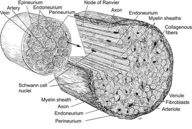
Figure 1. Figure showing the structure and components of the peripheral nerve trunk. (Adapted from Crouche, 1969, with permission.)
Anatomical Definitions and Structures
If the CNS is defined as the tissues and neural circuitry that comprise the brain and spinal cord, the peripheral nervous system can be defined as the part of the nervous system that lies outside of the CNS. Given some generalization of this definition, the peripheral nervous system consists of the spinal roots, dorsal root ganglions, axons/dendrites, support cells, and sensory end organs. The structure of the peripheral nerve trunk is illustrated below showing the following: nerve trunk, nerve fascicle, axon, schwann cells, epineurium, perineurium, and endoneurium. Though not generally considered part of the peripheral nerve, the nerve can also contain resident macrophages, leucocytes, and other cell types involved in the inflammatory response (Fig. 1).
THE NEURO-ELECTRONIC INTERFACE
The ENG can be described as the extracellular potential of an active peripheral nerve recorded at some distance from the nerve or from within the nerve trunk. The extracellular potential is formed from the contributions of the superimposed electrical fields of the active sources within the nerve. The general form of the extracellular response of a whole nerve to electrical stimulation is triphasic, it is in the lower end of the microvolt scale in amplitude, and looses both amplitude and high frequency content at larger radial distances from the nerve trunk (20).
Principles of Nerve Recordings
All cells of the body have a membrane potential. The membrane potential is a consequence of the cell membrane being selectively permeable to different ion species, resulting in different ion concentrations at the intracellular and extracellular space. The difference in ion concentrations causes an electrochemical voltage difference across the membrane, called the membrane potential. Under normal physiological conditions, the interior of the cell is negative with respect to the extracellular space without a net electric current flowing through the membrane. Therefore, if a
macroscopic view of the cell membrane is justified (i.e., at distances that are large with respect to the thickness of the membrane), the existence of the resting membrane potential cannot be detected at the extracellular space.
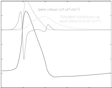
Action Potentials. The change in membrane permeability is achieved by opening and closing of ion channels. The kinetics of the opening and closing of the channels determines the shape of the membrane current, which is characteristic for different types of nerve and muscle cells. The membrane potential changes as current flows through the membrane. The course of the membrane potential, from its resting state over an entire cycle of opening and closing of ion channels back to the initial state, is called the action potential. The associated current flowing through the membrane is the action current (Fig. 2).
A widely used model of peripheral myelinated nerve fibers is based on the model of single action potentials of fibers from rabbit sciatic nerve by Chiu et al. (22), comprising only sodium current and a leakage current. This model was adapted to 37 8C and to human peripheral nerve conduction velocity by Sweeney et al. (23).
An extensive review of different membrane models can be found in Varghese (24). More recent modeling work of human fibers includes Wesselink et al. (25) and McIntyre et al. (25).
Extracellular Currents and Potential Distribution. During the action potential, current is entering and leaving the cell through the membrane. Since there are no sources or sinks of electricity in the nerve fibers, the current flows in closed loops, and the current entering the cell at one site has to leave at a remote location. Likewise, the current leaving the cell has to reenter at a distant location, resulting in the redistribution and conduction of the current through the extracellular space. The extracellular conduction current (or, more precisely, its associated electric or magnetic field) can be detected and measured. The electroneurogram measures the electric potential field generated by the ensemble of extracellular conduction currents originating from active sites at many different fibers.
Vm, mV |
|
|
|
|
Im, A/m2 |
50 |
|
|
|
|
2 |
|
Action |
Sodium conductance gNa |
|
|
|
|
|
|
|
|
|
|
current |
|
|
|
|
25 |
Im |
|
|
|
1 |
0 |
|
|
|
|
0 |
-25 |
|
|
|
|
-1 |
|
Action |
|
|
|
|
|
potential |
|
|
|
|
-50 |
Vm |
|
|
|
-2 |
-75 |
|
|
|
|
-3 |
-100 |
2 |
4 |
6 |
8 |
-4 |
0 |
10 |
||||
|
|
Time t, ms |
|
|
|
ELECTRONEUROGRAPHY 111
Figure 2. Action potential and action current of the squid giant axon (unmyelinated nerve fiber). Time course of the propagating action potential Vm and action current Im according to the Hodgkin and Huxley model (21). After initial depolarization, the sodium channels open, resulting in a 100-fold increase of sodium conductance, and thus inflow of sodium ions, which depolarizes the membrane potential even further. The delayed opening of the potassium channels (potassium outflow) and closing of sodium channels repolarizes the membrane potential, with a phase of hyperpolarization (below resting potential).
For the case of a single active myelinated fiber in an unbound homogeneous medium, the fiber can simply be modeled as a series of point current sources, representing the nodes of Ranvier, where current is entering and leaving the fiber (if myelin is assumed to be a perfect insulator). The extracellular potential w of an active fiber can then easily be calculated by superposition of the electric potential fields of point current sources as follows (26):
’ x; y; t |
|
1 |
|
Imðt xn=vÞ |
|
||||||
ð |
Þ ¼ 4ps n |
q |
|||||||||
|
2 |
þ ð |
|
|
|
Þ |
2 |
||||
|
|
|
X |
y |
|
x |
xn |
|
|||
|
|
|
|
|
|
|
|
||||
where s is the conductivity, Im the action current (Fig. 2), v the propagation velocity, and (xn, 0) the position of the node of Ranvier n.
Figure 2 shows the extracellular potential w(0, y,t) of a single active myelinated fiber (10 mm) in unbound homogeneous medium for different distances y from the fiber. For very short distances from the fiber (y ¼ 1 mm, corresponding to one internodal distance), the extracellular potential follows mostly the shape of the action current from the closest node of Ranvier. With increasing distance from the fiber, not only does the amplitude of the extracellular potential drop rapidly down, but also its shape changes as the potential is averaged over increasingly numbers of active nodes. The influence of fiber diameter and distance from the fiber on the amplitude and duration of the extracellular potential has been discussed in detail in Struijk (26).
The amplitude and shape of the extracellular potential are also strongly influenced by inhomogeneities in the surrounding medium, called the volume conductor (e.g., the highly resistive perineurium, surrounding tissue, or cuff electrodes). For a more realistic (complex) volume conductor than the above infinitely large, homogeneous case, numerical methods are required to calculate the distribution of the
extracellular potential, such as harmonic series expansion, finite difference, or finite element methods.
Electrodes measure the extracellular potential by physically sampling the electric potential in the extracellular space. Depending on the electrode type, this yields either point-wise information (intrafascicular electrodes, needle electrodes, electrode arrays) or measurements averaged over a larger volume (cuff electrodes, surface electrodes). The configuration (monopolar, bipolar, tripolar) and spacing of the electrodes further affect the recording characteristics (e.g., noise rejection, spatial selectivity, diameter selectivity). Computer models are helpful in understanding these recording characteristics and for the development of electrodes with improved selectivity (27–29).
Neural Signals
Neural Signal Characteristics. The previous section, gives the theoretical basis of how the action potential is generated, and how this, in turn, results in a change in the electric field in the extracellular space. These potentials can be detected using electrodes in various recording configurations to maximize the neural signal detected and minimize the noise pickup. These configurations will be discussed in the next section. Here, the ENG signal is characterized. A starting point is to take recordings made by electrodes placed within the nerve fascicle, such as a longitudinal intra–fascicular electrode (LIFE).
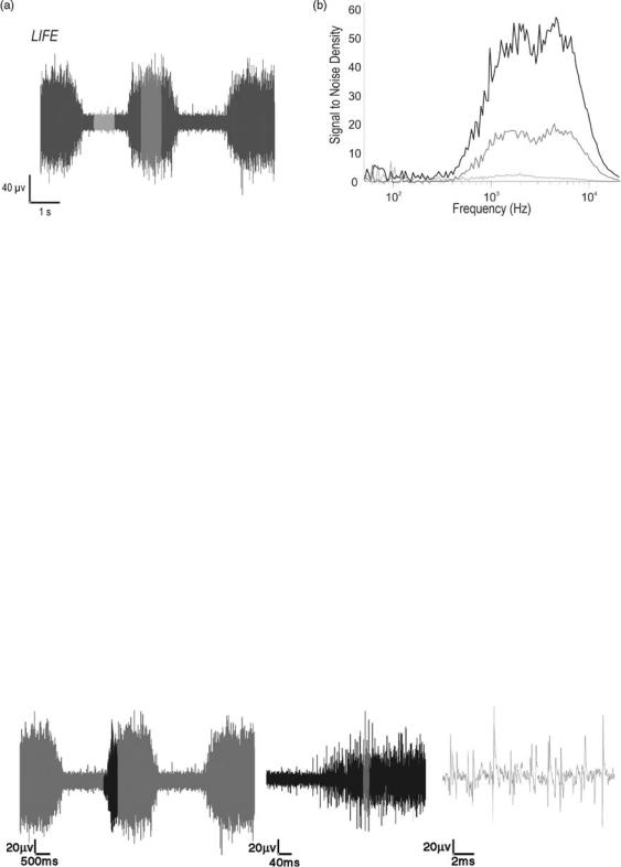
Intrafascicular electrodes place their recording sites within the nerve fascicle, but outside of the nerve fiber. The site can be potentially adjacent to an active nerve fiber. An ENG record from an intrafascicular electrode placed in a branch of the tibial nerve in the rabbit model is shown Fig. 3. The record shows the activity from many active nerve fibers firing asynchronously from one another and superimposed upon one another.
112 ELECTRONEUROGRAPHY
Figure 3. (a) Shows the raw record from a LIFE implanted in a medial gastrocnemius nerve branch of the tibial nerve in response to ankle flexion and extension. (b) Shows the spectral composition of the modulated LIFE activity for three different levels of activity starting from baseline, the lowest, to maximum, the highest. It illustrates that the amplitude of the spectral composition varies with the amount of activity, but the distribution remains constant.
If a closer look is taken of this multiunit activity recording, it is possible to see the spiking activity of single nerve fibers, or single unit activity. Analysis on the largest of these single spikes reveals that the amplitude of the activity is on the order of 10–100 mVpp. The spectral components of intrafascicular ENG records show that, similar to extrafascicular ENG records, the activity has energy starting at ca. 100 Hz. However, unlike the unimodal extrafascicular ENG spectrum, the intrafascicular ENG spectrum is bimodal, with higher frequency components in the 5– 10 kHz range (30) (Fig. 4).
Whether the ENG signals are recorded from extrafascicular or intrafascicular electrodes, it can be seen that ENGs are low amplitude signals and require amplification of between 1000 and 100000 to bring the amplitude into the 1 V range where they can be adequately digitally sampled and stored, or recorded on analog tape. Approximate orders of magnitudes of various signals and their approximate spectral frequencies that might appear in an ENG record are shown in the Table 1.
Given the amount of amplification required and the relative amplitudes of the ambient noise that could be
picked-up by the recording electrodes, recording configurations and filtering must be considered to minimize the noise pick-up and maximize the neural signals.
Recording Configurations
Components of a Recording Setup. The previous section gave the theoretical basis of how the action potential is generated and how this, in turn, results in a change in the electric field in the extracellular space. These potentials can, in turn, be detected using a combination of electrodes placed in or around the nerve, and recording instrumentation. A typical recording setup consists of the following components starting (from the input biological input end and working toward the data storage or output):
Electrodes: The active electrode(s), the ground electrode.
Differential preamplifier. Main-amplifier and signal conditioning. Digitization, Interpretation, and storage. Visualization and audio monitoring.
Figure 4. The figure shows an ENG recording in response to repeated mechanical activation of muscle afferents by stretching the muscle at various time scales. The amplitudes in all three traces are the same. (Left panel) Trace is the lowest time resolution and the right trace has the highest time resolution. The darker portion of the left trace is shown in the middle trace, which is zoomed in time by a factor of 12.5. The highlighted portion of the middle trace is represented in the right trace, which is zoomed in time by a factor of 20. (Right panel) Trace single spikes are now resolved, while in the other two traces only the gross mass activity can be resolved.
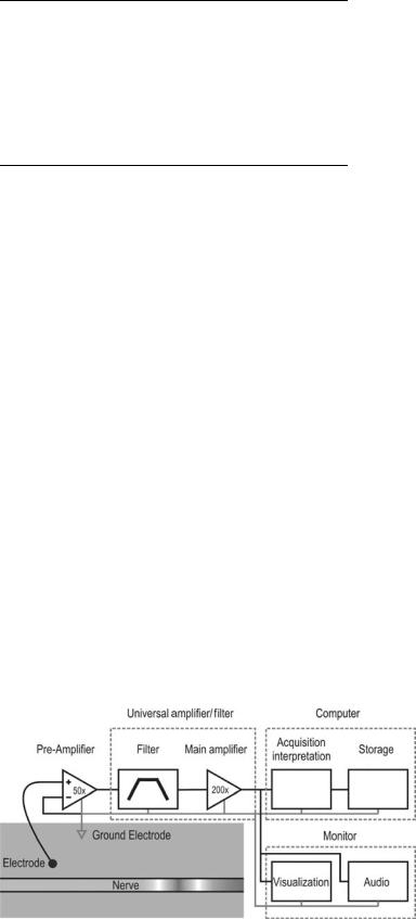
Table 1. Relative Amplitudes and Frequency Ranges of Components of Signals and Noise that Could Be Present in ENG Records
|
|
Amplitude |
Frequency |
Source |
Order |
Range |
|
|
|
|
|
|
Electrochemical potential |
1 V |
dca |
|
Motion artefact |
100 mV |
Broad |
|
Line noise |
10 mV |
50–60, 100–120 |
|
Thermal (electronics) |
10 mV |
Broad |
|
Electrocardiogram (ECG) |
1 mV |
0.1–100 Hz |
|
Electromyogram (EMG) |
1 mV |
1–1 kHz |
|
Electroneurogram (ENG) |
10 mV |
100–10 kHz |
|
Electroencephologram (EEG) |
1 mV |
dc–1 Hz |
aDirect current ¼ dc.
This instrumentation chain is represented schematically below in Fig. 5.
The components of the instrumentation chain can be blocked into four blocks: Preamplifier, Universal Amplifier/Filter, Computer, and Monitor. The preamplifier accepts signals from the electrode. Its function and configuration will be discussed in detail below. The Universal Amplifier/Filter block performs the analog filtering and main amplification, to reduce out of band noise, antialias and further amplify the signal and prepare the signal for the next block. The Computer block performs the digitization interpretation and depending on the application, storage of the neural data. It extracts and stores the information in the neural signal. Parallel to this is a monitoring block, which provides real-time feedback to the experimenter on the quality of the data being collected. In some cases, the monitoring block could be part of the Computer block. Neural signals are conveniently in the audio range, and the quality of the recording can be very effectively evaluated by simply listening to the signal through an audio monitor.
Differential Preamplifier. The differential preamplifier is a key component used in all measurement schemes. This component can also be called the headstage amplifier, preamplifier, or bioamplifier, and so on. In the context of biopotential recordings, the preamplifier is a low noise amplification stage used to amplify biopotentials to voltage levels in which signal conditioning can be performed using standard filters, amplifiers, discriminators, and so on. It
ELECTRONEUROGRAPHY 113
also serves the purpose of impedance matching between the relatively high impedance electrodes at its input and the relatively low impedance input of standard instrumentation.
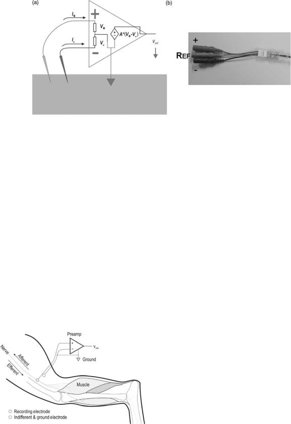
Differential preamplifiers can be described as an active (powered), three input ( reference), one output device. Its main function is to measure a potential at each of its two active input relative to a reference potential measured at the ground input terminal, take the difference of the measured potentials and multiply by a fixed gain. In equation form, it performs the following function:
vout ¼ A2 ½A1ðvþ vref Þ A1ðv vref Þ&
A typical differential preamplifier fitted with a standard connector is shown in Fig. 6 (b), though in practice packaging, connector and form factor for different preamplifiers vary widely. Common to differential preamplifiers are the three input terminals, and one output terminal. Although they can be realized using discrete components, most differential preamplifiers are realized using low noise instrumentation amplifier chips. Since the electrodes
attached to the vþ, v , and vref terminals of the instrumentation amplifier are physically located in different places;
this equation implies that a spatial derivative is performed. It can also be seen that the voltage at the reference terminal is common to both active input terminals and should ideally be rejected along with the common mode rejection capabilities of the amplifier, measured by the common mode rejection ratio, CMRR.
One factor, which has a strong influence on the recording performance, is the impedance match of the electrodes at the active input terminals. In voltage controlled voltage source amplifiers the input impedance is much larger than the impedance of components (the electrode þ tissue) preceding it so that most of the voltage drops across the input impedance of the preamplifier, and the voltage is adequately measured without attenuation. At the same time, there must be a finite dc current path from the input of the amplifier to ground to supply the required bias current to the input of the amplifier. Since there are no dc components in the extracellular nerve action potential, a commonly used scheme is to capacitively decouple the input to the amplifier. However, mismatches in the impedance of the electrode seen at each terminal of the amplifier can result in degradation of the CMR capacity of the amplifier.
Figure 5. A generic instrumentation chain consisting of a preamplifier that impedance matches the recording electrode to the relatively low impedance filter–ampli- fier chain, a bandpass filter, main amplifier, data storage and monitoring. Shown also is the grounding configuration of the instrumentation attached to a ground electrode in the tissue.
114 ELECTRONEUROGRAPHY
Figure 6. (a) Shows a schematic representation of the differential preamplifier and its electrode connections when used as a bioamplifier on tissues. (b) Shows a low noise differential preamplifier that could be used to record neural activity with a low impedance electrode.
Though the voltage, the controlled voltage source preamplifier scheme is the most commonly used type in current systems, current mode amplifiers, such as the application of microphone transformers have also been successfully used (31). The main limitations to the transformer amplifier scheme are the physical size of the transformer, which precludes their use in multichannel recording systems, and the necessity to carefully match the electrode impedance and transformer bandwidth.
Monopolar. Figure 7 shows the simplest recording configuration, the monopolar recording configuration where the activity recorded from the þ terminal of the preamplifier is amplified relative to a common reference electrode. Though the recording, configuration is commonly used for recording EEG, in vitro electrophysiological preparations and implanted cortical signals, the monopolar recording configuration would be sufficient to record activity from the peripheral nerve only in the ideal noisefree case.
In practice, peripheral nerve electrodes, unlike the surface EEG electrodes on the scalp, or intracortical electrodes, are implanted and used on or in nerves that are
Figure 7. The monopolar recording configuration consisting of a recording electrode on or in the peripheral nerve and a common indifferent/ground electrode.
generally surrounded by large biological noise sources, such as nearby skeletal muscles or the heart. As seen in the previous section, these bioelectrical sources have amplitudes that are orders of magnitude larger than the nerve signal, whose spectral domain can overlap that of the nerve activity making it difficult to filter the unwanted EMG activity out of the recording. Altering the recording configuration can reduce the pick-up of these unwanted activities. The monopolar recording configuration could be modified so that the reference electrode is place very close to the recording electrode, but far enough away from the nerve so that it only samples the unwanted EMG activity in the vicinity of the recording electrode.
The pick-up of unwanted radio-frequency (RF) noise, such as line noise, through the lead wires between the electrode and the amplifier, is a second problem. To adequately ground the recording system, the reference must have a low impedance dc path between the tissue and the electronic ground points. By necessity, the reference electrode should have a large area. The recording electrode, on the other hand, must sample the electric potential from a small area of nerve in order not to short out the nerve activity. The relative impedance of the recording and reference electrodes is not balanced, making the RF pick-up in each of these two electrodes leads different, and not cancelled by the CMR of the differential amplifier.
Another problem with the monopolar recording configuration arises when one wants to record from more than one channel. To minimize the pick-up of local EMG activity, one might use multiple recording and ground electrodes. However, in general, it is not good practice to have multiple ground electrodes in a single recording set-up (see Fig. 12). Each ground electrode represents a low impedance electrical pathway, through which large stray ground loop currents might pass. Such currents could exist during electrical stimulation or accidental electrocution.
Bipolar. The bipolar recording configuration overcomes many of the problems of the monopolar recording configuration and is the most commonly used recording configuration for most neural electrodes excluding cuff
ELECTRONEUROGRAPHY 115
Figure 8. Bipolar recording configurations. (a) Shows a standard bipolar configuration where the signals from one recording electrode are amplified with respect to a second electrode that samples the ambient noise, the indifferent electrode. A separate ground electrode is placed somewhere in the tissue. The differential bipolar recording configuration (b) places a second recording electrode in or on the nerve and the difference of the signals from two active electrodes is amplified.
electrodes. The bipolar recording configuration requires two recording electrodes and a low impedance reference electrode. The second recording electrode is matched to the first recording electrode and is introduced to sample the local noise in the vicinity of the first recording electrode. The two recording electrodes are attached to a differential preamplifier, which amplifies the relative difference of the potentials seen by the first electrode and those seen by that of the second electrode. Thus, the local EMG activity is seen by the differential preamplifier as common mode and is rejected. Similarly, since the two recording electrodes are matched, the RF noise induced on their lead wires is similar and is rejected by the preamplifier. The second electrode effectively samples the noise, but not the neural signal, and is referred to as the indifferent electrode (Fig. 8).
A variation on the bipolar recording configuration is the differential bipolar recording configuration. In this configuration, a second active recording electrode is introduced in or on the nerve instead of an indifferent electrode reducing the total number of electrodes that needs to be implanted. Additional channels can be introduced with the addition of matched recording electrode pairs and their associated preamplifier. Each additional preamplifier shares a common reference electrode to maintain only one low impedance path to ground, and minimizing the hazards of ground loops (see below).
The neural component of the potentials recorded by the electrodes is generated by a traveling waveform, which appears at the different recording sites along the nerve at different times. Thus, there are some consequences in using the differential bipolar recording configuration to the shape of the recorded action potential. Because the action potential is a traveling waveform, measuring the action potential at two different locations along the nerve and taking the difference, v(t1,s1) v(t1,s2), can be related to measuring the action potential measured at one location but at two different times, v(t1,s1) v(t2,s1). This relationship assumes that the two electrodes record the action potential equally, and the distance between the recording
sites are appropriate. v(t1,s1) v(t1,s2) is Dv/Ds, while v(t1,s1) v(t2,s2) is Dv/Dt. The relationship between the space interval, Ds, and the time interval, Dt, is the conduction velocity of the action potential, Ds/Dt. Therefore, the shapes of action potentials recorded using the differential bipolar configuration are roughly the derivative of the action potential recorded using the monopolar configuration. This alters the generally monophasic action potentials recorded by monopolar recordings to biphasic action potentials.
There is a dependence on the amplitude of the recorded action potential with the spacing between electrodes. The amplitude increases with electrode spacing until the spacing approaches the wavelength of the action potential. The wavelength of the action potential is dependent on the conduction velocity, which is related to the caliber of the nerve fiber. In general, distances should be kept > 1 cm for cuff electrode recordings (32), and > 2 mm in the case of differential bipolar recordings with LIFE (33).
Tripolar. The tripolar configuration is the most commonly used recording configuration with the nerve cuff electrode. The nerve cuff electrode is an extrafascicular recording configuration which places the active recording sites outside of the nerve fascicle. Since the perineurium has a relatively high impedance, most of the current generated by the nerve fiber during an action potential is restricted to within the fascicle. To maximize the signals, the nerve cuff design surrounds the nerve bundle with an insulating silicone tube that restricts whatever current leakage from the nerve bundle to the space between the nerve bundle and the insulating cuff. Let us first consider a cross sectional schematic of the electrode structure with a bipolar recording scheme as shown in Fig. 9.
One particular advantage of the cuff electrode is that the electrode is generally immune to noise sources that are lateral to the nerve and cuff electrode since they produce electrical fields that are shielded by the nerve cuff and shorted by the circumferential recording site of the electrode. However, noise sources producing electrical fields
116 ELECTRONEUROGRAPHY
Figure 9. Bipolar differential recording scheme used with the cuff electrode. The insulating cuff restricts the current from the nerve bundle to within the cuff to maximize the voltage generated from the nerve.
that are perpendicular produce a gradient through the nerve cuff, which is amplified by the bipolar recording configuration.
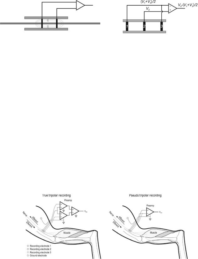
The tripolar recording configuration is a means to reduce or eliminate the longitudinal potential gradients of noise sources outside of the cuff. Two variants of the tripolar configuration are shown below in Fig. 10.
Longitudinal potentials from sources outside of the nerve cuff are influenced by the insulating cuff and linearlized within the cuff. The tripolar recording configuration takes advantage of this property and averages the potentials seen by the outer two electrodes to predict the extracuff noise potential seen at the central electrode, either by directly measuring and averaging the signals, as in the True Tripolar configuration, or by shorting the contacts of the outer two electrodes, as in the Pseudo-Tripolar configuration (shown below in Fig. 11).
The tripolar recording configuration introduces another differentiation operation on the shape of the action potentials recorded, and action potentials recorded with the tripolar recording configuration are triphasic.
Cabling. The cabling between the electrode active site and preamplifier is a major source of noise that can be minimized by taking care during cabling. Line noise and RF noise is induced in the leads between the electrode and the preamplifier since they act as antennae. The effect is similar to that with high impedance wired microphones.
Figure 11. Tripolar recording configuration in a cuff electrode.
Similar strategies could be used to reduce noise pickup. Lead lengths should be kept as short as possible, though, in the case of implanted electrodes, this may not always be practical or possible since cables from multiple locations are often bundled together and routed to a common percutaneous connector to minimize the number of holes through the skin. Another strategy is to twist the differential lead pairs together so that the noise induced in each pair is nearly the same and can be reduced using the CMR of the differential pre-amplifier. When appropriate, shielded cabling could be further be used, though care should be taken to minimize ground loops when multiple shielded cables are used.
Grounding. A critical factor influencing the quality of the ENG recording is how the system is grounded. A low impedance path to ground must be established between the preamplifier and tissue to keep the input stage of the preamplifier stable and out of saturation. In acute animal preparations, the experiment is commonly performed on a conductive metal surface, which is tied to ground to a common internal ground electrode to reduce line noise. In chronic animal experiments as well as in human implanted systems, this means to reduce noise is not an option since the subject is autonomous and freely moving. In this case, a ground electrode with large surface area, such as braided stainless steel shields, can be used to establish a single ground point to the tissue. Because the ground electrode is intended to provide a low impedance pathway to a ground potential, the ground electrode
Figure 10. Tripolar recording configurations. (Left panel) Shows the true tripolar recording configuration consisting of a double differential amplification circuit. (Right panel) Shows a pseudo– tripolar recording technique, which approximates the true tripolar recording configuration by shorting the outer two electrodes 1 and 3.
provides a reference 0 potential in the tissue, and the potential of the tissues immediately surrounding the ground electrode forms a 0 isopotential. Multiple ground points to the tissue are typically not a good idea since each ground electrode would have a different chemoelectric potential even if they are made of the same material, and currents would flow from ground electrode to ground electrode to maintain a 0 isopotential at each ground point.
The issue of ground loop currents is particularly a problem when stimulation is performed at the same time as recording and if the stimulator shares the same ground with the recording circuit. Since each ground electrode is at the same potential, the current from a stimulator can flow into one ground electrode and out of another ground electrode, as shown in Fig. 11, making it nearly impossible to predict the current flow and location of stimulation. If the magnitude of stimulation is large, such as with surface stimulation, a significant portion of the current could flow through the ground electrodes since the impedance of the tissue and stimulating electrodes can be considerably higher than the impedance of the ground electrode and ground line. Current flow through the ground line can result in large artifacts and potential damage to high gain amplifiers.
One strategy to reduce ground loop currents especially during stimulation is to electrically isolate different circuits from one another. Circuits, such as the analog amplifier chain that demand low noise, are kept physically in different subcircuits from circuits that are noise-producing, such as stimulator circuits or digital circuits. If these different types of circuits must reside on a common PCB or ASIC, Parallel or Mecca grounding schemes with ground planes surrounding each circuit type can be established to prevent noise from spilling over and interfering with noise sensitive parts of the circuit (34). The strategy applied to Functional Electrical Stimulation (FES) systems where stimulation and recording sites are in close proximity to one another is to electrically isolate the stimulating circuit from the recording circuit. This makes each circuit independent from the other so that currents originating from the stimulation circuit see a high impedance pathway with no return current path in the recording system (Fig. 12).
Figure 12. Illustrates potential ground loop currents that can be induced during stimulation if multiple ground electrodes (shown as triangles) are used. Since each ground electrode represents the same potential, the nearest ground electrode can draw current, which passes through the ground plane and out of the other ground electrodes, increasing the uncertainty of the point of stimulation.
ELECTRONEUROGRAPHY 117
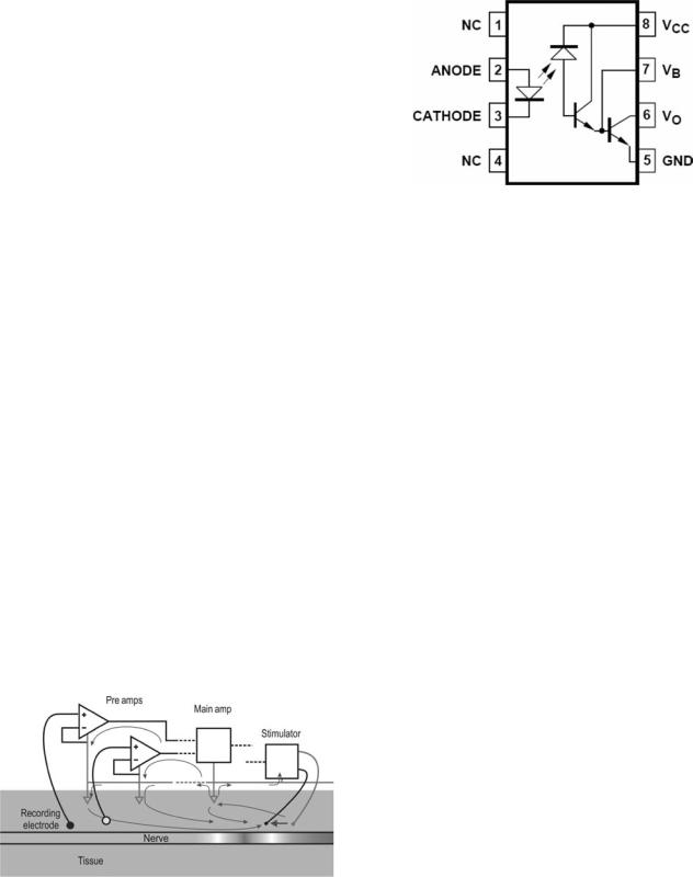
Figure 13. Schematic of a typical optoisolator using diode–diode coupling.
Optoisolators. An effective means to isolate circuits is with optoisolators. Optoisolators consist of two electrically independent halves: a transmitter, and a receiver. The basic analog optoisolator transmitter translates electrical currents into light intensity, typically through an LED. The transmitted light is detected with a phototransistor or photodiode receiver, which gates a current in the receiver that is mapped to the transmitter light intensity (Fig. 13).
If the transmitter and receiver are independently grounded and powered, this combination of optical transmitter/receiver electrically isolates the circuits at its input and output. This, of course, implies that when using optocouplers, each isolated circuit must have its own power supply and ground. The unisolated receivers can share a single power supply. A point should be made here about the number of ground electrodes in a recording set-up using multiple isolated recording/stimulation circuits. Since each isolated circuit must have its own ground, if several optoisolated recording/stimulation circuits are used, then each independent circuit must have its own single ground electrode. Ground loops between the circuits cannot form because the grounds are independent from one another, and there is no low impedance return path for ground loop currents to follow.
The optocoupler shown in the above Fig. 13 is a nonlinear device that is dependent on the coupling of the diode characteristics of the transmitter and receiver. Linear analog optocouplers also exist that linearizes the diode characteristics using feedback with a diode-transistor coupling instead of the diode–diode coupling. The diode–diode coupling, though nonlinear, has a relatively fast response time, with rise and fall times on the order of 2 ms. The diode-transistor coupling scheme, however, is bandwidth limited to considerably < 10 kHz. Newer linear optocouplers attempt to overcome the bandwidth limitation by sampling and flash converting the input voltage to a digital value, transmitting the digital value and reconstructing the analogue value with a DAC (Fig. 14).
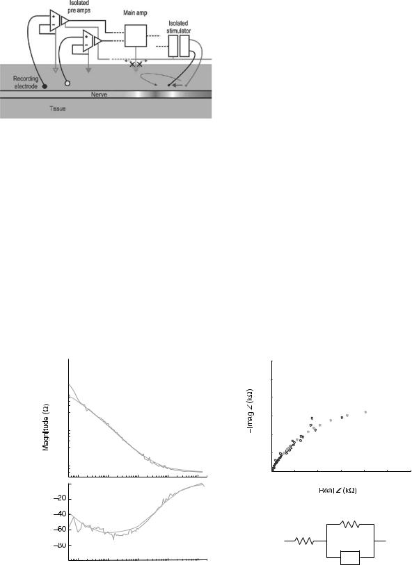
Electrode Impedance
Frequency Dependence of the Impedance. The impedance of the electrode is a function of the electrochemical properties of the electrochemical interface. Further discussion on the electrochemical interface and impedance can be
118 ELECTRONEUROGRAPHY
Figure 14. Use of optoisolated amplifiers and an optoisolated stimulator eliminates the ground loops shown in Fig. 8 by eliminating low impedance return paths to the tissue or stimulator circuit. Note that each isolated subcircuit has its own independent ground. Moreover, since there is no current flowing through the main ground from the tissue (shown as a dashed triangle), the main ground does not need to be grounded to the tissue.
found in other sections of this volume and in Grimnes and Martinsen (35).
A typical impedance spectrum for a platinum electrode is shown in Fig. 13. Though the absolute magnitudes of the impedance will vary depending on the total area of the electrode active site and the material used, this figure shows the general shape and characteristics of the impedance spectrum. Depending on the type of electrode used, the upper corner frequency and the lower corner frequency can be shifted. Similarly, the low frequency and high
frequency segments (the segment < 1 Hz, and > 1 kHz, respectively, in Fig. 15) can be higher or lower than shown.
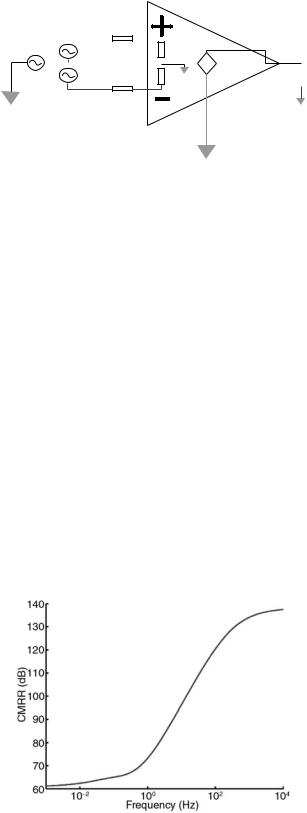
As seen earlier, most recording configurations rely on the common mode rejection ratio, CMRR, of the differential preamplifier to reduce noise pick-up and maintain stability of their neural recording. One consequence of the frequency dependence on the electrode impedance is that it influences the common mode rejection ratio. The differential preamplifier and its input can be represented by the following, where Vcm represents the common mode noise, which is to be rejected, and Vdm represents the differential nerve signal, which is to be amplified (Fig. 16).
Assuming an ideal preamplifier where the two input resistances Rinþ and Rin are equal, and applying the differential preamplifier equation given earlier, the common mode rejection ratio can be represented by
CMRR |
|
|
Adm |
|
|
|
þ |
|
2R |
|
|
|
|
|
|
|
|
|
|
|
|
|
¼ |
|
Acm |
|
¼ |
|
Z |
Z |
|
|
|
|
|
|
|
|
|
|
|
|
|
In the ideal case, where the electrode and tissue impedances are matched, then the CMRR for an ideal differential preamplifier becomes infinite. However, real electrodes are relatively difficult to match, especially when dealing with small, high selectivity active site electrodes. A 10% error in electrode impedance at 1 kHz is common even with matched electrodes. Based on the CMRR equation and typical impedance shown earlier, the CMRR dependence versus, frequency can be calculated (Fig. 17).
It shows that because of the relatively high R0 impedance at low frequency, there can be degradation in the CMRR, which results in inclusion of some of the relatively
(a)
105 
104 
103 
0
Phase (Deg.)
10° |
101 |
102 |
103 |
104 |
Frequency (Hz)
(b)
60 |
|
|
|
|
|
|
50 |
|
|
|
|
|
|
40 |
|
|
|
|
|
|
30 |
|
|
|
|
|
|
20 |
|
|
|
|
|
|
10 |
|
|
|
|
|
|
0 |
|
|
|
|
|
|
0 |
10 |
20 |
30 |
40 |
50 |
60 |
(c)
R0-R∞
R∞
CPE
Figure 15. (a) Shows a typical metal electrode impedance spectrum and its fit to the Cole model shown in (c). (b) is the Warburg representation of the impedance spectrum where the real Z is plotted with respect to the negative of the imaginary Z.
Z +
|
|
vdm/2 |
|
|
|
V+ |
|
|
|
|
|
||||
|
|
Rin+ |
|
||||
|
|
|
|
|
|
+ |
A*(V+-V-) |
|
|
|
|
|
|||
|
|
vdm/2 |
|
|
− |
||
|
|
|
|
||||
vcm |
Rin- |
vout |
|||||
V-
Z -
Figure 16. Shows a model of the differential preamplifier and its connections to input impedance loads, common mode, and differential mode inputs. The common mode input can represent noise that we hope to exclude from the ENG while the differential mode input represents the neural signal. The input Z represents the tissue, electrode, and whatever input network is used between the amplifier input and the signal sources.
high amplitude noise that exists at these frequencies. Similarly, not all of the ECG and EMG will be rejected. Therefore, inclusion of noise components from these sources should be expected in the raw ENG record and must be filtered before analysis and use of the ENG can be considered. High pass filtering the output of the differential preamplifier can remove much of the out of band noise not rejected by the CMR of the differential amplifier, but care should be taken to ensure that the differential preamplifier is operating within its linear dynamic range.
EXAMPLES OF LONG-TERM PERIPHERAL NERVE INTERFACES
Peripheral neural electrodes can be grouped according to the way that they interface with the peripheral neural tissue. They can be grouped into three main types: regenerating, intraneural, and extraneural electrodes. Common for all electrode interfaces presented here are that they
Figure 17. The frequency dependence of the CMRR is shown for an ideal preamplifier using electrodes that are mismatched by 10%. The frequency dependence of the electrodes has a large influence in the CMRR, which resembles the inverse of the electrode impedance.
ELECTRONEUROGRAPHY 119
record the extracellular potential from one or more peripheral nerve axons simultaneously (also referred to as extracellular electrodes). A fourth electrode group aims instead to record the intracellular potential of individual cells (also referred to as intracellular electrodes). In this case, the active recording site is placed inside a cell, so the electrode must therefore be carefully positioned and held in place during the entire duration of the recording. With their use, there is the risk of permanently breaking the membrane and injuring or killing the cell. As such, intracellular electrodes can be used acutely in vitro, in situ, or in vivo, however, they are not suitable for chronic animal, human or clinical use because of mechanical stability issues and the unavoidable damage to the cells that they record from. These electrodes are therefore not considered further here.
The choice of an optimal peripheral neural electrode largely depends on the application or the experimental design. One electrode might prove useful for one purpose, but not for suitable for another. A vast number of parameters have been used in the literature to describe, characterize, and compare neural interfaces. Most electrode interfaces can not only be used for recording from peripheral nerves, but also for applying electrical stimulation to the nervous tissue. However, the focus here will be on peripheral neural interfaces for recording. To provide a base for comparison between electrode types, the discussion will focus on the following issues:
Design parameters, including: The rationale for design, the ease of use and the cost of manufacturing and ease of implantation.
Application of the electrode, including: Recording selectivity and recording stability, expected lifespan, biocompatibility and robustness, and application examples.
Regenerating Electrodes
Introduction. Peripheral nerve axons spontaneously regrow after dissection or traumatic injury. The working principle of a regenerating electrode is to fit an electrode in the path between a proximal and distal nerve stump after a deliberate cut or traumatic nerve injury, and to guide the neural regrowth through perforations in the electrode structure. Ideally, the axons will grow through the perforations and allow very high resolution (single axon) recordings.
Sieve Electrodes
Design. Regenerating electrodes are often referred to as Sieve electrodes, inspired from their appearance. The structures are typically based on a sieve-shaped or perforated diaphragm, which contains an array of holes. The active sites are placed inside the sidewalls of the hole or in their immediate surroundings (similar to a printed circuit board via) to make physical contact with an axon growing through the hole. They are often designed incorporating a used small flexible tube made of a biocompatibile material (e.g., polyimide or silicone) that is used to hold the two ends of the transected nerve stumps in place with the sieve
120 ELECTRONEUROGRAPHY
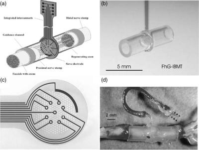
Figure 18. (a) Sketch of a Sieve electrode. The proximal and distal nerve stumps are fed into a guide tube. Neural axons must grow through holes in the Sieve electrode to reconnect with the neural axons on the other side. (b,c) Examples of Sieve electrodes. (d) shows the Sieve electrode in situ. (Reproduced with permission from T. Stieglitz, Fraunhofer Inst., Germany.)
electrode structure fixed in place between them. The tubes work to help guide the growing axons and to hold the electrode structure in place (36) (see Fig. 18). The first generations of Sieve electrodes were developed more than two decades ago (37). With the development of micromachining techniques, the devices have become considerably smaller and further enabled more suitable connections between the electrode and the surrounding world (38). These newer generations of sieve devices are made of silicon (39–41), polyimide or silicone substrates (38,42). Sieve electrodes have been designed with various shapes of the holes [round (40), squares (43), or longitudinal slots (39)]. The shape of the hole does not seem to have a major effect on the regrowth of the axons (36), but other design parameters, (such as the hole size, the thickness of the sieve diaphragm, and the relative amount of open versus closed space (also referred to as the transparency factor) have been found to be important. The thickness of the sieve diaphragm is typically in the order of 4–10 mm (36,40,41). Several findings suggest that 40–65 mm diameter Sieve holes work well (41,43,44), however, Bradley et al. (41) found that the holes could be as small as 2 mm. This may be explained by the difference in transparency factors of the electrodes. A high transparency factor is needed if the holes are small to secure regrowth (45). Major effort has also been put in to researching the use of neural growth factors (NGF) and how these may assist in promoting the spontaneous regeneration, and this may become an important factor in the future success of the Sieve electrodes.
Application. Bradley et al. (46) was among the first that obtained long-term recordings using sieve electrodes in mammals. They recorded from the rat glossophraryngeal nerve, which is mainly sensory, mediating somatosensory and gustatory information from the posterior oral cavity. Spontaneous activity was observed up to 7 weeks after implant. Evoked compound sensory responses were recorded up to 17 weeks after implantation. Other longterm evaluation studies have been reported by, for exam-
ple, Mesninger et al. (42,47,48). Despite the growing number of reports on long-term usage of Sieve electrodes, they have not yet been tested in humans. An ideal axon-to-axon reconnection through a Sieve electrode could provide the ultimate interface to monitoring peripheral neural activity, but to date, this concept has not been proven in humans. Deliberate transection of a peripheral nerve to allow implant of a sieve electrode is a highly invasive procedure, and the success of the implant can only be evaluated several weeks after implantation (36). The current designs are not optimal since some axons may stop grow when the meet a wall and not a hole (36). Furthermore, it is currently not possible to control what fiber types regenerate. It has been shown that myelinated fibers are more likely to grow through than unmyelinated fibers, and large fibers are more likely to grow through than small fibers (49). It will be necessary to obtain a detailed map of what kind of sensory or motor axons have reconnected in order to interpret the peripheral neural signals properly (Fig. 19).
Intraneural Electrodes
Introduction. Intraneural electrodes are defined as electrodes that penetrate the endoneurium and perineurium of a peripheral nerve or the dorsal root ganglion (DRG) neuropil. The active sites are placed in the extracelluar space in close proximity with the nerve fibers, and therefore the electrodes aim to record from one single axon or from a small population of axons. The intraneural, penetrating electrodes are dependent on the insulating properties of the epineurium/perineurium to record.
Microneurography. Microneurography is a procedure in which a small needle electrode is placed directly inside a nerve fascicle. The aim is to record from one axon or a small a population of axons to study basic neural coding in the animal or human subjects, or as a diagnostic tool in clinical practice. Sketches of two types of microneurography electrodes are depicted in Fig. 19.
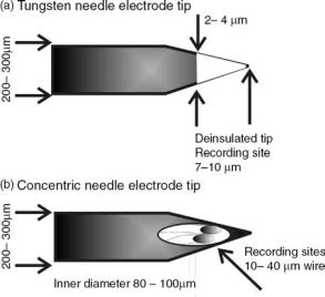
Figure 19. Microneurography electrodes. (a) A drawing of the geometry of a typical, commercially available tungsten needle electrode. A separate ground or indifferent electrode must be place in the close surroundings (Drawings appear courtesy of Dr. K. Yoshida.) (b) A drawing of a concentric needle electrode. One or two fine wires are threaded through a hypodermic needle and attached
Design. A classic needle electrode is manufactured from a stiff core material (e.g., tungsten, stainless steel, or carbon fiber) surrounded by a layer of insulating material. The Tungsten needle electrode typically has a 200–300 mm base diameter and a 2–4 mm tip diameter to ensure that the material is stiff enough to be pushed through the skin and muscle tissue and enter the perineurium without damaging the tip. The needle tip is uninsulated to create the active site. A separate ground wire must be placed subcutaneously in the close surroundings of the recording electrode (50,51).
A variation of the classic needle electrode was developed to allow more recording sites to be placed inside the nerve. The concentric needle electrode consists of one or more fine recordings wires threaded through a hypodermic needle. The fine wires are glued in place with an epoxy adhesive. The wires are typically made from tungsten, platinum, or platinum–iridium, and have a 20–25 mm diameter that provides a smaller, and thereby more selective recording, site than with the Tungsten needle electrode. An active site is made at the end of the wire by simply cutting the wire at a straight or slightly oblique angle. The hypodermic needle has a typical outer diameter of 200–250 mm and an inner diameter of 100 mm. The hypodermic needle tip provides a cutting edge for easy insertion of the electrode. Further, the needle shaft works as the ground during recording (52).
The microneurography electrodes are implanted perpendicular to the nerve trunk, and they are typically inserted by hand or using a micromanipulator. These electrodes are inexpensive, and they are typically and both types are easily manufactured by hand.
Application. Since Vallbo and colleagues developed the microneurography technique for more than three decades ago, the technique has proved to be a powerful tool in
ELECTRONEUROGRAPHY 121
clinical experiments on conscious humans in hundreds of studies (51). However, the technique has a number of clear limitations. Placement of one single recording electrode may be extremely time consuming, and the delicate placement may easily be jeopardized if the animal or human subject moves. The microneurography needle electrodes are considered safe for short-term experiments, but they are not applicable for long-term implant and recording in animals or humans.
Longitudinal Intrafascicular Electrodes. The longitudinal intrafascicular electrodes (LIFE) are implanted parallel to the main axis of the peripheral nerve, and the active site of the electrode is placed along recording wires and not at the tip. The active sites typically record from a small population of axons.
Design. One of the first LIFE designs consisted of a simple 300 mm coiled stainless steel wire that was implanted into the nerve using a 30G hypodermic needle (53). The size of the hypodermic needle and implanted electrode may cause unnecessary injury to the nerve, and it also made it unsuitable for implantation in small nerves. Pioneering work was later done at University of Utah, as an attempt to solve these problems. A metal-wire LIFE was developed, see Fig. 21b (54). Here the 1–2 mm recording sites are created on 25 mm insulated, platinum– iridium wire. The recording wires are soldered to larger stainless steel lead-out wires, and the connections are protected by sliding a silicone tube over the solder joint. A polyaramid strand is threaded through this loop and glued to a 50–100 mm electrosharpened Tungsten needle (much similar to the tungsten needle electrode shown in Fig. 19). The needle is used to penetrate the perineurium/ epineurium and pull the recording wires into place. The large lead-out wires remain outside the nerve. The electrode is sutured to the epineurium to hold it in place. The lead-out wires are then tunneled subcutaneously through the body to a chosen exit point. These metal-based LIFEs are relatively low cost, and they can be hand built. One of the disadvantages is the limited number of fine wires that can be fitted into one nerve. Further, the hand-building procedure does induce some variability in the size of the recording site, which influences the impedance and signal/ noise ratio.
Later generations include polymer-wire LIFEs. Instead of using platinum–iridium wire, the recording wires are here based on 12 mm kevlar fibers. A metal is first deposited onto the kevlar to make the wire conductive, and a layer of silicone insulation is then added only leaving the recording sites exposed (55,56). The purpose of decreasing the intrafascicular wire size was to make the wires more flexible.
Application. The development of the LIFE has mainly been driven by the need for alternative and safe neural interfaces for clinical neuroprosthetic systems. Goodall et al. implanted the 25 mm platinum–iridium wire LIFEs in cat radial nerves and demonstrated that it was possible to obtain selective recordings of afferent activity from up to 6 months (59). Yoshida et al. used the same types of LIFES for recording neural activity in chronically
122 ELECTRONEUROGRAPHY
Figure 20. (a) Placement of a metal-wire LIFE electrode inside a whole nerve fascicle. Only the fine wires with the active sites are threaded through the nerve whereas the remaining part of the LIFE is located outside the epineurium. (b) is a line drawing of a two-channel metal-wire LIFE electrode. (a) Lead-out wires are located outside the body and tunneled through the body to a chosen exit point. (b,c) A silicone-tube is places over the connection point for protection. (d) Active sites on the recording wires. (f–h) A polyaramid fiber links the recording wire to a tungsten needle. The tungsten needle is used to thread the fine wires through the nerve and is removed after implantation. (Courtesy of Dr. K. Yoshida, Aalborg University, Denmark.)
implanted cats. These studies characterized the effect of electrode spacing for rejecting EMG and stimulus artifacts and explored the possibility of using multichannel recordings for noise reduction. Yoshida and Stein (33) also explored the possibility of extracting joint angle information from muscle afferent signals recorded with LIFEs (6). The information was used as feedback in closed-loop control of the ankle joint in the cats. The chronic recording stability and biocompatibility of the polymer-wire LIFES have been demonstrated by Malstrom et al. (58) in dorsal rootlets and in peripheral nerve (59) (Fig. 20).
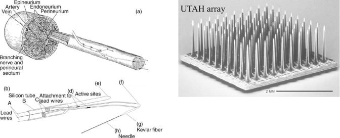
Silicon-Based electrodes. The design and manufacturing of silicon-based electrodes take advantage of often sophisticated microfabrication techniques. These electrodes may be inserted transversely into the peripheral nerve as the microneurography needle electrodes, or they may be inserted longitudinally as the LIFE electrodes. Many groups around the world have designed, developed, and tested different silicon-based electrodes, however, the vast majority of those are developed for interfacing with the cerebral cortex tissue. Many of these designs are currently considered unsuitable as chronic peripheral nerve implants because of the risk of mechanical failure of the rigid base structure or small, thin electrode shafts. A notable exception to this view is the Utah array. One electrode that has been used for both peripheral nerve and cerebral cortex implantation is presented here.
Figure 21. The 100-channel UTAH array. The electrode was originally developed at University of Utah, by Dr. R. A. Normann and colleagues. The electrode is commercially available through Cyberkinetics Inc. (Courtesy of Dr. R. A. Normann, University of Utah.)
Design. The UTAH array was originally developed by Normann and colleagues at University of Utah, and this electrode is now commercially available through Cyberkinetics Inc. The UTAH array is a three-dimensional (3D) silicon structure usually consisting of 100 penetrating electrodes arranged in a 10 10 array (see Fig. 21). Each needle is a long, tapered structure that is 1.5 mm long and has an 80 mm diameter at the base. The distance between the needles is 400 mm. The base substrate for this electrode is silicon, and glass is used as insulation material. Only the very tip of each needle is deposited with gold, platinum, or iridium to form the active site (59). Fig. 22 shows an array with equal height needles, which was originally designed for recording from the cerebral cortex where the neurons of interest are often located at the same depth. A slanted UTAH array was designed with different lengths of the needles to better target different layers in the cerebral cortex or to accommodate for the fact that fascicles in a peripheral nerve are located at different depths. Implantation of the UTAH array requires a special insertion tool that shoots the electrode into the neural tissue in a controlled manner. This is necessary because the high density of the needles increases the amount of force that is necessary to penetrate the dura or the epineurium. Further, the insertion tool avoids the elastic compression of the neural tissue and possibly damage of the neural tissue that was found during manual insertion (60).
Application. The recording properties of the Slanted UTAH array was first tested by Branner and colleagues in acute cat model (61,62) and later in similar chronic cat implants (2). The 100-electrode array was inserted in the cat sciatic nerve using the pneumatic insertion tool (described above). The acute work demonstrated that it was possible to achieve highly selective recordings with the array. In the chronic experiments, the array was held in place using a silicone cuff (self-spiraling or simply oval shaped) to protect the implant and surrounding tissue, to hold the implant in place, and to electrically shield the electrode. This containment was found to be important for the long-term survival of the electrode. In the chronic experiments, electrodes with lead wires were implanted
up to 7 months, however, it was only possible to obtain stable recordings for a few days after implant.
The slanted UTAH array has also been implanted in dorsal root ganglions (through the dura) in acute cat model to evaluate the neural coding of the lower leg position (10). In this work, it was possible to obtain selective recordings from the UTAH arrays over the duration of the experiment. The UTAH array has recently been implanted in a human volunteer (in a peripheral nerve in the lower arm), however, the results are pending (63). The UTAH array is also currently under clinical evaluation as a cortical interface in humans by Cyberkinetic, Inc.
Extraneural Electrodes
Introduction. The extraneural electrodes are the least invasive interfacing technique presented here. They are defined as electrodes that encircle the whole nerve or are placed adjacent to the nerve without penetrating the epineurium or dorsal root ganglion neuropil. The electrodes record from a large number of nerve fibers at the same time.
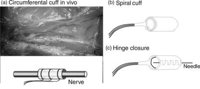
Circumferential Cuff Electrodes. The cuff electrode is probably the peripheral nerve interface that appears with the largest number of variations in designs and configurations. Only the main designs will be presented here. It is the most mature and widely used chronically implanted electrode for use in neuroprosthetics and has been used in a large number of animal studies and implants in human subjects (see section below).
Design. A circumferential cuff electrode consists of a tube or cuff that is placed around the whole nerve. The active sites are attached to the inside of the cuff wall to make contact with the epineurium (see Fig. 22). The tube wall works as an insulating barrier keeping extracellular currents emerging from the nerve within the cuff and blocking electric currents from other surrounding tissue (predominantly muscle activity, but also activity from other nerves) outside of the cuff. The tube wall has found to be essential to obtain measurable voltages from the
ELECTRONEUROGRAPHY 123
nerve trunk and to achieve a good signal/noise ratio. The cuff tube or wall is made of a flexible, biocompatible material, such as silicone, (1,64,65) or polyimide (66,67). The cuffs may be handmade or microfabricated. The microfabrication technique has the advantage that thinner walls can be obtained.
The shape and number of active sites placed inside the cuff wall vary. The active sites are typically made of inert metals, such as platinum or platium–iridium. In the classic configuration, a cuff electrode consists of a silicone tube lined with two or more thin conductive rings that are displaced from one another along their common axis (69). In this design, the number of active sites is usually three, but more may be fitted into the cuff depending on the application. The large conductive rings record from a large number of fibers within the nerve they encircle. Later designs placed several, smaller active sites around the inner cuff wall in an attempt to interface individual fascicles within the nerve trunk, and thereby increase the selectivity of the cuff recording (68,69). The number and size of the active sites have a large impact on the recording and stimulation selectivity, which will be discussed in the next section.
The cuff electrode is fitted onto a nerve by sliding the nerve into a longitudinal slit in the cuff wall while traction is placed on the cuff wall to keep the slit open. The procedure may be made easier for the experimenter/surgeon by gluing a number of sutures to the outside of the cuff wall (see Fig. 22a). The experimenter/surgeon can grab onto these sutures, pull the cuff open, and slide the cuff in place around the nerve. Knots are tied to close the cuff and secure that extracellular current is contained inside the cuff, which is important to achieve good recordings. Other closure mechanisms have been attempted.
1. A hinge or zipper-like closure has been suggested by Dr. M. Haugland, Aalborg University, Denmark [see Fig. 22c and patented by (70)]. Here the cuff is cut open and integrated with a piano hinge structure, that can be zipped up and threaded with a suture for closure. The disadvantage of this
Figure 22. The sketch representation of the cuff (around the nerve) electrodes (left) and the newly designed 12-contact circular cuff electrode (with a longitudinal slit) for selective stimulation with a four-channel stimulator. In order to minimize contamination of the neural signal from the surrounding biological signals, the electrode must fit tightly around the nerve and close well. An electrode can be closed with the flap covering the longitudinal slit, and kept in position by means of the surgical threads around the cuff (left side). It can be closed by using a ‘‘zipper’’ method where the ends of the cuff have little holes, through which a plastic baton can be pulled (right side). A self-wrapping polyimide multipolar electrode for selective recording/stimulation of the whole nerve is shown in (c). (Part a is courtesy of Dr. W. Jensen, Aalborg University, Denmark.) (Parts b and c are courtesy of Dr. T. Sinkjær and Dr. M. Haugland, Aalborg University, Denmark.)
124 ELECTRONEUROGRAPHY
Figure 23. Sketches of two cuff-electrode types that reshape the nerve. (a) The flat-interface electrode (FINE) has a rectangular shape and flattens the peripheral nerve in order to make selective contact with individual fascicles in the nerve. The active sites are placed on the cuff-wall. (b) The slowly penetrating interfascicular electrode (SPINE) is designed with a number of beams holding the active sites. A closure tube is moved over the beams to force the beams into position. The nerve will reshape around the beams and thereby make selective contact with the fascicles in the nerve. (Redrawn with permission from Dr. Durand, Case Western Reserve University.)
closure mechanism is that it adds several steps to the fabrication process. Furthermore, greater skill is required from the experimenter/surgeon for correct implantation and closure.
2.A second cuff is placed over the first cuff. This is an easy way to securely cover the longitudinal slit, and it is easy to implant. The disadvantage of this method is that overall implant diameter and stiffness increases.
The diameter of a fixed-sized cuff is an important design parameter. The inner diameter cannot be too large since the cuff wall works an electrical shield, and the active sites must make contact with the epineurium. It has been suggested that the fixed-sized cuff should have an inner diameter of 20–50% larger than the nerve to avoid postimplant nerve damage caused by edema or swelling of the nerve (1,32).
A spiral cuff or a self-wrapping cuff design was originally suggested by Naples et al. (71) to circumvent some of the problems with the fixed-sized cuff. The spiral cuff electrode consists of a planar silicone or polyimide sheeting containing the active sites. The planar sheeting is flexible and is designed to automatically coil around a peripheral nerve (see Fig. 22b). These electrodes are generally handmade, but also have been manufactured by microfabrication techniques. The electrode will make a tight connection with the epineurium, leaving no space between the nerve and the contact sites. The self-sizing property of this design provides several advantages; (1) It is not necessary to determine the cuff diameter in advance as it is with the fixed-sized cuff electrodes. (2) The coiling will automatically and easily close the cuff and hold the cuff into place, and it is therefore very easy to implant. (3) The coiling will provide the necessary constriction of the extracellular current emerging from the nerve fibers without any possible leakages. (4) The coiling will allow the electrode to change size to accommodate for possible edema in the days after implantation.
An example of a cuff-electrode design that incorporates a number of the already discussed principles is a design referred to as the polyimide-hybrid cuff electrode (69) (see Fig. 22d). The electrode is based on a polyimide spiral cuff design containing multiple, platinum contacts on the inner wall. The polyimide-hybrid cuff is manufactured using microfabrication techniques that makes it possible to place a relatively high number of contacts inside the cuff and at
the same time allow space for lead-out wires, which was a problem with the first multicontact cuffs. The microfabrication technique further secures high repeatability in the manufacturing process. Several patents on this type of hybrid fabrication has been issued (72,73).
Application. The first circumferential cuff electrode used for chronic recording was described by Hoffer et al. (74) and later by Stein et al. (75). It is to date the most successful and most widely used chronic peripheral interface in both animals and humans. An overview of current neuroprosthetic applications based on long-term recording from peripheral nerves is given elsewhere in this chapter. Many of these systems use cuff electrodes as their neural interface, and at the time of this writing, is the only implanted nerve interface being used in humans with spinal cord injury or stroke to provide FNS systems with natural sensory feedback information.
Reshaping Cuff Electrodes. The fixed-diameter, circumferential cuffs or the spiral cuffs have their active recording sites placed around the epineurium, and these electrodes therefore mainly record from the most superficial axons or fascicles. The reshaping cuff electrode attempt to accommodate for that by remodeling the shape of the nerve to access individual fascicles.
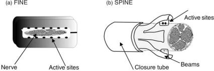
Design. Two types of reshaping cuff electrodes were developed by Durand and colleagues at Case Western Reserve University. In the slowly penetrating interfascicular electrode (SPINE) the active sites are placed inside the nerve, however, without penetrating the epineurium (76) (see Fig. 23). This is accomplished by a set of blunt penetrating beams that is slowly pushed into the nerve trunk by a closure tube. The active sites are placed on the side of the beams and may therefore access different fascicles of the nerve trunk. A refinement on this concept, the flat interface nerve electrode (FINE) was later developed (77). This electrode has a fixed shape like the fixed diameter, circumferential cuffs, however, the shape is rectangular instead of round (see Fig. 23). Ideally, the individual fascicles will then make contact with different contact sites along the cuff wall.
Application. The reshaping cuff electrodes were mainly developed as a stimulation platform; however,
Figure 24. A hook electrode consists of two simple wires/hooks that are held in close contact with the nerve surface. The picture shows an example of a custom made hook electrode. (Courtesy of Dr. K. Yoshida, Aalborg University, Denmark.)
both types could potentially be used for recording. Acute studies with the SPINE electrode show that the slowly penetrating beams can safely place active sites within the nerve trunk, and it is possible to selectively activate different fascicles of the nerve (77). One of the main design issues with the FINE electrode has been to choose the right size of the electrode without causing nerve damage. Animal studies have shown that the FINE electrode is suitable for both recording and stimulation in chronic animal implants (78,79).
The Hook Electrode. The hook electrode was among the first extraneural electrodes used in experimental neurophysiology and neuroscience. The hook electrode is not useful for long-term nerve implants, however, it is still widely used in acute animal experiments or as an intraoperative tool for nerve identification, and therefore a brief introduction is given here.
Design. The hook electrode is constructed of usually two or more hook-shaped wires that form the recording/stimulation sites (typical materials used are platinum, stainless steel, or tungsten) (see Fig. 24). The nerve trunk or fascicle is placed so the epineurium makes close contact with the hooks. The hook-wires are soldered to insulated lead-out wires that are used to connect with the recording/stimulation equipment. The lead-out wires are usually threaded inside a tube or glued onto a stiff rod to form a base for holding the hook electrode in place. The hook wires must be stiff enough to support the whole nerve or nerve fascicle without yielding. One of the main advantages of the hook electrode is that it is easily handmade at a very low cost.
Application. The distance between the hooks may be varied to change the electrical recording/stimulation properties, however, the relatively large distance between the active sites means that the electrode has a poor selectivity. To use the hook electrode, the whole nerve must first be made accessible in the body, and surrounding fascia must be dissected away to place the hooks underneath the nerve. To avoid electrical shunting between the hooks caused by the extracellular fluid, a paraffin oil or mineral oil pool is often created around the hook electrode and nerve in acute animal studies. For human experiment, the hook electrode and the
ELECTRONEUROGRAPHY 125
nerve may alternatively be suspended into the air to obtain a similar, insulating effect between the hook wires.
USE OF PERIPHERAL NERVE SIGNALS
IN NEUROPROSTHETIC APPLICATIONS
Traumatic or nontraumatic injury to nerves at peripheral, spinal, or cortical level may cause permanent loss of sensory and motor functions. The goal of neuroprosthesis applications is to replace, restore, or augment the lost neural function in order to regain the lost mobility or sensation. Popovic and Sinkjær (80) discussed clinical areas where FES is already important or where it holds great potential if the adequate technology will be developed. In the present section, the state-of-the-art of using information provided by peripheral nerve signals in preclinical evaluated and experimental neuroprosthetic applications will be discussed.
Neurorprostheses systems traditionally work by using functional electrical stimulation (FES) to elicit controlled muscle contraction. The functional electrical stimulation can be applied using an open- (feed forward) or a closed-loop (feedback) controller scheme. The open-loop systems have proven to work, however, since no regulation is provided, excessive stimulation and muscle fatigue are commonly observed. Once the stimulation has been determined in the open-loop system, it is not changed, and it is not possible to detect or account for unexpected events or external disturbances. Several studies have shown that the application of closed-loop control techniques can improve the accuracy and stability of FES activated muscles. However, the closed-loop systems are dependent on feedback on the current state of the part of the body under control. The availability of sensors to provide reliable feedback information is, therefore, essential. An illustration of the basic elements in a closed-loop FES control system is given in Fig. 25.
Artificial sensors placed outside the body have been used widely within closed-loop FES applications to provide the necessary feedback signals [e.g., including goniometers
Figure 25. Illustration of the basic elements in a closed-loop neuroprosthesis application. The instrumentation typically includes an external (i.e., outside of the body) command interface and control system and external/implanted interfaces for sensing or activating the biological tissue.
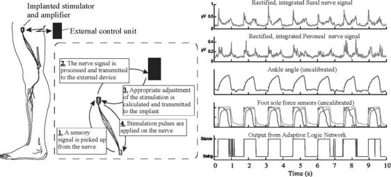
126 ELECTRONEUROGRAPHY
Figure 26. Footdrop correction system, using natural sensory information from the Sural or Peroneal nerve. The nerve signals were processed to determine heel contact with the floor and to decide the timing of the ankle dorsi-flexion stimulation. The stimulation may be applied through a peroneal nerve cuff electrode innervating the Tibials Anterior muscle or by surface electrodes. (Reproduced with permission from Dr. T. Sinkjær, Dr. M. Haugland, and Dr. M. Hansen.)
and accelerometers (80)]. However, the excess time consumed donning and doffing the artificial sensors, and the poor cosmetic visibility of bulky sensors has proven to be a major disadvantage for end user acceptance (1). Artificial sensors have also been placed inside the body; however, they require power to work and can be a problem to replace in case of failure.
The natural sensors, such as those found in, the skin (cutaneous mechanoreceptors, nociceptors), muscles (proprioceptors), or internal organs (visceral neurons) normally providing the CNS with feedback information on the state of the body. They are presently an attractive alternative to the artificial sensors in the cases where the sensors are still viable below the level of brain or spinal cord injury. Unlike artificial sensors, natural sensors are distributed throughout most of the body, and they do not require power or maintenance. Also, efferent motor signals are of interest to monitor the command signals from the CNS to the motor end organs. In many cases, they can be accessed through the same nerve based electrodes used for FES.
Therefore, the peripheral nerve signals of interest here are any neural tissue that is accessible outside the vertebral canal, including afferent and efferent somatic and autonomic pathways (the peripheral nervous system was defined in section The peripheral nervous system and specific peripheral nerve interfaces are described above).
Preclinical Neuroprosthetic Systems
Cutaneous Afferent Feedback for the Correction of Dropfoot. Foot-drop following upper or lower motor neuron deficits is defined as the inability to dorsiflex the foot during the swing phase of the gait (81). Electrical stimulation of the peroneal nerve has proven to be a potentially useful mean for enhancing foot dorsi-flexion in the swing phase of walking and thereby make the patient walk faster and more securely. The stimulator is often located just
distal to the knee and can be either externally mounted or partly implantable. A key element in the system is the external heel-switch placed under the foot, which provides sensory information on heel-to-ground events necessary to switch on the stimulation at the right time. This system has proved clinically functional in large groups of patients. If the external heel switch is replaced with an implantable sensor, it can provide not only the advantages of foot drop corrections systems without the need for footwear, but also eliminates daily problems of mounting the heel switch or swapping them in different pairs of shoes.
The sural nerve is purely sensory and innervates the skin underneath the foot. It has been shown that whole nerve cuff electrode recordings from this nerve can provide information about foot contact events during walking, including heel-to-ground and toe-off-ground events (82). An example of recorded sural nerve activity during walking is shown in Fig. 26. The sural nerve activity has been processed (i.e., filtered, rectified, and bin-integrated). During walking, the nerve signal modulates, and two large spikes are repeatedly observed that correlate with the transitions between swing-to-stance phase and stance-to- swing phase. One of the most significant problem in correlating the nerve signal activity to the actual heel contact during walking is the noise originating from nearby muscle activity. The inclusion of a decision-assistive method like adaptive logic networks as a part of the postprocessing of the neural signal has been used improved the consistency of detecting reliable events (12,83).
The different elements of the drop foot correction system based on natural sensory feedback are shown in Fig. 26, including the external control unit, the implanted sural nerve cuff electrode and amplifier, and the peroneal nerve cuff electrode and stimulator. The sural nerve cuff electrode is connected to an external amplifier, and the signal output is fed to a microprocessor-controlled stimulator that activates the ankle dorsiflexor muscles.
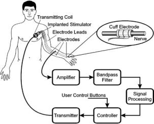
The use of cutaneous afferent feedback in correction of drop-foot has to date been evaluated in several patients. The first evaluation included a 35 year-old subject with a hemiplegic dropfoot. In this case, the cuff electrode was connected to the control system through percutaneous wires, and an external stimulator was placed over the Tibialis Anterior muscle (84). A later version of the system was tested in a 32-year old subject, and the external stimulator was here replaced with an implanted cuff electrode around the peroneal nerve, which innervates the tibialis anterior muscle. An implantable system is currently under development and clinical testing by the Danish company Neurodan A/S.
Cutaneous Afferent Feedback for the Restoration of Hand Grasp. The fingers of the human hand contain an estimated 200–300 touch sensing receptors per square centimeters within the skin. It is among the highest densities of sensory receptors in the body (85). The cutaneous receptors and their responses have been studied extensively using microneurography techniques in normal subjects (85–87). The sensors mainly signal information about indentation and stretch of the skin, and the sensors play an important role in the control of precise finger movements and hand grasp while manipulating objects. It was found that slips across the skin were shown to elicit automatic motor reflex responses that increased the grasp force.
A FES system was developed to evaluate the use of cutaneous sensory information in restoration of hand grasp functions. The system has been evaluated in three spinal cord injured subjects (88–92). Results from a 27 years-old tetraplegic male with a complete C5 spinal cord injury (2 years postinjury) are presented in detail here. Before system was implanted, the patient had no voluntary elbow extension, no wrist function, and no finger function. Furthermore, he had only partial sensation in the thumb, but no sensation in 2nd to 5th fingers. He was implanted with a tripolar nerve cuff electrode on the palmar interdigital nerve (branching of the median nerve). Eight intramuscular stimulation wire electrodes were simultaneously placed in the following muscles: Extensor Pollicis Brevis, Flexor Pollicis Brevis, Adductor Pollicis, and Flexor Digitorum Longus to provide the grip control.
The cuff electrode was implanted around the palmar interdigital nerve, which is a pure cutaneous nerve innervating the radial aspect of the index finger (branching off the median nerve). The cuff electrode recordings were used to detect the occurrence of fast slips (increased neural activity was recorded when objects were slipping through the subject’s fingers, and the neural activity showed similar characteristics as the cutaneous sural nerve activity shown in Fig. 26).
The stimulator was controlled by a computer, which also sampled the nerve signals and performed the signal analysis. When stimulation was turned on, the object could be held in a lateral grasp (key grip) by the stimulated thumb. If the object slipped, either because of decreasing muscle force or increasing load, the computer detected this from the processed nerve signal and increased the stimulation intensity with a fixed amount so that the slip was arrested, and the object again held in a firm grip. When extra weight was added, the slipped distance was also comparable to the performance of healthy subjects.
ELECTRONEUROGRAPHY 127
Today this system is developed to an extent where the subject can use it during functional tasks. During an eating session where the subject has a fork in his instrumented hand (grasped between the thumb and index finger), the control system is designed to decrease the stimulation of the finger muscles until the feedback signal from the skin sensors detects a slip between the index finger and the fork. When a slip is detected, the stimulation to the thumb increases automatically proportional to the strength of the sensory feedback, and if no further slips are detected, the controller starts to decrease the stimulation. This continuous tracking of the minimally necessarily needed stimulation means that the hand muscles are only loosely stimulated when the subject decides to rest his arm (which typically happens when they have a conversation with one or more of the persons at a dinner table). The stimulation will automatically increase when they start to eat again by placing the fork in the food. A typically eating session will last 20–30 min. A large fraction of this time is dedicated to ‘‘noneating’’ activities. During such times, the stimulation is at a minimum (keeping the fork in the hand with a loose grasp) and thereby preventing the hand muscles to be fatigued. When the feedback is taken away, the subject will typically leave the stimulation on at high stimulation intensity for the full eating session. This will fatigue the stimulated muscles, and the subject will try to eat their dinner faster, or they will rest their muscles at intervals by manually decreasing the stimulation. It is an effort that requires more attention from the subject than the automatic adjustment of the stimulation intensity.
The natural sensory feedback system was developed at Aalborg University, Denmark, and based on a telemetric system and on the Freehand system (NeuroControl Corp.). The Freehand system consists of a number of epimysial stimulation electrodes to provide muscle activation. More than 200 patients have to date received this system (Fig. 27).
Figure 27. A neural prosthetic system for lateral-key grip restoration after spinal cord injury including sensory feedback. The FreeHand stimulation system (developed at Case Western Reserve University, Ohio) was modified to take advantage of natural sensory feedback signals obtained from a cutaneous, digital nerve in the hand. (Adapted from Ref. 92 with permission.)
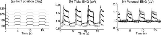
128 ELECTRONEUROGRAPHY
Experimental Neural Prosthetic Systems
Somatic Afferent Feedback in Control of Joint Movement.
The natural sensors that carry information about movement and orientation of the body in space (proprioception) are primarily located in the muscles, tendons, joints, and ligaments. The sensory signals are essential for the central nervous system in voluntary control of movement. In contrast to the more on–off type of information provided by the natural sensors located in the skin (e.g., heel contract and toe off events as used in correction of drop foot), the muscle spindle afferents are believed to carry information on muscle displacement (length, velocity, and acceleration). The proprioceptive sensors may therefore be useful in FES systems for control of joint movement. A majority of the research within this area has so far focused on restoration of standing and walking after spinal cord injury, however, the same principles explained here may be applied in control of upper extremity joints. Muscle afferent signals have been studied in animal models using intrafascicular (6,93) and whole nerve cuff electrodes (94,95), and these studies have revealed some characteristic features in muscle afferent responses that must be taken into consideration in a future FES system design.
Muscle afferent signals were obtained from passively stretched agonist-antagonist muscle groups around the ankle joint innervated by the tibial and the peroneal nerve branches in an animal model of spinal cord injury (6,94). The muscle afferent signals were recorded during simple flexion-extension rotations of the ankle joint, and it was found that the muscle afferent activity from the two nerves responded in a complementary manner, see Fig. 28. Thus, the muscle afferent activity increased during muscle stretch, but the activity stopped as soon as the movement was reversed, and the muscle was shortened. In the animal models used here, the muscles are not under normal efferent control from the central nervous system, and the intrafusal muscle fibers (where the muscle spindles are located) therefore become slack during muscle shortening, and the muscle spindles stop responding. The muscle afferents can therefore only provide information about muscle length during muscle stretch. In order to obtain a continuous and reliable muscle afferent feedback signal, it is necessary to use information from more muscles or muscle groups acting around a joint.
In spite of the nonlinear nature of the muscle afferent signals, it has shown to be possible to use the signals as feedback in a closed-loop control system. Yoshida and Horch (6) obtained control of ankle extension (ramp-and- hold movement) against a load and ankle flexion-extension (sinosoidal movement) in a cat model. A look-up table was first established by creating a map between the neural activity and the ankle joint angle. The tibial and peroneal nerve activity was simultaneously recorded using intrafascicular electrodes and decoded according to the look-up table.
To better incorporate the nonlinear behavior, more sophisticated information extraction algorithms have been employed to decode the muscle afferent signals, including a Neuro-Fuzzy network (96), and neural networks (97,98). In all cases, continuous information from both an agonist and antagonist muscle group was used as input to the networks.
The next step is to explore if muscle afferent signals on selected peripheral nerves can be recorded in humans and applied to improve FES standing.
Visceral Neural Signals in Control of Bladder Function.
Normal bladder function (storage and emptying of urine) is dependent on mechanoreceptive sensors detecting bladder volume and efferent control that trigger a bladder contraction. Normal bladder function can be affected by a number of pathological diseases or neural injuries, for example when spinal cord injury occurs at the thoracic or cervial level, the neural pathways normally controlling the bladder are affected. Bladder dysfunction can result in an either overactive bladder (small volume capacity and incomplete emptying, referred to as neurogenic detrusor overactivity) or an underactive bladder (high volume capacity), however, the result of both states is incontinence. Neurogenic detrusor overactivity is the most common form of detrusor dysfunction following spinal cord injury. An overfilling of the bladder can also lead to a possible lifethreatening condition of autonomic dysreflexia (overactivity of the autonomic nervous system).
Conventional treatments include suppression of reflex contraction by drugs, manual catheterization, or inhibition of the reflex contraction by surgical intervention, which is also referred to as dorsal rhizotomy. Dorsal rhizotomy
Figure 28. Muscle afferent signals recorded from the Tibial and Peroneal nerve branches during passive joint rotation in a rabbit model. The Tibial and Peroneal nerve activity modulated in a push– pull manner (i.e. the nerves responded to muscle stretch of the Gastrocnemius/Soleus and the Tibialis Anterior muscles, respectively). The magnitude of the response modulated with the initial position of the joint (the amount of prestretch in the muscles). (Courtesy of Dr. Jensen, Aalborg University.)
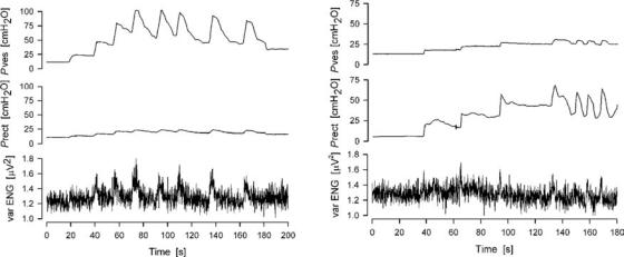
ELECTRONEUROGRAPHY 129
Figure 29. Two examples of recorded neural activity from the sacral roots in an anaesthetized human subject in preparation for surgery for implantation of a FineTech-Brindley Bladder system. The traces show the bladder pressure (top), rectal pressure (middle) and extradural sacral root activity (bottom) over time. (Courtesy of M. Kurstjens.)
increases the bladder capacity, however, reflex erection in male patients is lost, and this is in most cases not an attractive solution. To reestablish continence a closed-loop FES system has been suggested including sensory feedback on bladder volume and/or detrusor activation from bladder nerves.
Work in anaesthetized cats showed correlation between recorded activity from the S2 sacral root and the intravesical pressure associated with fullness of the bladder. Recently, similar information on bladder volume information has also been demonstrated in nerve cuff recordings from the S3 sacral root and the pelvic nerve in anaesthetized pigs (99) and extradural cuff recordings from sacral roots in humans (100) (see Fig. 29). The findings reveal, however, some problems in finding a reliable sensory feedback signal. It proved difficult to detect slow increases in bladder volume (99). Further, recordings from the pelvic nerve or sacral roots, however, are frequently contaminated with activity from other afferents, such as cutaneous and muscle afferents from the pelvic floor, rectum, and anus (100).
A closed-loop FES system for the management of neurogenic detrusor activity would work by using the sensory information from the bladder nerves to inhibit detrusor contractions by stimulating pudendal or penile nerves, or block efferent or afferent pelvic nerve transmission to prevent reflex detrusor contractions. The principle was tested in an anesthetized cat prepration where nerve cuff recordings from the S1 in cats could detect bladder hyperreflexive like contractions. However, the contractions were detected with a time delay in the order of seconds (using a CUMSUM alogrithm), which decreases the feasibility of the system (101).
Visceral Neural Signals in Respiratory Control. Obstructive sleep apnea is characterized by occlusions of upper airways during sleep. Electrical stimulation of the genioglossus muscle directly or via the hypoglossal nerve can
improve the obstructions, however, a signal for detecting the occurrence of the obstructions will be useful in a FES closed-loop application (102).
This principle has been tested in a closed-loop FES system where the response of hypoglossal nerve was recorded during external loading of the pharynx during sleep to simulate upper airway obstructions in a dog model. It was shown that the hypoglossal nerve activity modulated with the pressure both during REM and NREM sleep. Any change in the cyclical rhythm of the recorded activity was used as an indication of the onset of apnea to the controller and triggered the onset of the stimulation of the same hypoglossal nerve to prevent the airway obstruction (103). Stimulation and recording from the same nerve is feasible in this case because the only information needed from the hypoglossal nerve is an indication of the onset of airway obstruction (i.e., no continuous information is needed).
CONCLUSIONS
The goal of the article is to provide the reader with an overview of currently available neural electrodes for longterm interfacing peripheral neural tissue. This is done to evaluate their suitability to monitor the neural traffic in peripheral nerves and their suitability to perform as sensors in neural prosthetic devices.
The role of neural prosthetic systems for increasing the quality of life of disabled individuals is becoming more evident each day. As the demand to develop systems capable of providing expanded functionality increases, so too does the need to develop adequate sensors for control. The use of natural sensors represents an innovation. Future research will show whether nerve-cuff electrodes and other types of peripheral nerve electrodes can be used to reliably extract signals from the large number of other receptors in the body to improve and expand on the use of natural sensors in neural prosthetic systems.
130 ELECTRONEUROGRAPHY
ACKNOWLEDGMENTS
The authors gratefully acknowledge The Danish National Research Foundation and The Danish Research Councils for their financial support.
BIBLIOGRAPHY
Cited References
1.Hoffer JA. Techniques to study spinal-cord, peripheral nerve and muscle activity in freely moving animals. In Boulton AA, Baker GB, Vanderwolf CH, editors. Neural Prostheses. Replacing Motor Function After Disease or Disability. New York Oxford: Oxford University Press; 2005.
2.Branner A, et al. Long-term stimulation and recording with a penetrating microelectrode array in cat sciatic nerve. IEEE Trans Biomed Eng 2004;51(1):146–157.
3.Lee DH, Claussen GC, Oh S. Clinical nerve conduction and needle electromyography studies. J Am Acad Orthop Surg 2004 July–Aug; 12(4):276–287. Review.
4.Fuller G. How to get the most out of nerve conduction studies and electromyography. J Neurol Neurosurg Psychiatry. 2005; 76(Suppl. 2):ii41–46. Review.
5.Crago PE, Nakai RJ, Chizeck HJ. Feedback regulation of hand grasp opening and contact force during stimulation of paralyzed muscle. IEEE Trans Biomed Eng 1991;38(1): 17–28.
6.Yoshida K, Horch K. Closed-loop control of ankle position using muscle afferent feedback with functional neuromuscular stimulation. IEEE Trans Biomed Eng 1996;43(2):167–176.
7.Haugland M, Hoffer JA. Slip Information Provided by Nerve Cuff Signals: Application in Closed-Loop Control of Functional Electrical Stimulation. IEEE Trans Rehab Eng 1994;2:29–36.
8.Sinkjaer T, Haugland M, Haase J. Natural neural sensing and artificial muscle control in man. Exp Brain Res 1994;98(3):542–545.
9.Sinkjær T, Haugland M, Struijk J, Riso R. Long-term cuff electrode recordings from peripheral nerves in animals and humans. In: Windhorst U, Johansson H, editors. Modern Techniques in Neuroscience. New York: Springer; 1999. p 787–802.
10.Stein RB, et al. Encoding mechanisms for sensory neurons studied with a multielectrode array in the dorsal root ganglion. Can J Physiol Phramacol 2004;82:757–768.
11.Stein RB, et al. Coding of position by simultaneously recorded sensory neurones in the cat dorsal root ganglion. J Physiol 2004;560(3):883–896.
12.Hansen M, Haugland M, Sinkjær T. Evaluating Robustness of gait event detection based on machine learning and natural sensors. IEEE Trans Neural Syst Rehab Eng 2004;12: 1:81–87.
13.Hoffer JA, Kallesoe K. Nerve cuffs for nerve repair and regeneration. Prog Brain Res 2000;128:121–134.
14.Struijk JJ, Thomsen M, Larsen JO, Sinkjaer T. Cuff electrodes for long-term recording of natural sensory information. IEEE Eng Med Biol Mag 1999;18(3):91–98.
15.Haugland M, Sinkjær T. 2000.
16.Riso RR. Perspectives on the role of natural sensors for cognitive feedback in neuromotor prostheses. Automedica 1998;16:329–353.
17.McDonnall D, Clark GA, Normann RA. Selective motor unit recruitment via intrafascicular multielectrode stimulation. Can J Physiol Pharmacol 2004;82(8–9):599–609.
18.McDonnall D, Clark GA, Normann . Interleaved, multisite electrical stimulation of cat sciatic nerve produces fatigueresistant, ripple-free motor responses. IEEE Trans Neural Syst Rehabil Eng 2004;12(2):208–215.
19.Aoyagi Y, et al. Capabilities of a penetrating microelectrode array for recording single units in dorsal root ganglia of the cat. J Neurosci Methods 2003;30: 128(1–2):9–20
20.Webster. 1998.
21.Hodgkin AL, Huxley AF. A quantitative description of membrane current and its application to conduction and excitation in nerve. J Physiol (London) 1952;117:500–544.
22.Chiu SY, Ritchie JM, Rogart RB, Stagg D. A quantitative description of membrane currents in rabbit myelinated nerve. J Physiol 1979;292:149–166.
23.Sweeney JD, Mortimer JT, Durand D. Modeling of mammalian myelinated nerve for functional neuromuscular stimulation. Proceedings of the 9th Annual International Conference of the IEEE EMBS 1987; 1577–1578.
24.Varghese A. Membrane Models. In: Bronzino JD, editor. The Biomedical Engineering Handbook: 2nd ed. Boca Raton (FL): CRC Press LLC; 2000.
25.McIntyre CC, Richardson AG, Grill WM. Modeling the excitability of mammalian nerve fibers: influence of afterpotentials on the recovery cycle. J Neurophysiol 2002;87(2):995–1006.
26.Struijk JJ. The extracellular potential of a myelinated nerve fiber in an unbounded medium and in nerve cuff models. Biophys J 1997;72:2457–2469.
27.Perez-Orive , Durand . Modeling study of peripheral nerve recording selectivity. IEEE Trans Rehabil Eng 2000;8(3):320– 329.
28.Taylor J, Donaldson N, Winter J. Multiple-electrode nerve cuffs for low-velocity and velocity-selective neural recording. Med Biol Eng Comput 2004;42(5):634–643.
29.Chemineau ET, Schnabel V, Yoshida K. A modeling study of the recording selectivity of longitudinal intrafascicular electrodes. In: Wood D, Taylor J, editors. Getting FES into clinical practice. Proceedings of IFESS-FESnet 2004, 9th Annual Conference of the International Functional Electrical Stimulation Society and the 2nd Conference of FESnet 6–9 September, 2004Bournemouth, UK. 2004 p 378–380.
30.Yoshida K, Struijk JJ. The theory of peripheral nerve recording. In: Horch KW, Dhillon GS, editors. Neuroprosthetics: Theory and Practice World Scientific Publishing Co.; 2004.
31.Nikolic ZM, Popovic DB, Stein RB, Kenwell Z. Instrumentation for ENG and EMG recordings in FES systems. IEEE Trans Biomed Eng 1994;41(7):703–706.
32.Stein RB, et al. Stable long-term recordings from cat peripheral nerves. Brain Res 1977;128(1):21–38.
33.Yoshida K, Stein RB. Characterization of signals and noise rejection with bipolar longitudinal intrafascicular electrodes. IEEE Trans Biomed Eng 1999;46(2):226–234.
34.Ott HW. Noise Reduction Techniques in Electronic Systems. 2nd ed, New York: John Wiley & Sons, Inc.; 1988.
35.Grimnes S, Martinsen ø G. Bioimpedance and Bioelectricity Basics. London: Academic Press; 2000 p 221.
36.Heiduschka P, Thanos S. Implantable Bioelectronic Interfaces for Lost Nerve Functions. Prog Neurobiol 1998;55:433– 461.
37.Mannard A, Stein RB, Charles D. Regeneration electrode units: implants for recording from single peripheral nerve fibers in freely moving animals. Science 1974;183(124):547– 549.
38.Stieglitz T, et al. A biohybrid system to interface peripheral nerves after traumatic lesions: design of a high channel sieve electrode. Biosensors Bioelectronics 2002;17: 685–696.
39.Edell DJ. A peripheral nerve information transducer for amputees: long-term multichannel recordings from rabbit peripheral nerves. IEEE Trans Biomed Eng 1986;33(2):203– 214.
40.Akin T, Najafi K, Smoke RH, Bradley RM. A micromachined silicon sieve electrode for nerve regeneration studies. IEEE Trans Biomed Eng 1994;41:305–313.
41.Bradley RM, Smoke RH, Akin T, Najafi K. Functional regeneration of glossopharyngeal nerve through michromachined
sieve electrode arrays. Brain Res 1992;594:84–90.
´
42. Lago N, Ceballos D, RodrUguez FJ, Stieglitz T, Navarro X. Long-term assessment of axonal regeneration through polyimide regnerative electrodes to interface the peripheral nerve. Biomaterials 2005;26:2021–2031.
43. Kovacs GTA, et al. Silicon-substrate microelectrode arrays for parallel recording of neural activity in peripheral and cranial nerves. IEEE Trans Biomed Eng 1994;41(6):567– 577.
44. Zhao Q, Dahlin LB, Kanje M, Lundborg G. Specificity of muscle reinnervation following repair of the transected sciatic nerve. A comparative study of different repair techniques in the rat. J Hand Surg 1992;17:257–261.
45. Yoshida K, Riso R. Peripheral nerve recording electrodes and techniques. In Horch K, Dhillon GS, editors. Neuroprosthetics. Theory and Practice. 1st ed. New York: World Scientific; 2004. p 683–744.
46. Bradley RM, Cao X, Akin T, Najafi K. Long term chronic recordings from peripheral sensory fibers using a sieve electrode array. J Neurosc Methods 1997;73:177–186.
47. Mesinger AF, et al. Chronic recording of regenerating VIIIth nerve axons with a sieve electrode. J Neurophysiol 2000;83:611–615.
48. Shimantani Y, Nikles SA, Najafi K, Bradley RM. Long-term recordings from afferent taste fibers. Physiol Beh 2003;80: 309–315.
49. Berthold CH, Lugnegard H, Rydmark M. Ultrastructural morphometric studies on regeneration of the lateral sural cutaneous nerve in the white rat after transection of the sciatic nerve. Scan J Plast Reconstr Surg Supp l 1985;30:1–126.
˚
50. Vallbo A, Hagbart KE. Activity from skin mechanoreceptors ecorded percutaneously in awake human subjects. Exper Neurol 1968;21:270–289.
˚
51. Vallbo A, Hagbart KE, Wallin BG. Microneurography: how the technique developed and its role in the investigation of the sympathetic nervous system. J Appl Physiol 2004;96: 1262–1269.
52. Hallin RG, Wiesenfeld-Hallin Z, Duranti R. Percutaneous microneurography in man does not cause pressure block of almost all axons in the impaled nerve fascicle. Neurosc Lett 1986;68:356–361.
53. Bowmann BR, Erickson RC. Acute and chronic implanation of coiled wire intraneural electrodes during cyclical electrical stimulation. Ann Biomed Eng 1985;13:75–93.
54. Malagodi MS, Horch K, Schoenberg A. An intrafascicular electrode for recording action potentials in peripheral nerves. Ann Biomed Eng 1989;17:397–410.
55. McNaughton TG, Horch K. Metalized polymer fibers as leadwires and intrafacicular microelectrodes. J Neurosc Methods 1996;8:391–397.
56. Gonzalez C, Rodriguez M. A flexible perforated microelectrode arry probe for action potential recording in nerve and muscle tissue. J Neurosc Methods 1997;72:189–195.
57. Lefurge T, et al. Chronically implanted intrafascicular recording electrodes. Ann Biomed Eng 1991;19:197– 207.
58.Malmstrom M, McNaughton TG, Horch K. Recording properties and biocompatibility of chronically implanted polymer-
ELECTRONEUROGRAPHY 131
based intrafascicular electrodes. Ann Biomed Eng 1998;26: 1055–1064.
59.(a) Jones KE, Campebll PK, Normann RA. A Glass/Silicon Composite Intracortical Electrode Array. Ann Biomed Eng 1992;20:423–437. (b) Lawrence SM, et al. Long-term biocompatibility of implanted polymer-based intrafascicular electrodes. J Biomed Mater Res 2002; 63(5):501–506.
60.Rousche PJ, Normann RA. A method for pneumatically inserting an array of penetrating electrodes into cortical tissue. Ann Biomed Eng 1992;20:413–422.
61.Branner A, Normann RA. A multielectrode array for intrafasciclar recording and stimulation in sciatic nerve of cats. Brain Res Bull 1999;51(4):293–306.
62.Branner A, Stein RB, Normann RA. Selective Stimulation of Cat Sciatic Nerve Using an Array of VaryingLength Microelectrodes. J Neurophysiol 2001;85:1585– 1594.
63.Gasson MN, et al. Bi-directional human machine interface via direct neural connection. Proceedings of the IEEE Conference on Robot and Human Interactive Communication, Berlin, Germany; 2002, p 26–270.
64.Stein RB, et al. Principles underlying new methods for chronic neural recording. Can J Neurol Sci 1975;2(3):235– 244.
65.Haugland M. A flexible method for fabrication of nerve cuff electrodes. In: Proceedings of the 18th Annual Conference IEEE Engineering in Medicine and Biology. Amsterdam The Netherlands: 1996p 964–965.
66.Stieglitz T, Meyer JU. Implantable microsystems: polyimidebased neuroprostheses for interfacing nerves. Med Device Technol 1999;10(6):28–30.
67.Rodriguez FJ, et al. Polyimide cuff electrodes for peripheral nerve stimulation. J Neurosci Methods 2000;98(2):105– 118.
68.Veraat C, Grill WM, Mortimer JT. Selective control of muscle activation with a multipolar nerve cuff electrode. IEEE Trans Biomed Eng 1993;40:640–653.
69.Schuettler M, Stieglitz T. 18 polar hybrid cuff electrodes for stimulation of peripheral nerves. Proceedings of the IFESS. Aalborg, Denmark: 2000. p 265–268.
70.Kallesoe K, Hoffer JA, Strange K, Valenzuela I. Simon Fraser University, Implantable cuff having improved closure. US patent 5,487,756, 1994.
71.Naples GG, Mortimer JT, Schiner A, Sweeney JD. A spiral nerve cuff electrode for peripheral nerve stimulation. IEEE Trans Biomed Eng 1988;35(11):905–916.
72.Grill WM, et al. Thin film implantable electrode and method of manufacture. Case Western Reserve University, US patent 5,324,322. 1994 June 28.
73.Grill WM, Tarler MD, Mortimer JT. Case western Reserve University. Implantable helical spiral cuff electrode. US patent 5,505,201. 1996 April 9.
74.Hoffer JA, Marks WB, Rymer Z. Nerve fiber activity during normal movements. Soc Neurosc Abs 1974: 258.
75.Stein RB, et al. Impedance properties of metal electrodes for chronic recording from mammalian nerves. IEEE Trans Biomed Eng 1978;25:532–537.
76.Tyler DJ, Durand DD. A slowly penetrating interfascicular nerve electrode for selective activation of peripheral nerves. IEEE Trans Rehab Eng 1997;5(1):51–61.
77.Tyler DJ, Durand DD. Functionally Selective Peripheral Nerve Stimulation With a Flat Interface Nerve Electrode. IEEE Trans Neural Syst Rehabil Eng 2002;10(4):294– 303.
78.Yoo PB, Sahin M, Durand DD. Selective stimulation of the canine hypoglossal nerve using a multi-contact cuff electrode. Ann Biomed Eng 2004;32(4):511–519.