

- •VOLUME 3
- •CONTRIBUTOR LIST
- •PREFACE
- •LIST OF ARTICLES
- •ABBREVIATIONS AND ACRONYMS
- •CONVERSION FACTORS AND UNIT SYMBOLS
- •EDUCATION, COMPUTERS IN.
- •ELECTROANALGESIA, SYSTEMIC
- •ELECTROCARDIOGRAPHY, COMPUTERS IN
- •ELECTROCONVULSIVE THERAPHY
- •ELECTRODES.
- •ELECTROENCEPHALOGRAPHY
- •ELECTROGASTROGRAM
- •ELECTROMAGNETIC FLOWMETER.
- •ELECTROMYOGRAPHY
- •ELECTRON MICROSCOPY.
- •ELECTRONEUROGRAPHY
- •ELECTROPHORESIS
- •ELECTROPHYSIOLOGY
- •ELECTRORETINOGRAPHY
- •ELECTROSHOCK THERAPY.
- •ELECTROSTIMULATION OF SPINAL CORD.
- •ELECTROSURGICAL UNIT (ESU)
- •EMERGENCY MEDICAL CARE.
- •ENDOSCOPES
- •ENGINEERED TISSUE
- •ENVIRONMENTAL CONTROL
- •EQUIPMENT ACQUISITION
- •EQUIPMENT MAINTENANCE, BIOMEDICAL
- •ERGONOMICS.
- •ESOPHAGEAL MANOMETRY
- •EVENT-RELATED POTENTIALS.
- •EVOKED POTENTIALS
- •EXERCISE FITNESS, BIOMECHANICS OF.
- •EXERCISE, THERAPEUTIC.
- •EXERCISE STRESS TESTING
- •EYE MOVEMENT, MEASUREMENT TECHNIQUES FOR
- •FETAL MONITORING
- •FETAL SURGERY.
- •FEVER THERAPY.
- •FIBER OPTICS IN MEDICINE
- •FICK TECHNIQUE.
- •FITNESS TECHNOLOGY.
- •FIXATION OF ORTHOPEDIC PROSTHESES.
- •FLAME ATOMIC EMISSON SPECTROMETRY AND ATOMIC ABSORPTION SPECTROMETRY
- •FLAME PHOTOMETRY.
- •FLOWMETERS
- •FLOWMETERS, RESPIRATORY.
- •FLUORESCENCE MEASUREMENTS
- •FLUORESCENCE MICROSCOPY.
- •FLUORESCENCE SPECTROSCOPY.
- •FLUORIMETRY.
- •FRACTURE, ELECTRICAL TREATMENT OF.
- •FUNCTIONAL ELECTRICAL STIMULATION
- •GAMMA CAMERA.
- •GAMMA KNIFE
- •GAS AND VACUUM SYSTEMS, CENTRALLY PIPED MEDICAL
- •GAS EXCHANGE.
- •GASTROINTESTINAL HEMORRHAGE
- •GEL FILTRATION CHROMATOGRAPHY.
- •GLUCOSE SENSORS
- •HBO THERAPY.
- •HEARING IMPAIRMENT.
- •HEART RATE, FETAL, MONITORING OF.
- •HEART VALVE PROSTHESES
- •HEART VALVE PROSTHESES, IN VITRO FLOW DYNAMICS OF
- •HEART VALVES, PROSTHETIC
- •HEART VIBRATION.
- •HEART, ARTIFICIAL
- •HEART–LUNG MACHINES
- •HEAT AND COLD, THERAPEUTIC
- •HEAVY ION RADIOTHERAPY.
- •HEMODYNAMICS
- •HEMODYNAMIC MONITORING.
- •HIGH FREQUENCY VENTILATION
- •HIP JOINTS, ARTIFICIAL
- •HIP REPLACEMENT, TOTAL.
- •HOLTER MONITORING.
- •HOME HEALTH CARE DEVICES
- •HOSPITAL SAFETY PROGRAM.
- •HUMAN FACTORS IN MEDICAL DEVICES
- •HUMAN SPINE, BIOMECHANICS OF

F
FES. See FUNCTIONAL ELECTRICAL STIMULATION.
FETAL MONITORING
MICHAEL R. NEUMAN
Michigan Technological
University
Houghton, Michigan
INTRODUCTION
Fetal monitoring is a special type of electronic patient monitoring aimed at obtaining a record of vital physiologic functions during pregnancy and birth. Such monitoring is applied in assessing the progress of pregnancy and labor, and it can identify conditions that concern the clinician caring for the patient. These nonreassuring recordings can lead to special considerations in caring for the pregnant patient and in managing her labor. Although these recordings are no longer considered to be definitive in identifying most forms of fetal distress, they can help to reassure patient and clinician that the fetus is able to withstand the physiologicstressoflabor and delivery. The technologyisalso useful in assessing high risk pregnancies, which, in most cases, is only reassuring as opposed to giving a definitive diagnosis. Although this technology is now recognized to have diagnostic limitations, it is still frequently used in the hospital and clinics as an adjunct to other diagnostic evaluations.
PHYSIOLOGIC VARIABLES MONITORED
The goal of fetal monitoring is to ensure that vital fetus organs receive adequate perfusion and oxygen so that metabolic processes can proceed without compromise and these organs can carry out their functions. Thus, an ideal situation for monitoring from the physiologic standpoint would be to monitor the perfusion and oxygen tension in the fetal central nervous system, heart, kidneys, and brain, with the brain being by far the most important. It is also important to know that the fetus is receiving adequate oxygen and nutrients from the mother through the placenta. Unfortunately, it is not possible to directly or even indirectly measure these variables in the fetus in utero using currently available technology. One, therefore, must look for related secondary variables that are practical for monitoring and are related to these critical variables. In the following paragraphs, some of these variables and the methods used to obtain them are described.
METHODS OF MONITORING BY A HUMAN OBSERVER
Any discussion of fetal monitoring must begin by pointing out an obvious, but often overlooked, fact that fetal mon-
itoring does not always require expensive electronic equipment. Basic fetal monitoring can be carried out by a trained clinician using his or her hands, ears, and brain. A fetoscope is a stethoscope especially designed for listening to the fetal heart sounds through the maternal abdomen, which can be used to follow the fetal heart rate (FHR), and a hand placed on the abdomen over the uterus can be used to detect the relative strength, frequency, and duration of uterine contractions during the third trimester of pregnancy and labor. Any woman who has experienced labor will point out that the patient is also able to detect the occurrence of uterine contractions during labor. Although these techniques are only qualitative, they can be quite effective in providing information on the patient in labor and frequently represent the only fetal monitoring that is necessary in following a patient.
The main problems with this type of fetal monitoring are associated with convenience, fatigue, data storage and retrieval, and the difficulty of simultaneously processing multiple inputs. Electronic instrumentation can help to overcome these types of problems. Although electronic devices are less flexible and, at the present time, unable to interpret data as well as their human counterparts, the electronic devices can provide quantitative data, continuously monitor patients with minimal interruption of hospital routines, monitor for extended periods of time without fatigue, store data in forms that can be reevaluated at a later time, and, in some circumstances, make elementary logical decisions and calculations based on the data. Thus, the electronic monitor can serve as an extension of the clinician’s data-gathering senses and provide a convenient method of recording and summarizing these data. Such a monitoring apparatus has the potential of allowing the clinician to optimize his or her limited available time.
FETAL HEART RATE MONITORING
The widespread use of electronic fetal monitoring was the result of the development of a practical method of sensing the fetal electrocardiogram and determining the instantaneous fetal heart rate from it. Much of the early work in this area was carried out by Dr. Edward Hon and associates who demonstrated a practical technique for directly obtaining the fetal electrocardiogram during labor (1). Techniques for obtaining the fetal heart rate can be classified as direct or indirect. The former involves invasive procedures in which a sensor must come into contact with the fetus to pick up the fetal electrocardiogram; the latter techniques are relatively noninvasive procedures where the mother’s body serves as an intermediary between the fetus and the electronic instrumentation. In this case, the maternal tissue conducts a signal (electrical or mechanical) between the fetus and the surface of the mother’s abdomen.
287
288 FETAL MONITORING
Direct Determination of Fetal Heart Rate
Direct FHR determinations are made from the fetal electrocardiogram (FECG). This signal is obtained by placing an electrode on the fetus and a second electrode in the maternal vaginal fluids as a reference point. These electrodes are connected to a high input impedance, high common-mode rejection ratio bioelectric amplifier. Such a direct connection to the fetus can be made only when the mother is committed to labor, the uterine cervix has dilated at least 2 cm, and the chorioamniotic membranes have been ruptured. In principle, it is possible to pass a wire through the maternal abdominal wall into the uterine cavity and beneath the fetal skin to obtain the FECG, and this technique was experimentally reported in the past (2). The method, however, places the mother and fetus at risk and is not used or suitable for routine clinical application. Indirect methods of determining the FHR that are available today make the application of such a technique unnecessary. Thus, the method that is directly used to obtain the FECG is to attach an electrode to the fetal presenting part through the cervix once the mother is committed to labor and the fetal membranes can be ruptured.
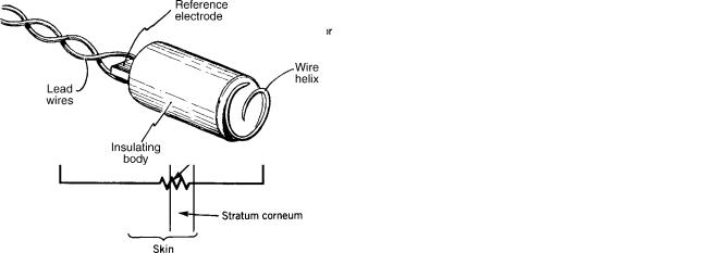
Although many different types of electrodes for obtaining the FECG have been described, best results are obtained when the electrode actually penetrates the fetal skin. The reason is illustrated in Fig. 1. The fetus lines in a bath of a amniotic fluid that is electrically conductive due to its electrolyte content. This amniotic fluid tends to short-out the fetal electrocardiogram on the skin surface, therefore, those potentials that are seen on the surface are relatively weak and affected by noise. Even if it were physically possible to place conventional chest electrodes on the fetus for picking up the electrocardiogram, a poor-quality signal would be obtained because of this shunting effect. The amniotic fluid does, however, provide a good central terminal voltage for the fetal electrocardiogram because it contacts most of the fetal body surface.
The fetal head is normally positioned against the dilating cervix when the mother is in labor, but it is possible for the fetal buttocks or other parts to present first. As the cervix dilates, the skin on the presenting part can be observed through the vagina, and it is possible to place an electrode on or within this skin. If this electrode penetrates the fetal scalp (or other exposed skin surface), it contacts the subcutaneous tissue. As an electrical resistance associated with the surface layers of the fetal skin exists, as indicated in Fig. 1, placing the electrode subcutaneously bypasses this resistance and gives a stronger, more reilable signal. Penetrating the skin also helps to physically keep the electrode in place on the fetus during movement associated with labor.
Various types of penetrating fetal electrodes ranging from fish hooks (3) to wound chips (4) have been developed over the years. Today, the most frequently applied electrode in the helical electrode originally described by Hon et al. (5). This electrode, as illustrated in Fig. 2, consists of a section of a helix of stainless-steel wire on an electrically insulating support. The tip of the wire is sharpened to a point that can penetrate the fetal skin when pressed against it and rotated to advance the helix. Typical dimensions of the wire helix are 5 mm in diameter with 1.25 turn of the wire exposed so that the tip of the helix is 2 mm from the surface of the insulator. A second stainless-steel electrode consisting of a metal strip is located on the opposite end of the insulator from the helix and is used to establish contact with the amniotic fluid through the fluid in the vagina. Lead wires connect the two electrodes to the external monitor.
The electrode is attached to the fetal presenting part by means of a special applicator device, which allows the electrode helix to be pressed against the fetal head to penetrate the skin and be twisted so that the entire wire is advanced beneath the surface of the skin until the insulating portion of the electrode contacts the skin. The flexible lead wires then exit through the vagina and can be connected to the monitoring electronics.
Signal Processing
In fetal heart monitoring, it is desired to have a continuous recording of the instantaneous heart rate. A fetal monitor must, therefore, process the electrocardiogram sensed by
Figure 1. Schematic view and equivalent circuit of a direct fetal |
Figure 2. A helical direct fetal ECG scalp electrode of the type |
ECG electrode penetrating the fetal skin. |
described by Hon et al. (5). |
FETAL MONITORING |
289 |
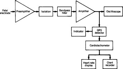
the electrode and present the results on a computer monitor or paper printout. A typical electronic system for doing this recording is illustrated in Fig. 3. The signal from the fetal electrode has an amplitude ranging from 50 mV to 1.2 mV, which is amplified to a more suitable level for processing by an amplifier stage. The input of this aimplifier is electrically isolated and must have a very high input impedance and low lekage current because of the polarizable nature of most fetal electrodes. A high common-mode rejection ratio is also important, because a relatively strong maternal electrocardiogram signal is present on both electrodes. Another characteristic of the amplifier system is that it includes filtering to minimize the amplification of noise and motion artifact from the fetal electrode. As the purpose of the electronics is primarily to display the instantaneous heart rate, the filtering can distort the configuration of the fetal electrocardiogram as long as it does not affect the time at which the QRS complex appears, as it is used to determine the heart rate. For this reason, a relatively narrow band-pass filter is often used. The QRS complex contains higher frequencies than the rest of the electrocardiogram, and noise frequently has a predominance of the lower frequencies. For this reason, the bandpass filter can be centered at frequencies as high as 40 Hz.
Many ways exist for the QRS complex can be detected. The simplest of these is a threshold detector that indicates whenever the output voltage from the amplifier exceeds a preset threshold. The level of this threshold is adjusted such that it is usually greater than the noise level but less than the minimum amplitude of a typical QRS complex. The majro limitation of this method lies in the fact that wide variation exists in fetal QRS complex amplitudes. If the threshold level were fixed such that the minimum fetal QRS complex would cross it, this would mean that, for stronger signals, the threshold would not be optimal and interference from noise exceeding the threshold level would be quite possible. One way to get around this problem is to use some type of adaptive threshold. In this case, the threshold level is adjusted based on the amplitude of the electrocardiogram. A simple example of how this can be done is illustrated in Fig. 3. An automatic gain control circuit determines the amplitude of the fetal electrocardiogram at the output of the amplifier, and uses this amplitude to set the gain of that amplifier. This closed-loop
Figure 3. Block diagram of the electronic circuit of a direct fetal heart rate monitor.
control system, therefore, results in a constant-amplitude electrocardiogram appearing at the output of the amplifier even though the actual signal from the fetal electrode at the input might vary in amplitude from one patient to the next. Using a simple threshold detector with this automatic gain control will greatly improve the reliability of the fetal monitor in detecting true fetal heartbeats. Often, instead of using a simple threshold detector, a detector with hysteresis is used to minimize multiple triggers in the presence of noise. One can also use matched filters in the amplifier to recognize only true QRS complexes. A peak detector may be used to locate the true peak of the QRS complex (the R wave) for better timing, and patternrecognition algorithms can be used to confirm that the detected pulse is most likely to be a fetal heartbeat. Of course, the best consideration for an accurate determination of the instantaneous fetal heart rate is to have a good signal at the input to the electronic instrumentation. Thus, care should always be taken to have the fetal electrode well positioned on the fetal presenting part so that one has the best possible input to the electronic system.
The cardiotachometer block of the fetal monitor determines the time interval between successive fetal QRS complexes and calculates the heart rate for that interval by taking the reciprocal of that time. Although it is obvious that such a cardiotachometer can introduce errors when it erroneously detects a noise pulse rather than a fetal QRS complex, other errors resulting from the method of heartbeat detection can exist. For a cardiotachometer to accurately determine the heart rate, it must measure the time interval over one complete cycle of the electrocardiogram. In other words, it must detect each QRS complex at the same point on the complex to ensure that the complete cycle period has been recorded. If one beat is detected near the peak of the R wave and the next beat is detected lower on the QR segment, the beat-to-beat interval measured in that case will be too short and the heart rate determined from it will be slightly greater than it should be. Normally, such a concern would be of only minimal significance, because the Q-R interval of the fetal electrocardiogram is short. However, because the variability in fetal heart rate from one interval to the next may be important in interpreting the fetal heart rate pattern, detection problems of this type can affect the apparent variability of the signal
290 FETAL MONITORING
and, perhaps, influence the interpretation of the pattern. The output from the cardiotachometer is recorded on one channel of a strip chart recorder and is also often indicated on a digital display. In both cases, the output is presented in the units of beats per minute, and standard chart speeds of 1 and 3 cm mm 1 are used.
Indirect Sensors of Fetal Heart Rate
Indirect methods of sensing the fetal heart rate involve measurement of a physiologic variable related to the fetal heartbeat from the surface of the maternal abdomen. Unlike the fetal scalp ECG electrode, these methods are noninvasive and can be used prior to committing the patient to labor. The most frequently applied method is transabdominal Doppler ultrasound. Lesser used techniques involve transabdominal phonocardiography and electrodiography. Each of these techniques will be described in the paragraphs that follow.
Transabdominal Doppler Ultrasound. Ultrasonic energy propagates relatively easily through soft tissue, and a portion of it is reflected at surfaces where the acoustic impedance of the tissue changes such as at interfaces between different tissues. If such an interface is in motion relative to the source of the ultrasound, the frequency of the reflected signal radiation will be shifted from that of the incident signal according to the Doppler effect. This principle can be used to detect the fetal heartbeat from the maternal abdominal surface. A beam of ultrasound is passed through the abdomen from a transducer acoustically coupled to the abdominal surface. Frequencies around 2 MHz are generally used, because ultrasound of moderate source energy at this frequency can penetrate deep enough into the abdomen to sufficiently illuminate the fetus. Wherever this ultrasound beam encounters an abrupt change in tissue acoustical impedance, some of it is reflected back toward the transducer. If the incident ultrasound illuminates the fetal heart, some of it will be reflected from the various heart-blood interfaces in this organ. Many of these interfaces, such as the valve leaflets, experience periodic movement at rhe rate of the cardiac cycle. In the case of the valve leaflets, relatively high velocities can be obtained during portions of the cardiac cycle. Ultrasound reflected from these interfaces can, therefore, be significantly shifted in frequency so that the reflected wave can be identified at the maternal abdominal surface because of its frequency shift. This frequency shift will be related to the velocity of the reflecting surface and, hence, will be able to indicate each fetal heartbeat. Thus, by detecting and processing this reflected Doppler-shifted ultrasonic wave, it is possible to determine each heartbeat and, hence, the fetal heart rate.
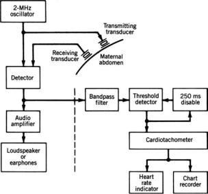
A block diagram of a typical indirect fetal heart rate monitoring system using Doppler ultrasound is shown in Fig. 4(b). As continuous wave ultrasound is used, separate adjacent transducers are employed to establish the ultrasonic beam and detect the Doppler-shifted reflected waves. The reflected ultrasound signal is mixed with the transmitted wave, and beat frequencies are produced when a Doppler shift in frequency occurs for the reflected wave.
Figure 4. Block diagram of a Doppler ultrasound indirect fetal heart rate monitor. [Reprinted with permission from CRC Press (6).]
This beat frequency is amplified and used to indicate the occurrence of a heartbeat to a cardiotachometer. Many monitors also provide this signal to a loudspeaker to assist the clinical personnel in positioning the transducers for optimal signal pickup or for auditory monitoring.
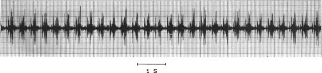
The reflected ultrasound signal is different from an electrocardiogram, although it can also be used to identify various events in the cardiac cycle. A typical signal is illustrated in Fig. 5. Here one sees two principal peaks per heartbeat, one corresponding to valve opening and the other to valve closing. Actually, such signals can be quite useful in measuring fetal systolic time intervals, but from the standpoint of the cardiotachometer for determining heart rate, they can create problems. If the cardiotachometer is set to trigger at the peak of each wave it sees, as it is for the electrocardiogram, it could measure two beats per cardiac cycle and would give an erroneously high fetal heart rate. One way to avoid this problem is to detect only the first peak of the signal, and, once it is detected, to disable the detection circuit for a period of time that is less than the shortest expected beat-to-beat interval but longer than the time necessary for the second Doppler-shifted signal to occur. In this way, only one peak per cardiac cycle will be registered.
A second, more sophisticated method for detecting the fetal heartbeat involves the use of short-range autocorrelation techniques. The monitor recognizes the beat signal from the reflected wave for a given cardiac cycle and looks for a signal that most closely correlates with this signal over the period of time in which the next heartbeat is likely to occur. The time interval between that time when the initial wave was measured and the point of best correlation corresponds to a beat-to-beat interval of the fetal heart. Thus, instead of relying only on the peaks of the ultrasound signal, this method looks at the entire signal and, therefore, is more accurate. Some manufacturers of commercial fetal monitors claim their ultrasonic systems using this
FETAL MONITORING |
291 |
Figure 5. Illustration of the raw reflected ultrasound signal from the beating fetal heart in utero. Note that two ultrasonic bursts occur per cardiac cycle.
type of autocorrelation technique can detect fetal heartbeats as well as can be done by the direct electrocardiographic technique.
The major limitations of the Doppler ultrasound technique are related to its sensitivity to movement. As the Doppler effect will respond to movements of any tissue interfaces illuminated by the ultrasound beam with respect to the signal source, movement of the mother or fetus can result in Doppler-shifted reflected waves that are stronger than the cardiac signal, which, with artifact, can completely obliterate the signal of interest. Thus, this technique is really only reliable when the patient is resting quietly, and it often fails to provide reliable information in the active phase of labor. The other movement-related problem is that the fetus can move in utero so that the heart is no longer illuminated by the ultrasound beam or the orientation of the heart with respect to the ultrasonic beam is such that it produces only a minimum. Doppler shift in the reflected ultrasonic wave. Thus, while monitoring a patient, it sometimes necessary to reposition the ultrasonic sensors on the maternal abdomen from time to time because of the movement of the fetus.
Acoustic Pickup of the Fetal Heart. Until the advent of electronic fetal monitoring, the standard method of detecting the fetal heartbeat to measure the fetal heart rate was to use a fetoscope. When the bell of this instrument was firmly pressed against the maternal abdomen, fetal heart sounds could be heard and the heart rate could be determined from them. The acoustic method of indirect fetal heart monitoring follows the fetal heartbeat by a similar technique (7). A sensitive contact microphone is placed on the maternal abdomen over the point where the loudest fetal heart sounds are heard with a fetoscope. The signal picked up by this microphone is filtered to improve the signal-to-noise ratio, and the resulting signal drives a cardiotachometer to give the instantaneous fetal heart rate. The acoustic signal from the fetal heart is similar to the Doppler ultrasound signal in that it generally has two components per heartbeat. The cardiotachometer is set to trigger when the peak signal comes from the acoustic transducer, so it is possible that two apparent fetal heartbeats can exist for each cardiac cycle. Thus, as was the case for the Doppler ultrasound, it is wise to have a processing circuit that selects only the first of the two heart sounds to trigger the cardiotachometer. Unlike the ultrasonic Doppler signal, the fetal heart sounds produce
sharp pulses that are narrower so that the detection of the time of the peak can be more precise. Thus, it is generally more accurate to measure the beat-to-beat interval using a peak detector with the acoustic signal than it is with the Doppler ultrasound. The use of the electrocardiogram still represents the best way to measure beat-to-beat cardiac intervals.
The major limitation of the acoustic method of detecting fetal heart sounds is the poor selectivity of the acoustic transducer. It not only is sensitive to the fetal heart sounds, but it will also respond to any other intraabdominal sounds in its vicinity. Also, a finite sensitivity to environmental sounds, exists which is an especially severe limitation for patients in active labor on a busy, noisy delivery service. For this reason, the acoustic method is limited primarily to patients who can lie quietly in a quiet environment to be monitored. The advent and use of the home-like labor/ delivery rooms has helped to create an atmosphere that is more conducive to acoustic fetal heart monitoring, yet it is still not a widely applied approach.
The acoustic technique also has the limitation that when used for antepartum (before labor and delivery) monitoring the fetus can move such that the microphone is no longer ideally positioned to pick up the fetal heart sounds. Thus, it is frequently necessary to relocate the microphone on the maternal abdomen with this monitoring approach.
The major advantages of the acoustic method lie in the fact that not only is there better accuracy in determining the instantaneous fetal heart rate, but unlike the ultrasound method, which must illuminate the fetus with ultrasonic energy, the acoustic method derives its energy entirely from the fetus, and no possibility exists of placing the fetus at risk due to exogenous energy. As a result, investigators have considered the possibility of using the acoustic method for monitoring the high-risk fetus at home (8).
Abdominal Electrocardiogram. Although the fetus is bathed in amniotic fluid located within the electrically conductive uterus and maternal abdomen, one can still see small potentials on the surface of the maternal abodomen that correspond to the fetal electrocardiogram. These signals are generally very weak, ranging in amplitude from 50 to 300 mV. Methods of obtaining the abdominal fetal electrocardiogram and clinical application of the information have been known for many years as described by
292 FETAL MONITORING
Larks (9), yet signal quality remains a major problem. Nevertheless, some methods of improving the quality of the signal have been developed. These methods can allow a much more detailed fetal electrocardiogram to be obtained from the maternal abdomen under ideal conditions, and such electrocardiograms can be used in some cases for more detailed diagnosis than from just looking at heart rate. One of these methods involves applying signalaveraging techniques to several subsequent fetal heartbeats using the fetal R wave as the time reference (10). In this way, the full P-QRS-T wave configuration can be shown, but heart rate information and its variability will be lost.
As the fetal electrocardiogram at the maternal abdominal surface is very weak, it is easy for other signals and noise to provide sufficient interference to completely obliterate the fetal signal. Having the subject rest quietly during the examination and removing the stratum corneum of the skin at the electrode sites can reduce noise due to motion artifact and electromyograms from the abdominal muscles. Nevertheless, one major interference source exists that requires other types of signal processing to eliminate. This source is the component of the maternal electrocardiogram seen on the abdominal leads. This signal is generally considerably higher in amplitude than the fetal signal. Thus, observation of the fetal electrocardiogram could be greatly improved by the elimination or at least the reduction of the maternal signal. One method of reducing this signal involves simultaneously recording the maternal electrocardiogram from chest electrodes and subtracting an appropriate component of this signal from the abdominal lead so that only the fetal signal remains. Under idealized circumstances, this process can give a greatly improved abdominal fetal electrocardiogram, but the conditions for subtraction of the maternal signal are likely to vary during a recording session so that frequent adjustments may be necessary to maintain the absence of the maternal signal (11).
The abdominal fetal electrocardiogram can be used for antepartum fetal heart monitoring. In this case, the goal of the instrumentation is to collect fetal R-R intervals as done with the direct monitoring of the fetal electrocardiogram and to determine the instantaneous heart rate from these intervals, which strong maternal component in the abdominal fetal electrocardiogram can make a very difficult task electronically, and so most abdominal fetal electrocardiogram fetal heart rate monitors need to eliminate the maternal component of the abdominal signal. The substraction method described in the previous paragraph would be ideal for this purpose because if fetal and maternal heartbeats occur in approximately the same time, subtracting the maternal component should leave the fetal component unaffected. Unfortunately, because the conditions under which the maternal component is added to the fetal signal change from one minute to the next, it is not always practical to use this subtraction technique. Thus, a simpler technique that loses more information is used.
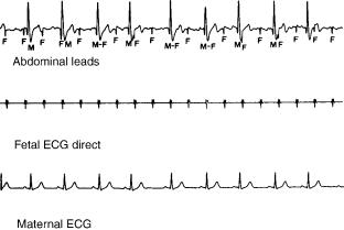
A typical abdominal fetal electrocardiogram is shown in Fig. 6 (lower panel) along with a direct fetal electrocardiogram taken from a scalp electrode and the maternal electrocardiogram taken from a chest lead. In the abdominal
Figure 6. An example of a fetal electrocardiogram as obtained from the maternal abdomen. F, fetal QRS complexes; M, maternal QRS complexes. The direct fetal electrocardiogram and maternal electrocardiogram are recorded simultaneously for comparison. [Reprinted with permission from CRC Press (6).]
fetal electrocardiogram, fetal heartbeats are indicated by F and maternal heartbeats by M. Note that some beats exist where the fetal and maternal heartbeats occur at the same time. The strategy of the abdominal fetal electrocardiogram/fetal heart rate monitor is to monitor two signals, the maternal electrocardiogram from a chest lead and the fetal and maternal electrocardiograms from an abdominal lead. As shown in the block diagram in Fig. 7, the maternal electrocardiogram triggers a gate such that the input from the abdominal lead is interrupted every time a maternal beat occurs. Thus, this process eliminates the maternal component from the abdominal signal, but it can also eliminate a fetal QRS complex if it occurs at a time close to or during the maternal QRS complex. Thus, the cardiotachometer estimates the intervals where one or more fetal beats is missing. Due to the random relationship between maternal and fetal heartbeats, it is most likely that only one fetal beat would be missing at a time because of this mechanism, and so when maternal and fetal beats coincide, the fetal R-R interval should be approximately double the previous interval. Some monitors look for this condition and imply that it is the result of simultaneous maternal and fetal beats. The monitor, therefore, artificially introduces a fetal beat at the time of the maternal beat so that an abrupt (and presumably incorrect) change in the fetal heart rate will not occur.
Although such processing of the fetal signal makes the resulting heart rate recordings appear to have less artifact, this technique can loose some important information. For example, if the fetus suffers from a cardiac arrhythmia such as second-degree heart block, in which the fetal heart can miss a beat every so often, the monitor would reintroduce the missing beat, and this arrhythmia would not be detected. The principal advantage of the abdominal electrocardiogram method of fetal heart rate monitoring is that it can, under optimal conditions, provide the closest indirect observation of the fetal heart rate as compared with direct observations. No risk to the patient exists from this procedure, and inexpensive disposable electrodes can be used as the sensors.

FETAL MONITORING |
293 |
Figure 7. Block diagram of a monitor for processing the abdominal electrocardiogram shown in Fig. 6 using the anticoincidence detector method. [Reprinted with permission from CRC Press (6).]
The limitations of this method include its being based on a very weak signal in an environment that can contain a great amount of artifact. Thus, low signal-to-noise ratios are frequently encountered. Patients must be resting quietly for the method to work. Furthermore, electrodes must be optimally placed for good results, which requires some experimentation with different electrode sites, and skill is required on the part of the user in finding optimal electrode positions for a particular patient. Various signal processing techniques have been used over the years to get a more reliable fetal signal from the abdominal surface, but most of these techniques only improve signal quality under very special circumstances (12,13).
UTERINE CONTRACTIONS
Although the fetal heart rate is an important fetal variable for clinical monitoring, an equally important maternal variable is uterine activity. In fetal monitoring, one must detect the occurrence of uterine contractions, their frequency, their duration, and their intensity. As was the case with the fetal heart rate, it is possible to monitor uterine contractions by both direct methods and indirect methods.
Direct Monitoring of Uterine Contractions
Uterine contractions are periodic coordinated contractions of the myometrium, the muscle of the uterine wall. In an ideal method of direct measurement of uterine contractions, the tension and displacement of the myometrium would be measured, but this measurement cannot be done for routine fetal monitoring as only invasive methods of making this measurement exist. Uterine contractions, however, are reflected in increases in hydrostatic pressure of the amniotic fluid within the pregnant uterus. If this fluid is continuous and in a closed system, pressure increases resulting from uterine contractions should be seen throughout the amniotic fluid and should be related to the overall strength of the contraction but not necessa-
rily to the tension at any one particular location in the myometrium.
The pressure change in the amniotic fluid during a contraction can be measured directly by coupling the amniotic fluid to a manometer, which consists of an electrical pressure sensor and the appropriate electronic circuitry for processing and indicating or recording the measured pressure. Intrauterine pressure can be measured by placing the pressure sensor directly in the amniotic fluid or by using a fluid-filled catheter to couple the amniotic fluid to an external pressure sensor. This latter method is the method most frequently employed in clinical fetal monitoring. The catheter used for coupling the amniotic fluid to an external pressure sensor can be placed only when the membranes surrounding the fetus have been ruptured, which should only be done if the patient is in labor. Unfortunately, rupture of the fetal membranes sometimes occurs spontaneously before the patient goes into labor or when the patient is in premature labor. It is unwise to place a catheter under these circumstances unless labor will be induced and the patient will deliver within 24 h. The reason is that the catheter can serve as a conduit for introducing infectious agents into the uterus or such agents can be introduced during the process of placing the catheter. When the distal tip of the catheter is within the amniotic fluid and its proximal end is connected to a pressure sensor at the same elevation as the distal end, the pressure seen at the sensor will, according to Pascal’s law, be the same as that in the amniotic fluid. Thus, when a contraction occurs, the pressure increase will be transmitted along the catheter to the external pressure sensor.
Although the fluid-filled catheter provides a direct conduit from the amniotic fluid to the externally located pressure sensor, it can also be responsible for measurement errors. As was pointed out earlier, the proximal and distal ends of the catheter must be at the same level if one is to avoid the gravitational hydrostatic errors that give incorrect baseline pressure readings. Pascal’s law applies only to the static solution where no fluid movement exists in the system. Once fluid movement occurs in the catheter,
294 FETAL MONITORING
pressure drops along the length of the catheter can result. Such fluid movement can occur when a small leak in the plumbing system exists at the sensor end of the catheter. Movement of the catheter itself or of the patient with respect to the pressure sensor can also produce alterations in the observed dynamic pressure. The most serious violation of Pascal’s law is that once the fetal membranes have been ruptured, a truly closed system no longer exists. The fetal head or other presenting part approximated against the cervix does, indeed, isolate the intrauterine amniotic fluid from the outside world, but amniotic fluid can leak through the cervix, thus, no longer providing a static situation. Furthermore, after membranes have been ruptured, the total amount of amniotic fluid in the uterine cavity is reduced. It is possible that there might be local non-communicating pools of amniotic fluid delineated by fetal parts on one side and by the uterine wall on the other. The pressure in one of these isolated pools possibly can be different from that of another. The measured pressure will, therefore, be dependent on which pool contains the distal tip of the catheter. A statistical study by Knoke et al. has shown that when three identical catheters are placed in the pregnant uterus, the pressure measured by each can be considerably different, and differences of more than 10 mmHg (1.3 kPa) can be seen between different sensors (14), which is probably due to the fact that the distal tip of each catheter is located in a different part of the uterus and is coupled to a pocket of amniotic fluid at a different pressure.
Other problems exist that can affect the quality of intrauterine pressure measurement with the catheterexternal sensor method. Poor recordings are obtained when catheter when catheter placement is not optimal and when limited communication exists between the fluid in the catheter and the intrauterine amniotic fluid. Many catheters in use today have a single hole either in the end or at the side of the catheter that communicates with the amniotic fluid. Mucus or vernix caseosa (a substance of a consistency similar to soft cheese that is found on the fetus) can obstruct or partially obstruct this opening resulting in poor quality recordings. When the distal tip of an openended intrauterine catheter becomes obstructed, the obstruction can frequently be ‘‘blown’’ off by forcing fluid through the catheter. In practice, this procedure is done by attaching a syringe filled with normal physiologic saline at the proximal end of the catheter near the pressure sensor and introducing fluid into the catheter when an obstruction is suspected.
It is possible to minimize these obstruction problems by modifying the catheter (15). Increasing the number of openings at the catheter tip is one of the simplest ways of minimizing obstructions. By placing an open-celled sponge on the catheter tip, it is possible to obtain a greater surface area in contact with the amniotic fluid because of the multiple openings of the sponge, which also tends to keep the tip of the catheter away from fetal or uterine structures, minimizing the possibility of complete obstruction or injury to the fetus. A small balloon placed at the distal tip of the catheter will prevent the fluid in the catheter from making actual contact with the amniotic fluid, and so this interface cannot be obstructed. As the
wall of the balloon is flexible, the pressure in the fluid within the balloon will be equal to the pressure in the fluid surrounding the balloon plus the pressure resulting from the tension in the balloon wall itself. This system, however, has the disadvantage that it will respond to a direct force on the balloon as well as to hydrostatic pressure in the fluid outside of the balloon; thus, fetal movements or the entrapment of the balloon between the fetus and the uterine wall during a contraction can lead to erroneous pressure measurements.
Interuterine pressure can be directly measured using a miniature pressure sensor that can be placed in the intrauterine cavity (16). These devices are based on a miniature silicon pressure sensor that can be placed on the tip of a probe that has a similar appearance to an intrauterine catheter. In some cases, the probe at the catheter tip is no longer than the catheter itself, so the method of placement is the same as that used for the catheter. The advantage of the intrauterine pressure sensor is its location within the uterine cavity, which aviods artifact introduced by the fluid-filled catheter, and the problem of zeroing the pressure measurement system due to elevation differences is avoided because the sensor is at the pressure source. Investigators have compared the performance of intrauterine sensors with that of intrauterine catheters and have found the newer devices to provide equivalent data to the previously accepted technology (17).
Indirect Monitoring of Uterine Contractions
The clinician is able to sense uterine contractions by palpating (feeling) the maternal abdomen. Indirect uterine contraction sensors known as tocodynamometers are electrical sensors for doing the same thing. The basic principle of operation of these sensors is to press against the abdomen to measure the firmness of the underlying tissues. A contracting muscle will feel much more firm than a relaxed one. Most tocodynamometers carry out this function by pressing a probe against the abdomen and measuring its displacement.
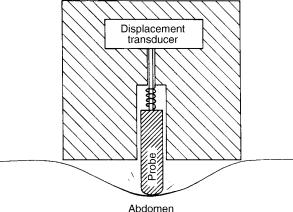
The construction of a typical tocodynamometer is shown in Fig. 8. The sensor is held in place against the surface of
Figure 8. Schematic cross-sectional view of a tocodynamometer. [Reprinted with permission from CRC Press (6).]
the abdomen with an elastic strap. A movable probe protrudes beyond the surface of the sensor so that it causes a slight indentation in the abdominal wall. It is loaded by a spring, which makes it somewhat compliant; it can be either extended further into the abdominal wall or retracted into the body of the sensor depending on the firmness of the tissue of the abdominal wall under the probe. In some tocodynamometers, the spring tension, and hence the force that the probe exerts on the abdomen wall, can be adjusted by means of a small knob so that optimal operation of the sensor can be achieved. What a uterine contraction occurs, the abdominal wall will become tense, and it tends to push the probe back into the housing of the tocodynamometer. Following the contraction, the spring is again able to push the probe deeper into the abdomen. In some tocodynamometers this actual movement is very slight, whereas in others it can be as great as a few millimeters.
A displacement sensor inside the tocodynamometer provides an electrical signal proportional to the position of the probe. This displacement reflects myometrial activity. Different types of displacement sensors can be used in tocodynamometers. Including a strain gage on a cantilever arm, mutual inductance coils, a linear variable differential transformer, or a piezoelectric crystal.
The principal advantage of the tocodynamometer is the noninvasive way in which it measures uterine contractions. It is the only method that can be safely used before the patient is in active labor. It has serious limitations, however, in the quantitative assessment of labor. The method can be used only to quantitatively determine the frequency and duration of uterine contractions. Its output is only qualitative with respect to the strength of the contractions. Signal levels seen are a function of the position of the sensor on the maternal abdomen and the tension of the belt holding it in place. Signal amplitudes are also strongly related to maternal anatomy, and the method is virtually useless in obese patients. Many patients in active labor complain that the use of the tocodynamometer with a tight belt is uncomfortable and irritating.
Electronic Signal Processing
A block diagram for the uterine contraction channel of an electronic fetal monitor is illustrated in Fig. 9. The sensor can be either an internal or external pressure transducer or
FETAL MONITORING |
295 |
a tocodynamometer. Signals are sometimes filtered in the amplifier stages of the monitor because the uterine contraction information includes only dc and very low ac frequencies. Nevertheless, filtering is generally not necessary for high quality signals, and often the presence of artifact due to breathing movements of the patient is useful in demonstrating that the pressure measuring system is functional.
In some cases, it is necessary to adjust the baseline pressure to establish a zero reference pressure when using the monitor. In the case of direct uterine contraction monitoring when a single pressure sensor is always used with the same monitor, this adjustment should be made by the manufacturer, and additional adjustment should not be necessary. As a matter of fact, making such a zero-level adjustment control available to the operator of the monitor runs the risk of having significantly altered baseline pressures that can affect the interpretation of uterine basal tone. The adjustment of a zero-level control should not replace the requirement of having the proximal and distal end of the fluid-filled catheter at the same level. It is far better to adjust zero levels in uterine pressure monitoring by raising or lowering the external pressure transducer than by adjusting the electrical zero. On the other hand, when the tocodynamometer is used, no physiologically significant zero level exists. It is not possible to establish uterine basal tone with a tocodynamometer. Baseline levels are frequently dependent on how the tocodynamometer is attached to the patient and the structure of the sensor itself. In this case, it is reasonable to adjust the baseline level between uterine contractions so that the tracing conveniently fits on the chart. When doing so, it is important that the chart indicates that the uterine contractions were measured using a tocodynamometer so that the individual reading the chart does not ascribe inappropriate information to the baseline.
Uterine Electromyogram
The uterus is a muscle, and electrical signals are associated with its contraction as they are for any kind of muscle. These signals can be detected from electrodes on the maternal abdomen or the uterine cervix during uterine contractions. Garfield and others have studied these signals and suggested that they might be useful in managing
Figure 9. Block diagram of the signal processing electronics for intrauterine pressure measurement.
296 FETAL MONITORING
patients during pregnancy and, perhaps, even during labor (18–20). These techniques are still experimental and not yet ready for clinical application. Nevertheless, they offer a new approach to assessing uterine activity and the possibility of differentiating contractions leading to cervical dilatation from those that are nonprogressive.
THE FETAL CARDIOTOCOGRAPH
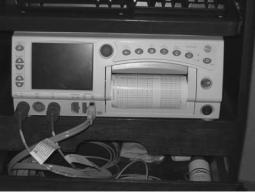
Electronic fetal monitoring is accomplished using a fetal cardiotocograph, such as illustrated in Fig. 10, which is basically a two-channel instrument with a two-channel chart recorder as the output indicator. One of the channels records the fetal heart rate, whereas the second channel records the uterine contractions. Most cardiotocographs are capable of accepting direct or indirect signals as inputs for each channel, although specialized monitors for antepartum assessment have only the indirect signal input capability. To aid clinicians in interpreting monitored patterns, most instruments use chart paper that is 70 mm wide for the fetal heart rate channel and calibrated from 30 to 240 beats min 1. The uterine contraction channel is 40 mm wide and calibrated with a scale from 0 to 100. The scale is only qualitative when a tocodynamometer is the input source, but corresponds to the pressure in millimeters of mercury when direct sensors of uterine contractions are used. The standard speeds for the chart paper are 1 or 3 cm/min. The use of a standardized chart and chart speed results in fetal heart rate—uterine contraction patterns that appear the same no matter what monitoring device is used—which is important because cardiotocograms are read by visually recognizing patterns on the chart. Changing the chart speed and scale significantly changes the appearance of the patterns even though the data remain unchanged. Thus, a clinician would have to learn to interpret patterns from each of the different types of monitors used if they each had different chart speeds and scales, because the same pattern can appear quite different when the chart speed or signal amplitude is changed.
Information Obtained from Fetal Cardiotocography
In interpreting a cardiotocogram, a clinician considers the heart rate and uterine contraction information separately
Figure 10. A commercially available fetal cardiotocograph. (Courtesy of Portage Health System, Hancock, Michigan.)
as well as the interaction between the two signals. The frequency, duraction, and, in the case of direct monitoring, amplitude and baseline information have already been discussed. Similar types of information can be obtained from the directly and indirectly monitored fetal heart rate recordings. Specifically in the fetal heart rate channel, one looks for the average baseline value of the fetal heart rate, which should generally be in the range 120–160 beats min 1 and when outside of this range can be cause for concern. The beat-to-beat variability of the fetal heart rate can also be an important indicator of fetal condition, and so the use of an instantaneous cardiotachometer in a cardiotocograph is mandatory. Certain recurring patterns in the fetal heart rate recording can also be important indicators of fetal condition. Sinusoidally varying fetal heart rate has been described as an ominous sign (21), and sometimes fetal cardiac arrhythmias can be detected by observing the heart rate pattern.
The information that is most frequently obtained from the cardiotocogram and applied clinically comes from both the heart rate and uterine contraction channels and is concerned with the relationship between these two signals. One can consider a uterine contraction as a stress applied to the fetus and the resulting changes in the fetal heart rate as the response to this stress. When the changes occur in direct relationship to the uterine contractions, they are referred to as periodic changes in the fetal heart rate. Several possibilities exist for fetal heart rate changes during and following a uterine contraction. One can see no change, an acceleration, or a deceleration in the fetal heart rate. In the case of decelerations, three basic patterns are seen, and representative examples of these are shown in Fig. 11. The different patterns are characterized by the shape of the deceleration curve and the temporal relationship of its onset and conclusion with the uterine contraction.
Early decelerations begin during the rising phase of the uterine contraction and return to baseline during the falling phase. They frequently appear to be almost the inverse of the uterine contraction waveform. Periodic decelerations of this type are thought to not represent a serious clinical problems.
Late decelerations refer to fetal heart rate decelerations that begin during a utterine contraction but late in the duration of that contraction. The rate of heart rate descent is not rapid, and the deceleration lasts beyond the end of the contraction and then slowly returns to baseline. Such patterns sometimes can be associated with fetal distress, although they should not be considered definitive of fetal distress.
The third type of periodic deceleration of the fetal heart rate is known as a variable deceleration. In this pattern, the deceleration of heart rate is sharp and can occur either early or late in the duration of the uterine contraction. Following the contraction, a rapid return to baseline values occurs. Sometimes one sees rapid return to baseline while the uterus is still contracting and then a rpaid fall back to the reduced heart rate. Variable decelerations have a flat ‘‘U’’ shape, whereas early and late decelerations represent a more smooth curve that could be characterized as shaped as the letter ‘‘V’’ with the negative peak rounded. Variable
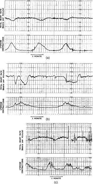
Figure 11. Examples of fetal cardiotocograms showing the three basic patterns: (a) early deceleration, (b) late deceleration, and (c) variable deceleration.
decelerations can be sometimes associated with involvement of the umbilical cord, and, in some cases, they can indicate the presence of fetal distress. As more recent clinical studies have shown that a simple relationship between late and variable decelerations and fetal compromise, does not exist these patterns are not considered to indicate fetal distress as they once were. Now clinicians refer to them as being ‘‘nonreassuring,’’ and their presence should encourage the application of other clinical measures to evaluate the fetus.
These basic thoughts for interpreting the fetal cardiotocogram are very elementary and should not be used for diagnostic purposes. The reader is referred to the current
FETAL MONITORING |
297 |
obstetrical literature for more detailed descriptions of fetal cardiotocogram and their clinical significance.
Clinical Applications of Fetal Cardiotocography
Electronic fetal monitoring can be applied during the antepartum (before labor and delivery) and intraparturn (during labor and delivery) periods of pregnancy. In the anterpartum period, only indirect methods of fetal monitoring can be used. A primary application of fetal cardiotocography in this period is in nonstress testing. In this test, a cardiotocograph is applied to a patient who is resting quietly. In the United States, the ultrasonic Doppler method of detecting the fetal heart rate and the tocodynamometer are the sensors of choice. The patient is monitored for 1–2 h, and the cardiotocogram is examined for spontaneously occurring uterine contractions of fetal movements, which can also be indicated by the tocodynamometer. In some cases, the mother is asked to activate an event marker on the chart when she feels a fetal movement. The response of the fetal heart rate to these stimuli is noted in interpreting the cardiotocogram. In a reactive nonstress test, a response to these stimuli occurs, which is usually in the form of a brief fetal heart rate acceleration following the uterine contraction or fetal movement. Although nonstress testing is not routinely applied to apparently normal pregnancies, it is indicated for complications of pregnancy such as maternal diabetes, Rh sensitization, intrauterine growth retardation , decreased fetal movement, known fetal anomalies, oligohydrainnios or poly-hydramnios (too little or too much amniotic fluid), pregnancy-induced hypertension, pregnancy lasting beyond the normal 40 weeks, and other maternal and fetal complications.
A second antepartum test involving fetal cardiotocography is the oxytocin challenge test, which is usually applied when the nonstress test yields positive results, such as when fetal heart rate decelerations follow spontaneous uterine contractions or fetal movements. In this test, the patient is given intravenous oxytocin, a hormone that stimulates uterine contractions. The response of the fetal heart rate to the induced contractions is then examined, looking for the periodic changes described before.
Intrapartum monitoring of the fetal heart and uterine contractions can be carried out using the indirect techniques in early labor with the direct techniques applied during active labor. The indications for intrapartum fetal monitoring are controversial. Some obstetricians feel that all labors should be monitored whether they are complicated or not, whereas others feel that only those patients considered being at risk should have monitors. As monitoring is no longer considered to give a definitive diagnosis of fetal distress, some clinicians find it of little value and to not make use of the technology. As internal monitoring gives the most efficacious results, this modality is recommended in cases when it can be applied and the indirect methods do not give satisfactory results. Otherwise, indirect methods can be used as long as they give readable results.
The preceding paragraphs describe fetal cardiotocography as clinically applied in most major medical centers. Although this technology has the advantage of providing
298 FETAL MONITORING
continuous surveillance of the mother and fetus, it also has some limitations that prevent if from providing optimal information to obtain the earliest indications of fetal or maternal problems. The major limitation is in the data. Although uterine contractions provide a good indication of the intensity of labor, they do not necessarily indicate its effectiveness in dilating the cervix and expelling the fetus. If, in addition to uterine contractions, one should monitor whether labor is progressing, better information about some maternal aspects of labor and delivery could be obtained.
A similar argument can be made for the use of the fetal heart rate as the primary variable for evaluating the status of the fetus. Heart rate is a very non specific variable, and, in same cases, the fetus must be seriously compromised before any problem is detected by the heart rate. The goal of fetal monitoring as mentioned at the beginning of this article is to make certain that vital organs such as the fetal brain are adequately perfused so as to receive necessary nutrients and oxygen. Although the heart rate is related, it is not the principal variable for determining this perfusion.
Accepting these principal limitations for the variables measured, limitations still exist to the practical application of the cardiotocograph. Sensor placement, especially for indirect monitoring, is important for optimal recordings. The operator of the instrumentation, therefore, must be skilled in determining the best placement for the sensors. Most cardiotocographs are connected to the sensors on the patients by wires and catheters. Although this method is quite adequate while the patient is in bed, it can become quite inconvenient when it is necessary to transfer the patient to another location or to have the patient stand up and walk around. Many of these problems have been overcome by the use of biotelemetry for fetal monitoring (see Biotelemetry).
A final limitation of fetal cardiotocography is associated with the fact that some of the monitored patterns are not easily recognized and interpreted, which means that different clinicians looking at the data can see different things, lead to uncertain diagnoses. Periodic decelerations are usually not as clear, as illustrated in Fig. 11. Again, experience is an important factor here. Even when patterns can be readily determined, the relationship between certain patterns and pathology is not completely clear. As is so often the case medicine, one can only suggest from monitored tracets that certain problems might be present, and other tests need to be performed for confirmation.
OTHER METHODS OF FETAL MONITORING
Although the cardiotocogram is the usual method used to monitor the fetus, other techniques have been developed and experimentally employed to more accurately assess fetal status during the antepartum and intrapartum periods. One of these techniques, fetal microblood analysis is routinely used at major medical centers that care for patients deemed to have high risk pregnancies; the other techniques are still experimental or relatively new and have not enjoyed routine application at the time of this writing.
Fetal Microblood Analysis
About the time when electronic fetal monitoring was developed, Saling (22) was working on a new technique for taking a small sample of fetal capillary blood during active labor and measuring its hydrogen ion activity. This technique, known as fetal microblood analysis, made it possible to determine whether acidosis that could be associated with fetal distress was present during the labor. The technique involves observing a portion of the fetal presenting part (usually the scalp) through the cervix using a vaginal endoscope. By cleaning this portion of fetal skin and even, in some cases, shaving a small amount of hair from the scalp, the obstetrician is able to make a small superifical incision in the skin using a scalpel blade. A droplet of capillary blood will form at this site, and it can be collected in a miniature heparinized glass pipet. Generally, 100–300 mL of blood can be collected in this way. The blood sample is transferred to a special instrument designed to measure the pH of very small blood specimens. This instrument can be a part of a more extensive blood gas analysis instruments in a blood gas laboratory or it can be a relatively simple bedside device that uses disposable pH sensor cartrnidges. In either case, it is possible to measure the pH of this small sample and get the results back to the clinician within a few minutes of collecting the sample.
Chronic hypoxia can cause tissue and, hence, blood pH to drop as a result of the formation of acidic products of anaerobic metabolism such as lactic acid. Thus, if a blood sample is found to have a low pH (most clinical guidelines say lower than 7.2 or in some cases 7.15), it is possible that the fetus is experiencing some form of distress. Often, this technique is used in conjunction with fetal cardiotocography. When the cardiotocograph indicates possible fetal distress, such as when late decelerations are seen, the clinician can get a better idea as to whether distress is indeed present by performing a fetal microblood analysis. If the results indicate acidosis, the probability of actual fetal distress is higher, and appropriate actions can be taken.
A major limitation of the Saling technique is that it gives only an indication of the fetal acid-base status at the time the blood sample was taken. It would be far better to have a continuous or quasi-continuous measure of fetal tissue pH. Stamm et al. (23) have described a technique in which a miniature glass pH sensor is placed in the fetal scalp during active labor. This sensor can continuously record the pH of the fetal scalp. Clinical studies of this technique have shown that a drop in fetal tissue pH can occur along with a cardiotocographic indication of fetal distress (24). The major limitation of this as yet experimental technique is technical. The sensor is fragile, and it is not always possible to obtain efficacious recordings from it. Other sensor are under development in an attempt to overcome some of these limitations (25), yet this technique remains experimental due to the lack of practical devices.
Monitoring of Fetal Blood Gases
Many investigators have been interested in developing technology to continuously monitor fetal oxygenation during active labor and delivery. A review of some of the earlier techniques showed different types of oxygen sensors that
could be placed in the fetal scalp using structures similar to electrodes for directly obtaining the fetal electrocardiogram. Investigators also have used transcutaneous oxygen sensors on the fetus (26), and the most recent approach has been the uses of fetal pulse oximetry (27–29). In the transcutaneous oxygen case (see Blood Gas Measurement, Transcutaneous), a miniature sensor is attached to the fetal scalp once the cervix has dilated enough to make this physically possible, and fetal membranes have been ruptured. The technique is considerably more difficult than that for neonates, and it is important to have a preparation where the sensor surface is well approximated to the feal skin so no chance exists for environmental air to enter the electrode, as fetal Po2 is much lower than that of the air. Most investigators who use this technique experimentally find that gluing the sensor to a shaved region of fetal scalp is the best technique to maintain contact (26).
Fetal pulse oximetry is performed in a similar way, but the sensor probe does not have to be physically fixed to the fetus as was the case for the transcutaneous oxygen tension measurement described above (27–29). Instead, the probe is a flat, flexible structure that contains ligh-emitting diodes at two different wavelengths and photodetector for sensing the reflected light. It is slid between the fetal head and the cervix once the head is engaged and membranes have been ruptured and is oriented so that the light sources and detector are pressed against the fetal skin by the uterine wall. The reflected light at each wavelength will vary in intensity as the blood volume in the fetal tissue changes over the cardiac cycle. As with the routine clinical pulse oximeter, the ratio of amplitudes of the reflected light at the different wavelengths is used to determine the oxygen saturation of the fetal arterial blood.
Recent improvements in the technology of making transcutaneous carbon dioxide sensors have allowed miniature transcutaneous sensors to be built in the laboratory. These have been applied to the fetus during active labor to continuously measure carbon dioxide tensions (30). All of these transcutaneous methods of measuring fetal blood gases are experimental at the time of this writing and have limitations regarding the technique of application and the quality of recorded information. Nevertheless, they present an interesting new approach to monitoring the fetus using variables more closely related to fetal metabolism and, hence, with greater potential for accurately detecting fetal distress.
Fetal Activity and Movements
The amount of time that the fetus spends in different activity states may be an important indicator of fetal condition. The fetus, as does the neonate, spends time in different activity states. Part of the time it may be awake and active, moving around in the uterus; at other times, it may be quiet and resting or sleeping. By establishing norms for the percentage of time that the fetus spends in these states, one can measure the activity of a particular fetus over a period of time and determine whether it falls within the normal classifications as a means of evaluating fetal condition.
One of the simplest ways to measure fetal activity is to have the mother indicate whether she feels fetal
FETAL MONITORING |
299 |
movements over a period of time, which can be done and recorded for several days as an assessment of fetal wellbeing. Fetal movements can also be detected by tocodynamometers. If the fetus is located under the probe of a tocodynamometer and moves or kicks, it can be detected as a short-duration pulse of activity on the chart recording from the sensor. Maternal movements can appear on this sensor as well, and so it is not easy to differentiate between the two. Timor-Trich et al. have developed a technique using two tocodynamometers to minimize this problem (31). By placing one over the fundus of the uterus and the second at a lower level, and recording the signals on adjacent channels of a chart recorder, fetal movements very often either are seen only on one sensor or produce pulses of opposite sign on the two sensors. Maternal movements, on the other hand, are usually seen on both sensors and are similar in shape and sign.
One of the most elegant methods of measuring fetal movements is to directly observe these movements using real-time ultrasonic imaging (see Ultrasonic Imaging). The main limitation of this technique is that an ultrasonographer must continuously operate the apparatus and reposition the ultrasonic transducer to maintain the best image. It also requires the subject to rest quietly during the examination. Although not believed to be a problem, no definite evidence currently exists that long-term exposure of the fetus to ultrasonic energy is completely safe.
One special type of fetal movement that is of interest to obstetricians is fetal breathing movement. The fetus goes through periods of in utero movement that are very similar to breathing movements. The relative percentage of these movements during a period of time may be indicative of fetal condition (32). Such movements can be observed using real-time ultrasound as described above. One can also select specific points on the chest and abdomen and use the ultrasonic instrument to record movements of these points as a function of time as one does for echocardiography (see Echocardiography). Measurement of fetal breathing movements by this technique also requires an experienced ultrasonographer to operate and position the instrumentation during examinations. For this reason, it is not a very practical technique for routine clinical application.
Fetal Electroencephalography
As one of the principal objectives of fetal monitoring is to determine if conditions are adequate to maintain fetal brain function, it is logical to consider a measure of this function as an appropriate measurement variable. The electroencephalogram (EEG) is one such measure that is routinely used in the neurological evaluation of patients. The EEG from the fetus during labor has been measured and shown to undergo changes commensurate with other indicators of fetal distress during labor and delivery (33,34). The monitoring of fetal EEG involves placement of two electrodes on the fetal scalp and measurement of the differential signal between them. These electrodes can be similar to the electrodes used for detecting the fetal electrocardiogram, or they can be electrodes especially designed for EEG. Of course, when either of these electrodes is used in the unipolar mode, the fetal electrocardiogram can be obtained.
300 FETAL MONITORING
Rosen et al. obtained good-quality fetal EEG recordings using a specially designed suction electrode (34). By observation of configurational or power spectrum changes in the EEG, it may be possible to indicate conditions of fetal distress.
Continuous Monitoring of Cervical Dilatation
In the routine method used to assess the progress of labor, the examiner places his or her fingers in the vagina and feels the uterine cervix to determine its length, position, and dilatation. Although this technique is simple and quick and requires no special apparatus, it has some limitations as well. It is an infrequent sampling method, and each time a measurement is made there can be discomfort for the patients as well as risk of intrauterine infection. The technique is also very subjective and depends on the experience of the examiner. A more reliable and reproducible technique that is capable of giving continuous records could be useful in the care of high-risk patients and patients with increased risk of intrauterine infection. Mechanical, caliper-like devices attached to opposite sides of the cervix have been described by Friedman (35) and others. These devices measure a cervical diameter with an electrical angular displacement transducer attached to the calipers. These devices are somewhat big and awkward, and Richardson et al. have optimised the mechanical structure by reducing its size (36). Other investigators have eliminated the mechanical calipers and used a magnetic field to measure the distance between two points on diametrically opposed sides of the cervix (37). In another technique for continuously monitoring cervical dilatation reported by Zador et al., ultrasound is used to measure the cervical diameter (38). A brief pulse of ultrasound is generated at a transducer on one side of the cervix and is detected, after propagating across the cervical canal, by a similar transducer on the opposite side. By measuring the transit time of the ultrasonic pulse between the two transducers, one can determine the distance between them, because ultrasound propagates through soft tissue a nearly constant known velocity. By generating an ultrasonic pulse once a second, a continuous recording of cervical dilatation as a function of time can be produced, which can be recorded either on an adjacent channel with the fetal cardiotocogram or on a separate display that generates a curve of cervical dilatation as a function of time known as a labor graph. Many clinicians plot such a curve as a result of their digital examinations of the cervix.
SUMMARY
As seen from this article, the use of biomedical instrumentation in obstetrical monitoring is fairly extensive, but the variables measured are not optimal in achieving the goals of fetal monitoring. Some of the newer and yet experimental techniques offer promise of getting closer to the question of whether vital structures in the fetus are being adequately perfused, but at the present time, none of these techniques are ready for general widespread application. Fetal monitoring is important if it can detect correctable fetal distress, as the results of such distress can remain with the newborn for life. It is important that the fetal
monitoring techniques used will eventually benefit this patient. Some critics of currently applied fetal cardiotocography claim that the only result of fetal monitoring has been increase in the number of cesarean sections performed, and this might have a negative rather than positive effect on patient care. It is important that as this area of biomedical instrumentation progresses, biomedical engineers, clinicians, and device manufacturers are not only concerned with the technology. Instead , true progress will be seen when measured variables and their analysis are more closely and more specifically related to fetal status, and measurements can be made in a less invasive way without disturbance or discomfort. The application of this technology must be a benefit to the patients and to society.
BIBLIOGRAPHY
Cited References
1.Hon EH. Apparatus for continuous monitoring of the fetal heart rate. Yale J,Biol Med 1960;32:397.
2.Shenker L. Fetal electrocardiography. Obstet,Gynecol Surv 1966;21:367.
3.LaCroix GE. Fetal electrocardiography in labor: A new scalp electrode. Mich Med 1968;67:976.
4.Hon EH. Instrumentation of fetal heart rate and fetal electrocardiography. II. A vaginal electrode. Am J Obstet Gynecol 1963;86:772.
5.Hon EH, Paul RH, Hon RW. Electrode evaluation of the fetal heart rate. XI. Description of a spiral electrode. Obstet Gynecol 1972;40:362.
6.Roux JF, Neuman MR, Goodlin RC. Monitoring intrapartum phenomena. CRC Crit Rev Bioeng 1975;2:119.
7.Hammacher K. Neue methode zur selectiven registrierung der fetalen herzschlagfrequenz. Geburteh Frauenkeilk 1962;22:1542.
8.Talbert DO, Davies WL, Johnson F, Abraham N, Colley N, Southall DP. Wide bandwidth fetal phonography using a sensor matched to the compliance of the mother’s abdominal wall. IEEE Trans Biomed Eng 1986;BME-33:175.
9.Larks SD. Normal fetal electrocardiogram, statistical data and representative waveforms. Am J Obstet Gynecol 1964;90:1350.
10.Cox JR. An algorithmic approach to signal estimation useful in electrocardiography. IEEE Trans Biomed Eng 1969;BME16:3.
11.Nagel J, Schaldach M. Processing the abdominal fetal ECG using a new method. In: Rolfe P, editor. Fetal and Neonatal Physiological Measurements. London: Pitman; 1980. p. 9.
12.Tal Y, Akselrod S. A new method for fetal ECG detection. Comput Biomed Res 1991;24(3):296–306.
13.Assaleh K, Al-Nashash H. A novel technique for the extraction of fetal ECG using polynomial networks. IEEE Trans Biomed Eng 2005;52(6):1148–1152.
14.Knoke JD, Tsao LL, Neuman MR, Roux JF. The accuracy of measurements of intrauterine pressure during labor: A statistical analysis. Comput Biomed Res 1976;9:177.
15.Csapo A. The diagnostic significance of the intrauterine pressure. Obstet Gynecol Surv 1970;25:403–515.
16.Neuman MR, Picconnatto J, Roux JF. A wireless radiotelemetry system for monitoring fetal heart rate and intrauterine pressure during labor and delivery. Gynecol Invest 1970;1(2):92–104.
17.Devoe LD, Gardner P, Dear C, Searle N. Monitoring intrauterine pressure during active labor. A prospective comparison of two methods. J Reprod Med 1989;34(10):811–814.