- •Warning and Disclaimer
- •Feedback Information
- •Trademark Acknowledgments
- •About the Author
- •About the Technical Reviewers
- •Dedication
- •Acknowledgments
- •Contents at a Glance
- •Contents
- •Icons Used in This Book
- •Command Syntax Conventions
- •Cisco’s Motivation: Certifying Partners
- •Format of the CCNA Exams
- •What’s on the CCNA Exams
- •ICND Exam Topics
- •Cross-Reference Between Exam Topics and Book Parts
- •CCNA Exam Topics
- •INTRO and ICND Course Outlines
- •Objectives and Methods
- •Book Features
- •How This Book Is Organized
- •Part I: LAN Switching
- •Part II: TCP/IP
- •Part III: Wide-Area Networks
- •Part IV: Network Security
- •Part V: Final Preparation
- •Part VI: Appendixes
- •How to Use These Books to Prepare for the CCNA Exam
- •For More Information
- •Part I: LAN Switching
- •“Do I Know This Already?” Quiz
- •Foundation Topics
- •Brief Review of LAN Switching
- •The Forward-Versus-Filter Decision
- •How Switches Learn MAC Addresses
- •Forwarding Unknown Unicasts and Broadcasts
- •LAN Switch Logic Summary
- •Basic Switch Operation
- •Foundation Summary
- •Spanning Tree Protocol
- •“Do I Know This Already?” Quiz
- •Foundation Topics
- •Spanning Tree Protocol
- •What IEEE 802.1d Spanning Tree Does
- •How Spanning Tree Works
- •Electing the Root and Discovering Root Ports and Designated Ports
- •Reacting to Changes in the Network
- •Spanning Tree Protocol Summary
- •Optional STP Features
- •EtherChannel
- •PortFast
- •Rapid Spanning Tree (IEEE 802.1w)
- •RSTP Link and Edge Types
- •RSTP Port States
- •RSTP Port Roles
- •RSTP Convergence
- •Edge-Type Behavior and PortFast
- •Link-Type Shared
- •Link-Type Point-to-Point
- •An Example of Speedy RSTP Convergence
- •Basic STP show Commands
- •Changing STP Port Costs and Bridge Priority
- •Foundation Summary
- •Virtual LANs and Trunking
- •“Do I Know This Already?” Quiz
- •Foundation Topics
- •Review of Virtual LAN Concepts
- •Trunking with ISL and 802.1Q
- •ISL and 802.1Q Compared
- •VLAN Trunking Protocol (VTP)
- •How VTP Works
- •VTP Pruning
- •Foundation Summary
- •Part II: TCP/IP
- •IP Addressing and Subnetting
- •“Do I Know This Already?” Quiz
- •Foundation Topics
- •IP Addressing Review
- •IP Subnetting
- •Analyzing and Interpreting IP Addresses and Subnets
- •Math Operations Used to Answer Subnetting Questions
- •Converting IP Addresses from Decimal to Binary and Back Again
- •The Boolean AND Operation
- •How Many Hosts and How Many Subnets?
- •What Is the Subnet Number, and What Are the IP Addresses in the Subnet?
- •Finding the Subnet Number
- •Finding the Subnet Broadcast Address
- •Finding the Range of Valid IP Addresses in a Subnet
- •Finding the Answers Without Using Binary
- •Easier Math with Easy Masks
- •Which Subnet Masks Meet the Stated Design Requirements?
- •What Are the Other Subnet Numbers?
- •Foundation Summary
- •“Do I Know This Already?” Quiz
- •Foundation Topics
- •Extended ping Command
- •Distance Vector Concepts
- •Distance Vector Loop-Avoidance Features
- •Route Poisoning
- •Split Horizon
- •Split Horizon with Poison Reverse
- •Hold-Down Timer
- •Triggered (Flash) Updates
- •RIP and IGRP
- •IGRP Metrics
- •Examination of RIP and IGRP debug and show Commands
- •Issues When Multiple Routes to the Same Subnet Exist
- •Administrative Distance
- •Foundation Summary
- •“Do I Know This Already?” Quiz
- •Foundation Topics
- •Link-State Routing Protocol and OSPF Concepts
- •Steady-State Operation
- •Loop Avoidance
- •Scaling OSPF Through Hierarchical Design
- •OSPF Areas
- •Stub Areas
- •Summary: Comparing Link-State and OSPF to Distance Vector Protocols
- •Balanced Hybrid Routing Protocol and EIGRP Concepts
- •EIGRP Loop Avoidance
- •EIGRP Summary
- •Foundation Summary
- •“Do I Know This Already?” Quiz
- •Foundation Topics
- •Route Summarization and Variable-Length Subnet Masks
- •Route Summarization Concepts
- •VLSM
- •Route Summarization Strategies
- •Sample “Best” Summary on Seville
- •Sample “Best” Summary on Yosemite
- •Classless Routing Protocols and Classless Routing
- •Classless and Classful Routing Protocols
- •Autosummarization
- •Classful and Classless Routing
- •Default Routes
- •Classless Routing
- •Foundation Summary
- •Advanced TCP/IP Topics
- •“Do I Know This Already?” Quiz
- •Foundation Topics
- •Scaling the IP Address Space for the Internet
- •CIDR
- •Private Addressing
- •Network Address Translation
- •Static NAT
- •Dynamic NAT
- •Overloading NAT with Port Address Translation (PAT)
- •Translating Overlapping Addresses
- •Miscellaneous TCP/IP Topics
- •Internet Control Message Protocol (ICMP)
- •ICMP Echo Request and Echo Reply
- •Destination Unreachable ICMP Message
- •Time Exceeded ICMP Message
- •Redirect ICMP Message
- •Secondary IP Addressing
- •FTP and TFTP
- •TFTP
- •MTU and Fragmentation
- •Foundation Summary
- •Part III: Wide-Area Networks
- •“Do I Know This Already?” Quiz
- •Foundation Topics
- •Review of WAN Basics
- •Physical Components of Point-to-Point Leased Lines
- •Data-Link Protocols for Point-to-Point Leased Lines
- •HDLC and PPP Compared
- •Looped Link Detection
- •Enhanced Error Detection
- •Authentication Over WAN Links
- •PAP and CHAP Authentication
- •Foundation Summary
- •“Do I Know This Already?” Quiz
- •Foundation Topics
- •ISDN Protocols and Design
- •Typical Uses of ISDN
- •ISDN Channels
- •ISDN Protocols
- •ISDN BRI Function Groups and Reference Points
- •ISDN PRI Function Groups and Reference Points
- •BRI and PRI Encoding and Framing
- •PRI Encoding
- •PRI Framing
- •BRI Framing and Encoding
- •DDR Step 1: Routing Packets Out the Interface to Be Dialed
- •DDR Step 2: Determining the Subset of the Packets That Trigger the Dialing Process
- •DDR Step 3: Dialing (Signaling)
- •DDR Step 4: Determining When the Connection Is Terminated
- •ISDN and DDR show and debug Commands
- •Multilink PPP
- •Foundation Summary
- •Frame Relay
- •“Do I Know This Already?” Quiz
- •Foundation Topics
- •Frame Relay Protocols
- •Frame Relay Standards
- •Virtual Circuits
- •LMI and Encapsulation Types
- •DLCI Addressing Details
- •Network Layer Concerns with Frame Relay
- •Layer 3 Addressing with Frame Relay
- •Frame Relay Layer 3 Addressing: One Subnet Containing All Frame Relay DTEs
- •Frame Relay Layer 3 Addressing: One Subnet Per VC
- •Frame Relay Layer 3 Addressing: Hybrid Approach
- •Broadcast Handling
- •Frame Relay Service Interworking
- •A Fully-Meshed Network with One IP Subnet
- •Frame Relay Address Mapping
- •A Partially-Meshed Network with One IP Subnet Per VC
- •A Partially-Meshed Network with Some Fully-Meshed Parts
- •Foundation Summary
- •Part IV: Network Security
- •IP Access Control List Security
- •“Do I Know This Already?” Quiz
- •Foundation Topics
- •Standard IP Access Control Lists
- •IP Standard ACL Concepts
- •Wildcard Masks
- •Standard IP ACL: Example 2
- •Extended IP Access Control Lists
- •Extended IP ACL Concepts
- •Extended IP Access Lists: Example 1
- •Extended IP Access Lists: Example 2
- •Miscellaneous ACL Topics
- •Named IP Access Lists
- •Controlling Telnet Access with ACLs
- •ACL Implementation Considerations
- •Foundation Summary
- •Part V: Final Preparation
- •Final Preparation
- •Suggestions for Final Preparation
- •Preparing for the Exam Experience
- •Final Lab Scenarios
- •Scenario 1
- •Scenario 1, Part A: Planning
- •Solutions to Scenario 1, Part A: Planning
- •Scenario 2
- •Scenario 2, Part A: Planning
- •Solutions to Scenario 2, Part A: Planning
- •Part VI: Appendixes
- •Glossary
- •Answers to the “Do I Know This Already?” Quizzes and Q&A Questions
- •Chapter 1
- •“Do I Know This Already?” Quiz
- •Chapter 2
- •“Do I Know This Already?” Quiz
- •Chapter 3
- •“Do I Know This Already?” Quiz
- •Chapter 4
- •“Do I Know This Already?” Quiz
- •Chapter 5
- •“Do I Know This Already?” Quiz
- •Chapter 6
- •“Do I Know This Already?” Quiz
- •Chapter 7
- •“Do I Know This Already?” Quiz
- •Chapter 8
- •“Do I Know This Already?” Quiz
- •Chapter 9
- •“Do I Know This Already?” Quiz
- •Chapter 10
- •“Do I Know This Already?” Quiz
- •Chapter 11
- •“Do I Know This Already?” Quiz
- •Chapter 12
- •“Do I Know This Already?” Quiz
- •Using the Simulation Software for the Hands-on Exercises
- •Accessing NetSim from the CD
- •Hands-on Exercises Available with NetSim
- •Scenarios
- •Labs
- •Listing of the Hands-on Exercises
- •How You Should Proceed with NetSim
- •Considerations When Using NetSim
- •Routing Protocol Overview
- •Comparing and Contrasting IP Routing Protocols
- •Routing Through the Internet with the Border Gateway Protocol
- •RIP Version 2
- •The Integrated IS-IS Link State Routing Protocol
- •Summary of Interior Routing Protocols
- •Numbering Ports (Interfaces)
404 Chapter 11: Frame Relay
Example 11-7 frame-relay map Commands
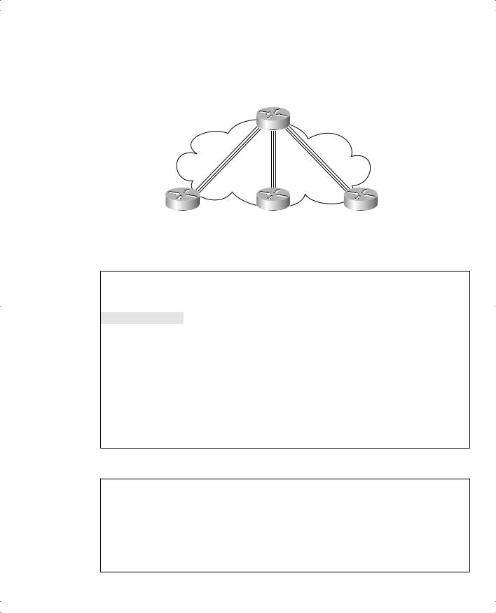
Mayberry
interface serial 0
no frame-relay inverse-arp
frame-relay map ip 199.1.1.2 52 broadcast frame-relay map ip 199.1.1.3 53 broadcast
Mount Pilot
interface serial 0
no frame-relay inverse-arp
frame-relay map ip 199.1.1.1 51 broadcast frame-relay map ip 199.1.1.3 53 broadcast
Raleigh
interface serial 0
no frame-relay inverse-arp
frame-relay map ip 199.1.1.1 51 broadcast frame-relay map ip 199.1.1.2 52 broadcast
The frame-relay map command entry for Mayberry, referencing 199.1.1.2, is used for packets in Mayberry going to Mount Pilot. When Mayberry creates a Frame Relay header, expecting it to be delivered to Mount Pilot, Mayberry must use DLCI 52. Mayberry’s map statement correlates Mount Pilot’s IP address, 199.1.1.2, to the DLCI used to reach Mount Pilot—namely, DLCI 52. Likewise, a packet sent back from Mount Pilot to Mayberry causes Mount Pilot to use its map statement to refer to Mayberry’s IP address of 199.1.1.1. Mapping is needed for each next-hop Layer 3 address for each Layer 3 protocol being routed. Even with a network this small, the configuration process can be laborious.
A Partially-Meshed Network with One IP Subnet Per VC
The second sample network, based on the environment shown in Figure 11-19, uses point- to-point subinterfaces. Examples 11-8 through 11-11 show the configuration for this network. The command prompts are included in the first example because they change when you configure subinterfaces.
Frame Relay Configuration 405
Figure 11-19 Partial Mesh with IP Addresses
140.1.11.0/24
|
|
|
|
|
|
DLCI 51 |
0/24.2.1140 . |
|
Atlanta |
||
|
|||||
140 |
|
140 |
|||
.0/24 |
|
|
1 |
||
.1 |
|
|
. |
||
|
|
3 |
|||
.1 |
|
|
. |
||
|
|
. |
|||
|
|
|
0/24 |
Frame Relay
Partial Mesh
DLCI 52 |
|
s0 DLCI 53 |
|
|
DLCI 54 |
|||||
|
|
s0 |
|
|
|
|
s0 |
|||
Charlotte |
|
Nashville |
|
|
|
|
Boston |
|||
|
|
|
|
|
||||||
|
|
|
|
|
|
|
|
|
|
|
140.1.12.0/24 |
140.1.13.0/24 |
|
140.1.14.0/24 |
|
Example 11-8 Atlanta Configuration
Atlanta(config)#interface serial0
Atlanta(config-if)#encapsulation frame-relay
Atlanta(config-if)#interface serial 0.1 point-to-point
Atlanta(config-subif)#ip address 140.1.1.1 255.255.255.0
Atlanta(config-subif)#frame-relay interface-dlci 52
Atlanta(config-fr-dlci)#interface serial 0.2 point-to-point
Atlanta(config-subif)#ip address 140.1.2.1 255.255.255.0
Atlanta(config-subif)#frame-relay interface-dlci 53
Atlanta(config-fr-dlci)#interface serial 0.3 point-to-point
Atlanta(config-subif)#ip address 140.1.3.1 255.255.255.0
Atlanta(config-subif)#frame-relay interface-dlci 54
Atlanta(config-fr-dlci)#interface ethernet 0
Atlanta(config-if)#ip address 140.1.11.1 255.255.255.0
Example 11-9 Charlotte Configuration
interface serial0 encapsulation frame-relay
!
interface serial 0.1 point-to-point ip address 140.1.1.2 255.255.255.0 frame-relay interface-dlci 51
!
interface ethernet 0
ip address 140.1.12.2 255.255.255.0
406 Chapter 11: Frame Relay
Example 11-10 Nashville Configuration
interface serial0 encapsulation frame-relay
!
interface serial 0.2 point-to-point ip address 140.1.2.3 255.255.255.0 frame-relay interface-dlci 51
!
interface ethernet 0
ip address 140.1.13.3 255.255.255.0
Example 11-11 Boston Configuration
interface serial0 encapsulation frame-relay
!
interface serial 0.3 point-to-point ip address 140.1.3.4 255.255.255.0 frame-relay interface-dlci 51
!
interface ethernet 0
ip address 140.1.14.4 255.255.255.0
Again, defaults abound in this configuration, but some defaults are different than when you’re configuring on the main interface, as in the preceding example. The LMI type is autosensed, and Cisco encapsulation is used, which is just like the fully-meshed example. However, Inverse ARP is disabled on each point-to-point subinterface by default. As you will see, Inverse ARP is not needed with point-to-point subinterfaces.
Two new commands create the configuration required with point-to-point subinterfaces. First, the interface serial 0.1 point-to-point command creates logical subinterface number 1 under physical interface Serial0. The frame-relay interface-dlci subinterface subcommand then tells the router which single DLCI is associated with that subinterface.
An example of how the interface-dlci command works can help. Consider router Atlanta in Figure 11-19. Atlanta receives LMI messages on Serial0 stating that three PVCs, with DLCIs 52, 53, and 54, are up. Which PVC goes with which subinterface? Cisco IOS software needs to associate the correct PVC with the correct subinterface. This is accomplished with the frame-relay interface-dlci command.
Frame Relay Configuration 407
The subinterface numbers do not have to match on the router on the other end of the PVC, nor does the DLCI number. In this example, I just numbered them to be easier to remember! In real life, it is useful to encode some information about your network numbering scheme into the subinterface number. One client I worked with encoded part of the carrier’s circuit ID in the subinterface number so that the operations staff could find the correct information to tell the Telco when troubleshooting the link. Many sites use the DLCI as the subinterface number. Of course, useful troubleshooting information, such as the DLCI, the name of the router on the other end of the VC, and so on, could be configured as text with the description command as well. In any case, there are no requirements for matching subinterface numbers. Here, all I did was match the subinterface number to the third octet of the IP address.
Example 11-12 shows the output from the most popular Cisco IOS software Frame Relay
EXEC commands for monitoring Frame Relay, as issued on router Atlanta.
Example 11-12 Output from EXEC Commands on Atlanta
Atlanta#show frame-relay pvc
PVC Statistics for interface Serial0 (Frame Relay DTE)
|
Active |
Inactive |
Deleted |
Static |
Local |
3 |
0 |
0 |
0 |
Switched |
0 |
0 |
0 |
0 |
Unused |
0 |
0 |
0 |
0 |
DLCI = 52, DLCI USAGE = LOCAL, |
PVC STATUS |
= ACTIVE, |
INTERFACE = Serial0.1 |
||
input pkts 843 |
output pkts 876 |
|
in bytes 122723 |
||
|
|
|
|
||
out bytes 134431 |
dropped pkts 0 |
|
in FECN pkts 0 |
||
in |
BECN pkts 0 |
out FECN pkts 0 |
|
out BECN pkts 0 |
|
in |
DE pkts 0 |
out DE pkts 0 |
|
|
|
out bcast pkts 876 |
out bcast bytes 134431 |
|
|||
pvc create time 05:20:10, last time pvc |
status changed 05:19:31 |
||||
--More-- |
|
|
|
|
|
DLCI |
= 53, DLCI USAGE = LOCAL, PVC STATUS |
= ACTIVE, INTERFACE = Serial0.2 |
|||
input pkts 0 |
output pkts 875 |
|
in bytes 0 |
||
out bytes 142417 |
dropped pkts 0 |
|
in FECN pkts 0 |
||
in |
BECN pkts 0 |
out FECN pkts 0 |
|
out BECN pkts 0 |
|
in |
DE pkts 0 |
out DE pkts 0 |
|
|
|
out bcast pkts 875 |
out bcast bytes 142417 |
|
|||
pvc create time 05:19:51, last time pvc |
status changed 04:55:41 |
||||
--More-- |
|
|
|
|
|
DLCI |
= 54, DLCI USAGE = LOCAL, PVC STATUS |
= ACTIVE, INTERFACE = Serial0.3 |
input pkts 10 out bytes 142069 in BECN pkts 0
output pkts 877 dropped pkts 0 out FECN pkts 0
in bytes 1274 in FECN pkts 0 out BECN pkts 0
continues
408 Chapter 11: Frame Relay
Example 11-12 Output from EXEC Commands on Atlanta (Continued)
in DE pkts 0 |
|
out DE pkts 0 |
|
out bcast pkts |
877 |
out bcast bytes 142069 |
|
pvc create time 05:19:52, last time pvc |
status changed 05:17:42 |
||
Atlanta#show frame-relay map |
|
||
|
|
||
Serial0.3 (up): point-to-point dlci, dlci |
54(0x36,0xC60), broadcast |
||
status |
defined, active |
|
|
Serial0.2 (up): point-to-point dlci, dlci |
53(0x35,0xC50), broadcast |
||
status |
defined, active |
|
|
Serial0.1 (up): point-to-point dlci, dlci |
52(0x34,0xC40), broadcast |
||
status |
defined, active |
|
Atlanta#debug frame-relay lmi
Frame Relay LMI debugging is on
Displaying all Frame Relay LMI data
Serial0(out): StEnq, myseq 163, yourseen 161, DTE up datagramstart = 0x45AED8, datagramsize = 13
FR encap = 0xFCF10309
00 75 01 01 01 03 02 A3 A1
Serial0(in): Status, myseq 163
RT IE 1, length 1, type 1
KA IE 3, length 2, yourseq 162, myseq 163
The show frame-relay pvc command lists useful management information. For instance, the packet counters for each VC, plus the counters for FECN and BECN, can be particularly useful. Likewise, comparing the packets/bytes sent on one router versus the counters of what is received on the router on the other end of the VC is also quite useful, because it reflects the number of packets/bytes lost inside the Frame Relay cloud. Also, the PVC status is a great place to start when troubleshooting. In addition, an SNMP manager can better gather all this information with this command.
The show frame-relay map command lists mapping information. With the earlier example of a fully-meshed network, in which the configuration did not use any subinterfaces, a Layer 3 address was listed with each DLCI. In this example, a DLCI is listed in each entry, but no mention of corresponding Layer 3 addresses is made. The whole point of mapping is to correlate a Layer 3 address to a Layer 2 address, but there is no Layer 3 address in the show frame-relay map command output! The reason is that the information is stored somewhere else. Subinterfaces require the use of the frame-relay interface-dlci configuration command. Because these subinterfaces are point-to-point, when a route points out a single subinterface,