


340 Chapter 10: ISDN and Dial-on-Demand Routing
The router needs to route packets so that they are queued to go out the dial interface. Cisco’s design for DDR defines that the router receives some user-generated traffic and, through normal routing processes, decides to route the traffic out the interface to be dialed. The router (SanFrancisco) can receive a packet that must be routed out BRI0; routing the packet out BRI0 triggers the Cisco IOS software, causing the dial to occur.
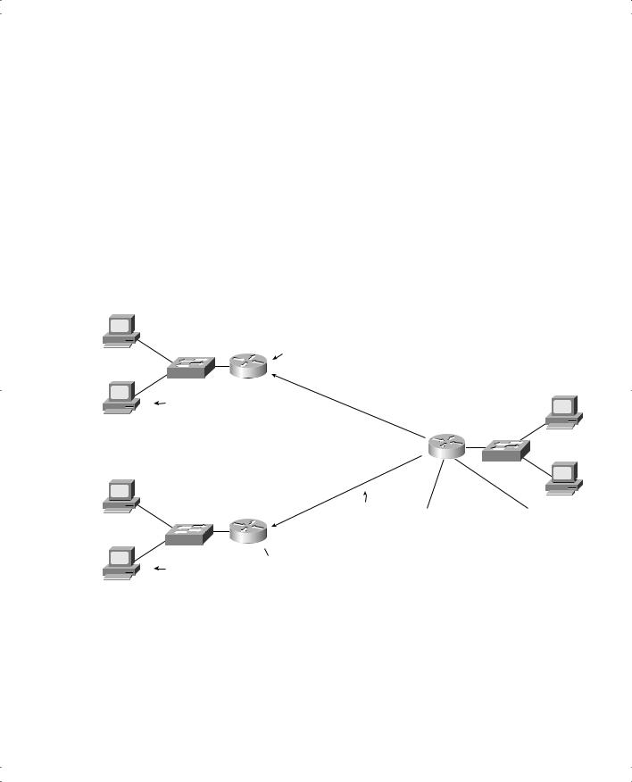
Of course, routing protocols cannot learn routes over a BRI line that is not normally up! In Figure 10-5, for example, SanFrancisco has no routes to 172.16.3.0/24 learned via a routing protocol, because no B channel call has been placed yet. Therefore, static routes must be configured on SanFrancisco, pointing to subnets in LosAngeles. Then, packets are routed out the interface, which can trigger a dial of a B channel to LosAngeles.
All routable protocols can be configured to trigger the dial by routing packets of that type out the interface. Because IP is so popular, it is used in the upcoming examples.
To begin the process of building a DDR configuration, IP routes are added to the configuration so that packets can be directed out BRI0 on SanFrancisco, as shown in Example 10-1. This static route points out interface BRI0, because SanFrancisco's BRI0 interface is in the same subnet as 172.16.2.1.
Example 10-1 Defining a Static Route to Send Packets Out the ISDN BRI Interface
! SanFrancisco static routes
ip route 172.16.3.0 255.255.255.0 172.16.2.1
DDR Step 2: Determining the Subset of the Packets That Trigger the Dialing Process
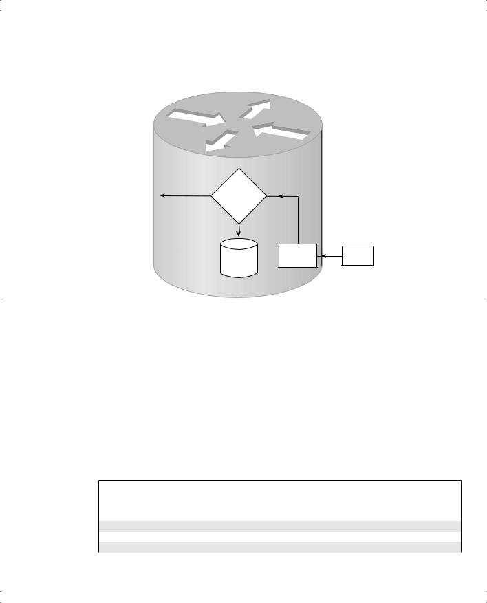
Together, Steps 1 and 2 of Legacy DDR logic determine when to dial a circuit. These combined steps are typically called triggering the dial. In Step 1, a packet is routed out an interface to be dialed, but that alone does not necessarily cause the dial to occur. The Cisco IOS software allows Step 2 to define a subset of the packets routed in Step 1 to actually cause the route to dial. The logic flow is shown in Figure 10-6.
The choice in Step 2 is simply put like this: “Is this packet, which is being routed out this dial interface, worthy of causing the dial to occur?” Cisco calls packets that are worthy of causing the device to dial interesting packets. Cisco does not name packets that are not worthy of causing the dial; in effect, they are “boring.” Only interesting packets cause the dial to occur, but when the circuit is up, both interesting and boring traffic can flow across the link.
The network engineer has control over what causes the dial, meaning that he or she also controls when the router spends the company’s money. Providers typically charge a base fee for the ISDN line, plus incremental charges per minute of use for a B channel.

342 Chapter 10: ISDN and Dial-on-Demand Routing
Example 10-2 Defining Interesting Packets to Activate the Circuit from SanFrancisco to LosAngeles (Continued)
!
interface bri 0 encapsulation ppp
ip address 172.16.2.2 255.255.255.0
!Use this one if all IP is considered interesting ...
dialer-group 1
!
!OR use next statement to trigger for web to server Lois
!Note: If you typed the next command, it would replace the dialer-group 1
!command; only one dialer-group is allowed per interface!
!
dialer-group 2
The dialer-group interface subcommand enables the logic that determines what is interesting. It refers to a dialer-list, which can refer to either an entire protocol suite (as seen in dialer-list 1) or an access list (as seen in dialer-list 2). With dialer-group 1 under interface BRI0, any IP traffic that tries to exit the interface is considered interesting and causes a dial to occur.
The other dialer list in the example, dialer-list 2, refers to IP access list number 101. If the access list matches a packet that has been routed out interface BRI0, the router dials. If the ACL matching logic does not match the packet, the dial does not occur. This allows you to choose specific subsets of IP traffic that cause the dial to occur. (Chapter 12 has more information on Cisco ACLs.)
DDR Step 3: Dialing (Signaling)
Before the router can dial, or signal, to set up a call, it needs to know the phone number of the other router. With the network shown in Figure 10-5, the configuration is straightforward. The command is dialer string string, where string is the phone number. Example 10-3 completes the DDR configuration associated with Figure 10-5 that allows the dial to occur.
Example 10-3 SanFrancisco Configuration: Dialing Can Now Occur
ip route 172.16.3.0 255.255.255.0 172.16.2.1
!
access-list 101 permit tcp any host 172.16.3.1 eq 80
!
dialer-list 2 protocol ip list 101
!
interface bri 0
ip address 172.16.2.2 255.255.255.0 encapsulation ppp
dialer string 14045551234 dialer-group 2

 BRI0 172.16.4.0/24
  172.16.1.0/24
344 Chapter 10: ISDN and Dial-on-Demand Routing
Example 10-4 shows the mostly complete configuration. CHAP configuration has been added in this step as well.
Example 10-4 SanFrancisco Configuration: Two Dial-To Sites with a Dialer Map in Use
ip route 172.16.3.0 255.255.255.0 172.16.2.1 ip route 172.16.4.0 255.255.255.0 172.16.2.3
!Added usernames for CHAP support! username LosAngeles password Clark username GothamCity password Bruce
access-list 101 permit tcp any host 172.16.3.1 eq 80
!Added next statement to make The Client’s FTP connection interesting! access-list 101 permit tcp any host 172.16.4.1 eq 21
dialer-list 2 protocol ip list 101
interface bri 0
ip address 172.16.2.2 255.255.255.0 encapsulation ppp
ppp authentication chap
dialer map ip 172.16.2.1 broadcast name LosAngeles 14045551234 dialer map ip 172.16.2.3 broadcast name GothamCity 19999999999 dialer-group 2
!
router igrp 6 network 172.16.0.0
The dialer map commands imply that if the interesting packet were routed to 172.16.2.1, the dial to LosAngeles would occur. Similarly, if an interesting packet were routed to 172.16.2.3, the dial to GothamCity would occur. The definition of interesting is expanded to include packets to the FTP server in GothamCity.
Two other important configuration elements are included in Example 10-4. First, CHAP authentication is configured. PAP or CHAP is required if you’re dialing to more than one site with ISDN—and PAP and CHAP require PPP. Notice that the usernames and password used with the two remote routers are shown near the top of the configuration. Because SanFrancisco gets CHAP challenges from two different remote sites, it must somehow know which router is sending the CHAP request. So, the username that SanFrancisco expects from the other router is based on the name parameter in the dialer map command.
You should also note the importance of the broadcast keyword on the dialer map commands. Just as with any other point-to-point serial link, there is no true data-link broadcast. If a broadcast must be sent on the interface after the circuit has been created, you must use the broadcast keyword to tell the interface to forward the packet across the link.