- •Warning and Disclaimer
- •Feedback Information
- •Trademark Acknowledgments
- •About the Author
- •About the Technical Reviewers
- •Dedication
- •Acknowledgments
- •Contents at a Glance
- •Contents
- •Icons Used in This Book
- •Command Syntax Conventions
- •Cisco’s Motivation: Certifying Partners
- •Format of the CCNA Exams
- •What’s on the CCNA Exams
- •ICND Exam Topics
- •Cross-Reference Between Exam Topics and Book Parts
- •CCNA Exam Topics
- •INTRO and ICND Course Outlines
- •Objectives and Methods
- •Book Features
- •How This Book Is Organized
- •Part I: LAN Switching
- •Part II: TCP/IP
- •Part III: Wide-Area Networks
- •Part IV: Network Security
- •Part V: Final Preparation
- •Part VI: Appendixes
- •How to Use These Books to Prepare for the CCNA Exam
- •For More Information
- •Part I: LAN Switching
- •“Do I Know This Already?” Quiz
- •Foundation Topics
- •Brief Review of LAN Switching
- •The Forward-Versus-Filter Decision
- •How Switches Learn MAC Addresses
- •Forwarding Unknown Unicasts and Broadcasts
- •LAN Switch Logic Summary
- •Basic Switch Operation
- •Foundation Summary
- •Spanning Tree Protocol
- •“Do I Know This Already?” Quiz
- •Foundation Topics
- •Spanning Tree Protocol
- •What IEEE 802.1d Spanning Tree Does
- •How Spanning Tree Works
- •Electing the Root and Discovering Root Ports and Designated Ports
- •Reacting to Changes in the Network
- •Spanning Tree Protocol Summary
- •Optional STP Features
- •EtherChannel
- •PortFast
- •Rapid Spanning Tree (IEEE 802.1w)
- •RSTP Link and Edge Types
- •RSTP Port States
- •RSTP Port Roles
- •RSTP Convergence
- •Edge-Type Behavior and PortFast
- •Link-Type Shared
- •Link-Type Point-to-Point
- •An Example of Speedy RSTP Convergence
- •Basic STP show Commands
- •Changing STP Port Costs and Bridge Priority
- •Foundation Summary
- •Virtual LANs and Trunking
- •“Do I Know This Already?” Quiz
- •Foundation Topics
- •Review of Virtual LAN Concepts
- •Trunking with ISL and 802.1Q
- •ISL and 802.1Q Compared
- •VLAN Trunking Protocol (VTP)
- •How VTP Works
- •VTP Pruning
- •Foundation Summary
- •Part II: TCP/IP
- •IP Addressing and Subnetting
- •“Do I Know This Already?” Quiz
- •Foundation Topics
- •IP Addressing Review
- •IP Subnetting
- •Analyzing and Interpreting IP Addresses and Subnets
- •Math Operations Used to Answer Subnetting Questions
- •Converting IP Addresses from Decimal to Binary and Back Again
- •The Boolean AND Operation
- •How Many Hosts and How Many Subnets?
- •What Is the Subnet Number, and What Are the IP Addresses in the Subnet?
- •Finding the Subnet Number
- •Finding the Subnet Broadcast Address
- •Finding the Range of Valid IP Addresses in a Subnet
- •Finding the Answers Without Using Binary
- •Easier Math with Easy Masks
- •Which Subnet Masks Meet the Stated Design Requirements?
- •What Are the Other Subnet Numbers?
- •Foundation Summary
- •“Do I Know This Already?” Quiz
- •Foundation Topics
- •Extended ping Command
- •Distance Vector Concepts
- •Distance Vector Loop-Avoidance Features
- •Route Poisoning
- •Split Horizon
- •Split Horizon with Poison Reverse
- •Hold-Down Timer
- •Triggered (Flash) Updates
- •RIP and IGRP
- •IGRP Metrics
- •Examination of RIP and IGRP debug and show Commands
- •Issues When Multiple Routes to the Same Subnet Exist
- •Administrative Distance
- •Foundation Summary
- •“Do I Know This Already?” Quiz
- •Foundation Topics
- •Link-State Routing Protocol and OSPF Concepts
- •Steady-State Operation
- •Loop Avoidance
- •Scaling OSPF Through Hierarchical Design
- •OSPF Areas
- •Stub Areas
- •Summary: Comparing Link-State and OSPF to Distance Vector Protocols
- •Balanced Hybrid Routing Protocol and EIGRP Concepts
- •EIGRP Loop Avoidance
- •EIGRP Summary
- •Foundation Summary
- •“Do I Know This Already?” Quiz
- •Foundation Topics
- •Route Summarization and Variable-Length Subnet Masks
- •Route Summarization Concepts
- •VLSM
- •Route Summarization Strategies
- •Sample “Best” Summary on Seville
- •Sample “Best” Summary on Yosemite
- •Classless Routing Protocols and Classless Routing
- •Classless and Classful Routing Protocols
- •Autosummarization
- •Classful and Classless Routing
- •Default Routes
- •Classless Routing
- •Foundation Summary
- •Advanced TCP/IP Topics
- •“Do I Know This Already?” Quiz
- •Foundation Topics
- •Scaling the IP Address Space for the Internet
- •CIDR
- •Private Addressing
- •Network Address Translation
- •Static NAT
- •Dynamic NAT
- •Overloading NAT with Port Address Translation (PAT)
- •Translating Overlapping Addresses
- •Miscellaneous TCP/IP Topics
- •Internet Control Message Protocol (ICMP)
- •ICMP Echo Request and Echo Reply
- •Destination Unreachable ICMP Message
- •Time Exceeded ICMP Message
- •Redirect ICMP Message
- •Secondary IP Addressing
- •FTP and TFTP
- •TFTP
- •MTU and Fragmentation
- •Foundation Summary
- •Part III: Wide-Area Networks
- •“Do I Know This Already?” Quiz
- •Foundation Topics
- •Review of WAN Basics
- •Physical Components of Point-to-Point Leased Lines
- •Data-Link Protocols for Point-to-Point Leased Lines
- •HDLC and PPP Compared
- •Looped Link Detection
- •Enhanced Error Detection
- •Authentication Over WAN Links
- •PAP and CHAP Authentication
- •Foundation Summary
- •“Do I Know This Already?” Quiz
- •Foundation Topics
- •ISDN Protocols and Design
- •Typical Uses of ISDN
- •ISDN Channels
- •ISDN Protocols
- •ISDN BRI Function Groups and Reference Points
- •ISDN PRI Function Groups and Reference Points
- •BRI and PRI Encoding and Framing
- •PRI Encoding
- •PRI Framing
- •BRI Framing and Encoding
- •DDR Step 1: Routing Packets Out the Interface to Be Dialed
- •DDR Step 2: Determining the Subset of the Packets That Trigger the Dialing Process
- •DDR Step 3: Dialing (Signaling)
- •DDR Step 4: Determining When the Connection Is Terminated
- •ISDN and DDR show and debug Commands
- •Multilink PPP
- •Foundation Summary
- •Frame Relay
- •“Do I Know This Already?” Quiz
- •Foundation Topics
- •Frame Relay Protocols
- •Frame Relay Standards
- •Virtual Circuits
- •LMI and Encapsulation Types
- •DLCI Addressing Details
- •Network Layer Concerns with Frame Relay
- •Layer 3 Addressing with Frame Relay
- •Frame Relay Layer 3 Addressing: One Subnet Containing All Frame Relay DTEs
- •Frame Relay Layer 3 Addressing: One Subnet Per VC
- •Frame Relay Layer 3 Addressing: Hybrid Approach
- •Broadcast Handling
- •Frame Relay Service Interworking
- •A Fully-Meshed Network with One IP Subnet
- •Frame Relay Address Mapping
- •A Partially-Meshed Network with One IP Subnet Per VC
- •A Partially-Meshed Network with Some Fully-Meshed Parts
- •Foundation Summary
- •Part IV: Network Security
- •IP Access Control List Security
- •“Do I Know This Already?” Quiz
- •Foundation Topics
- •Standard IP Access Control Lists
- •IP Standard ACL Concepts
- •Wildcard Masks
- •Standard IP ACL: Example 2
- •Extended IP Access Control Lists
- •Extended IP ACL Concepts
- •Extended IP Access Lists: Example 1
- •Extended IP Access Lists: Example 2
- •Miscellaneous ACL Topics
- •Named IP Access Lists
- •Controlling Telnet Access with ACLs
- •ACL Implementation Considerations
- •Foundation Summary
- •Part V: Final Preparation
- •Final Preparation
- •Suggestions for Final Preparation
- •Preparing for the Exam Experience
- •Final Lab Scenarios
- •Scenario 1
- •Scenario 1, Part A: Planning
- •Solutions to Scenario 1, Part A: Planning
- •Scenario 2
- •Scenario 2, Part A: Planning
- •Solutions to Scenario 2, Part A: Planning
- •Part VI: Appendixes
- •Glossary
- •Answers to the “Do I Know This Already?” Quizzes and Q&A Questions
- •Chapter 1
- •“Do I Know This Already?” Quiz
- •Chapter 2
- •“Do I Know This Already?” Quiz
- •Chapter 3
- •“Do I Know This Already?” Quiz
- •Chapter 4
- •“Do I Know This Already?” Quiz
- •Chapter 5
- •“Do I Know This Already?” Quiz
- •Chapter 6
- •“Do I Know This Already?” Quiz
- •Chapter 7
- •“Do I Know This Already?” Quiz
- •Chapter 8
- •“Do I Know This Already?” Quiz
- •Chapter 9
- •“Do I Know This Already?” Quiz
- •Chapter 10
- •“Do I Know This Already?” Quiz
- •Chapter 11
- •“Do I Know This Already?” Quiz
- •Chapter 12
- •“Do I Know This Already?” Quiz
- •Using the Simulation Software for the Hands-on Exercises
- •Accessing NetSim from the CD
- •Hands-on Exercises Available with NetSim
- •Scenarios
- •Labs
- •Listing of the Hands-on Exercises
- •How You Should Proceed with NetSim
- •Considerations When Using NetSim
- •Routing Protocol Overview
- •Comparing and Contrasting IP Routing Protocols
- •Routing Through the Internet with the Border Gateway Protocol
- •RIP Version 2
- •The Integrated IS-IS Link State Routing Protocol
- •Summary of Interior Routing Protocols
- •Numbering Ports (Interfaces)
Frame Relay Configuration 397
A Fully-Meshed Network with One IP Subnet
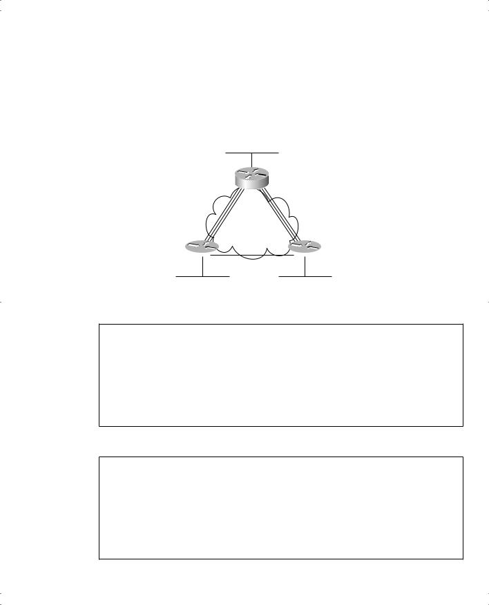
In this first example, the configuration uses all default values, and it does not use subinterfaces. The Frame Relay configuration is listed under the physical interfaces. Examples 11-1, 11-2, and 11-3 show the configuration for the network shown in Figure 11-16.
Figure 11-16 Full Mesh with IP Addresses
Subnet 199.1.10.0/24
|
Mayberry |
|
|
|
199.1.1.1 |
|
s0 |
|
|
Frame Relay |
|
199.1.1.2 |
Full Mesh |
199.1.1.3 |
s0 |
|
s0 |
Mount Pilot Raleigh
Subnet 199.1.11.0/24 |
Subnet 199.1.12.0/24 |
Example 11-1 Mayberry Configuration
interface serial0 encapsulation frame-relay
ip address |
199.1.1.1 |
255.255.255.0 |
! |
|
|
interface ethernet 0 |
|
|
ip address |
199.1.10.1 |
255.255.255.0 |
! |
|
|
router igrp |
1 |
|
network |
199.1.1.0 |
network |
199.1.10.0 |
Example 11-2 Mount Pilot Configuration
interface serial0 encapsulation frame-relay
ip address |
199.1.1.2 |
255.255.255.0 |
! |
|
|
interface ethernet 0 |
|
|
ip address |
199.1.11.2 |
255.255.255.0 |
! |
|
|
router igrp |
1 |
|
network |
199.1.1.0 |
network |
199.1.11.0 |
398 Chapter 11: Frame Relay
Example 11-3 Raleigh Configuration
interface serial0 encapsulation frame-relay
ip address |
199.1.1.3 |
255.255.255.0 |
! |
|
|
interface ethernet 0 |
|
|
ip address |
199.1.12.3 |
255.255.255.0 |
! |
|
|
router igrp |
1 |
|
network |
199.1.1.0 |
network |
199.1.12.0 |
The configuration is simple in comparison with the protocol concepts. The encapsulation frame-relay command tells the routers to use Frame Relay data-link protocols instead of the default, which is HDLC. Note that the IP addresses on the three routers’ serial interfaces are all in the same subnet. When you configure Frame Relay on the physical interfaces, all three routers must be in the same subnet.
Yes, Frame Relay configuration can be that easy, because IOS uses some very good choices for default settings:
■The LMI type is automatically sensed.
■The encapsulation is Cisco instead of IETF.
■PVC DLCIs are learned via LMI status messages.
■Inverse ARP is enabled (by default) and is triggered when the status message declaring that the VCs are up is received. (Inverse ARP is covered in the next section.)
In some cases, the default values are inappropriate. For example, you must use IETF encapsulation if one router is not a Cisco router. For the purpose of showing an alternative configuration, suppose that the following requirements were added:
■The Raleigh router requires IETF encapsulation on both VCs.
■Mayberry’s LMI type should be ANSI, and LMI autosense should not be used. Examples 11-4 and 11-5 show the changes that would be made to Mayberry and Raleigh.
Example 11-4 Mayberry Configuration with New Requirements
interface serial0 encapsulation frame-relay frame-relay lmi-type ansi
frame-relay interface-dlci 53 ietf ip address 199.1.1.1 255.255.255.0
! rest of configuration unchanged from Example 11-1.
Frame Relay Configuration 399
Example 11-5 Raleigh Configuration with New Requirements
interface serial0
encapsulation frame-relay ietf
ip address 199.1.1.3 255.255.255.0
!
! rest of configuration unchanged from Example 11-3.
These configurations differ from the previous ones in two ways: Raleigh changed its encapsulation for both its PVCs with the ietf keyword on the encapsulation command. This keyword applies to all VCs on the interface. However, Mayberry cannot change its encapsulation in the same way, because only one of the two VCs terminating in Mayberry needs to use IETF encapsulation—the other needs to use Cisco encapsulation. So Mayberry is forced to code the frame-relay interface-dlci command, referencing the DLCI for the VC to Raleigh, with the ietf keyword. With that command, you can change the encapsulation setting per-VC, as opposed to the configuration on Raleigh, which changes the encapsulation for all VCs.
The LMI configuration in Mayberry would be fine without any changes, because autosense would recognize ANSI. However, by coding the frame-relay lmi-type ansi command, Mayberry must use ANSI, because this command not only sets the LMI type, it also disables autonegotiation of the LMI type.
Mount Pilot needs to configure a frame-relay interface-dlci command with the ietf keyword for its VC to Raleigh, just like Mayberry. This change is not shown in the examples.
Frame Relay Address Mapping
Figure 11-16 does not even bother listing the DLCIs used for the VCs. The configurations work as stated, and frankly, if you never knew the DLCIs, this network would work! However, for the exam, and for real networking jobs, you need to understand an important concept related to Frame Relay—namely, Frame Relay address mapping. Figure 11-17 shows the same network, this time with Global DLCI values shown.
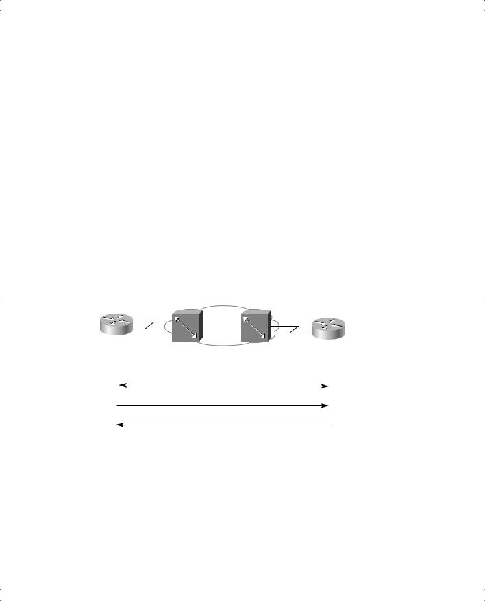
Frame Relay “mapping” creates a correlation between a Layer 3 address and its corresponding Layer 2 address. For example, the IP Address Resolution Protocol (ARP) cache used on LANs is an example of Layer 3-to-Layer 2 address mapping. With IP ARP, you know the IP address of another device on the same LAN, but not the MAC address; when the ARP completes, you know another device’s LAN (Layer 2) address. Similarly, routers that use Frame Relay need a mapping between a router’s Layer 3 address and the DLCI used to reach that other router.
400 Chapter 11: Frame Relay
Figure 11-17 Full Mesh with IP Addresses
|
|
|
|
Subnet 199.1.10.0/24 |
|||||||||
|
|
|
|
|
|
|
|
|
|
|
|
||
|
|
|
DLCI 51 |
|
|
Mayberry |
|||||||
|
|
|
|
||||||||||
|
|
|
|
|
|
|
|
|
199.1.1.1 |
|
|||
|
|
|
|
|
|
s0 |
|
|
|
|
|
||
199.1.1.2 |
|
|
|
Frame Relay |
|||||||||
|
|
|
Full Mesh |
199.1.1.3 |
|
||||||||
|
|
|
|
|
|
|
|
|
|
|
|||
|
|
|
|
s0 |
|
s0 |
|||||||
Mount Pilot |
|
|
|
|
|
|
|
|
|
Raleigh |
|||
|
|
|
|
|
|
|
|
||||||
|
|
|
|
|
|
|
|
||||||
|
|
|
|
DLCI 52 |
|
|
|
DLCI 53 |
|||||
|
|
|
|
|
|
|
|
||||||
Subnet 199.1.11.0/24 |
Subnet 199.1.12.0/24 |
This section discusses the basics of why mapping is needed for LAN connections and Frame Relay, with a focus on Frame Relay. Here’s a more general definition of mapping:
The information that correlates to the next-hop router’s Layer 3 address, and the Layer 2 address used to reach it, is called mapping. Mapping is needed on multiaccess networks.
Thinking about routing helps make the need for mapping more apparent. Imagine that a host on the Mayberry Ethernet sends an IP packet to a host on the Mount Pilot Ethernet. The packet arrives at the Mayberry router over the LAN, and Mayberry discards the Ethernet header and trailer. Mayberry looks at the routing table, which lists a route to 199.1.11.0, outgoing interface Serial0, and next-hop router 199.1.1.2, which is Mount Pilot’s Frame Relay IP address.
The next decision that the router must make to complete the process points out the need for mapping: What DLCI should Mayberry put in the Frame Relay header? We configured no DLCIs. However, it would work as configured! To see the answer, consider Example 11-6, which shows some important commands that can be used to see how Mayberry makes the right choice for the DLCI.
Example 11-6 show Commands on Mayberry, Showing the Need for Mapping
Mayberry#show ip route
Codes: C - connected, S - static, I - IGRP, R - RIP, M - mobile, B - BGP
D - EIGRP, EX - EIGRP external, O - OSPF, IA - OSPF inter area
N1 - OSPF NSSA external type 1, N2 - OSPF NSSA external type 2
E1 - OSPF external type 1, E2 - OSPF external type 2, E - EGP
i - IS-IS, L1 - IS-IS level-1, L2 - IS-IS level-2, ia - IS-IS inter area * - candidate default, U - per-user static route, o - ODR
Frame Relay Configuration 401
Example 11-6 show Commands on Mayberry, Showing the Need for Mapping (Continued)
P - periodic downloaded static route
Gateway of last resort is not set
I199.1.11.0/24 [100/8576] via 199.1.1.2, 00:00:26, Serial0 C 199.1.10.0/24 is directly connected, Ethernet0
I199.1.12.0/24 [100/8539] via 199.1.1.3, 00:01:04, Serial0 C 199.1.1.0/24 is directly connected, Serial0
C 192.68.1.0/24 is directly connected, Ethernet0 C 192.168.1.0/24 is directly connected, Ethernet0
Mayberry#show frame-relay pvc
PVC Statistics for interface Serial0 (Frame Relay DTE)
|
Active |
Inactive |
Deleted |
Static |
Local |
2 |
0 |
0 |
0 |
Switched |
0 |
0 |
0 |
0 |
Unused |
0 |
0 |
0 |
0 |
DLCI = 52, DLCI USAGE = LOCAL, PVC STATUS = ACTIVE, INTERFACE = Serial0
input pkts |
46 |
output pkts 22 |
in bytes 2946 |
out bytes 1794 |
dropped pkts 0 |
in FECN pkts 0 |
|
in BECN pkts 0 |
out FECN pkts 0 |
out BECN pkts 0 |
|
in DE pkts |
0 |
out DE pkts 0 |
|
out bcast pkts 21 |
out bcast bytes 1730 |
|
|
pvc create |
time 00:23:07, last time pvc status changed 00:21:38 |
DLCI = 53, DLCI USAGE = LOCAL, PVC STATUS = ACTIVE, INTERFACE = Serial0
input pkts |
39 |
output pkts 18 |
in bytes 2564 |
out bytes 1584 |
dropped pkts 0 |
in FECN pkts 0 |
|
in BECN pkts 0 |
out FECN pkts 0 |
out BECN pkts 0 |
|
in DE pkts |
0 |
out DE pkts 0 |
|
out bcast pkts 18 |
out bcast bytes 1584 |
|
|
pvc create |
time 00:23:08, last time pvc status changed 00:21:20 |
Mayberry#show frame-relay map
Serial0 (up): ip 199.1.1.2 dlci 52(0x34,0xC40), dynamic, broadcast,, status defined, active
Serial0 (up): ip 199.1.1.3 dlci 53(0x35,0xC50), dynamic, broadcast,, status defined, active
All the information needed for Mayberry to pick DLCI 52 is in the command output. The route to 199.1.11.0 points out Serial0 to 199.1.1.2 as the next-hop address. The show framerelay pvc command lists two DLCIs, 52 and 53, and both are active. How does Mayberry
402 Chapter 11: Frame Relay
know the DLCIs? Well, the LMI status messages tell Mayberry about the VCs, the associated DLCIs, and the status (active).
Which DLCI should Mayberry use to forward the packet? The show frame-relay map command output holds the answer. Notice the highlighted phrase ip 199.1.1.2 dlci 52 in the output. Somehow, Mayberry has mapped 199.1.1.2, which is the next-hop address in the route, to the correct DLCI, which is 52. So, Mayberry knows to use DLCI 52 to reach nexthop IP address 199.1.1.2.
Mayberry can use two methods to build the mapping shown in Example 11-6. One uses a statically configured mapping, and the other uses a dynamic process called Inverse ARP.
Inverse ARP dynamically creates a mapping between the Layer 3 address (for example, the IP address) and the Layer 2 address (the DLCI). The end result of Inverse ARP is the same as
IP ARP on a LAN: The router builds a mapping between a neighboring Layer 3 address and the corresponding Layer 2 address. However, the process used by Inverse ARP differs for ARP on a LAN. After the VC is up, each router announces its network layer address by sending an Inverse ARP message over that VC. This works as shown in Figure 11-18.
Figure 11-18 Inverse ARP Process
Mayberry
Mount Pilot
DLCI 51
DLCI 52
Status: DLCI 52 Up |
|
Status: DLCI 51 Up |
|
|
|
I-ARP I Am 199.1.1.1 (IP)
I-ARP I Am 199.1.1.2 (IP)
As shown in Figure 11-18, Inverse ARP announces its Layer 3 addresses as soon as the LMI signals that the PVCs are up. Inverse ARP starts by learning the DLCI data link layer address (via LMI messages), and then it announces its own Layer 3 addresses that use that VC.
Frame Relay Configuration 403
Inverse ARP is enabled by default in Cisco IOS software Release 11.2 and later.
In Example 11-6, Mayberry shows two different entries in the show frame-relay map command output. Mayberry uses Inverse ARP to learn that DLCI 52 is mapped to next-hop IP address 199.1.1.2 and that DLCI 53 is mapped to next-hop IP address 199.1.1.3. Interestingly, Mayberry learns this information by receiving an Inverse ARP from Mount Pilot and Raleigh, respectively—another case of learning by listening, a great lesson for real life!
Table 11-11 summarizes what occurs with Inverse ARP in the network shown in Figure 11-17.
Table 11-11 Inverse ARP Messages for Figure 11-17
|
DLCI When |
|
DLCI When |
|
Sending |
the Frame |
Receiving |
the Frame Is |
Information in the |
Router |
Is Sent |
Router |
Received |
Inverse ARP Message |
|
|
|
|
|
Mayberry |
52 |
Mount Pilot |
51 |
I am 199.1.1.1. |
|
|
|
|
|
Mayberry |
53 |
Raleigh |
51 |
I am 199.1.1.1. |
|
|
|
|
|
Mount Pilot |
51 |
Mayberry |
52 |
I am 199.1.1.2. |
|
|
|
|
|
Mount Pilot |
53 |
Raleigh |
52 |
I am 199.1.1.2. |
|
|
|
|
|
Raleigh |
51 |
Mayberry |
53 |
I am 199.1.1.3. |
|
|
|
|
|
Raleigh |
52 |
Mount Pilot |
53 |
I am 199.1.1.3. |
|
|
|
|
|
To understand Inverse ARP, focus on the last two columns of Table 11-11. Each router receives some Inverse ARP “announcements.” The Inverse ARP message contains the sender’s Layer 3 address, and the Frame Relay header, of course, has a DLCI in it. These two values are placed in the Inverse ARP cache on the receiving router. For example, in the third row, Mayberry receives an Inverse ARP. The DLCI is 52, and the IP address is 199.1.1.2. This is added to the Frame Relay map table in Mayberry, which is shown in the highlighted part of the show frame-relay map command in Example 11-6.
You can statically configure the same mapping information instead of using Inverse ARP. In a production network, you probably would just go ahead and use Inverse ARP. For the exam, you need to know how to configure the static map commands. Example 11-7 lists the static Frame Relay map for the three routers shown in Figure 11-11, along with the configuration used to disable Inverse ARP.