


52 Chapter 2: Spanning Tree Protocol
Table 2-7 lists the port role terms for STP and RSTP.
Table 2-7 RSTP and STP Port Roles
RSTP Role |
STP Role |
Definition |
|
|
|
Root port |
Root port |
A single port on each switch in which the switch hears |
|
|
the best BPDU out of all the received BPDUs. |
|
|
|
Designated port |
Designated port |
Of all switch ports on all switches attached to the |
|
|
same segment/collision domain, the port that |
|
|
advertises the “best” root BPDU. |
|
|
|
Alternate port |
— |
A port on a switch that receives a suboptimal root |
|
|
BPDU. |
|
|
|
Backup port |
— |
A nondesignated port on a switch that is attached to |
|
|
the same segment/collision domain as another port |
|
|
on the same switch. |
|
|
|
Disabled |
— |
A port that is administratively disabled. |
|
|
|
RSTP Convergence
This section on RSTP started by telling you how similar RSTP is to STP—how they both choose a root using the same rules, choose designated ports using the same rules, and so forth. If RSTP did only the same things as STP, there would have been no need to update the original 802.1d STP standard with the new 802.1w RSTP standard. The main reason for the new standard is to improve convergence time.
The next section provides a glimpse of the detailed workings of RSTP and how it improves convergence.
Edge-Type Behavior and PortFast
RSTP improves convergence for edge-type connections by immediately placing the port in forwarding state when the link is physically active. In effect, RSTP treats these ports just like Cisco’s proprietary PortFast feature. In fact, on Cisco switches, to enable RSTP on edge interfaces, you simply configure PortFast.
Link-Type Shared
RSTP doesn’t do anything differently from STP on link-type shared links. However, because most of the links between switches today are not shared, but full-duplex point-to-point links, it doesn’t matter.
Link-Type Point-to-Point
RSTP improves convergence over full-duplex links between switches—the links that RSTP calls “link-type point-to-point.” The first improvement made by RSTP over these types of links relates to how STP uses MaxAge. STP requires that a switch that no longer receives root
Rapid Spanning Tree (IEEE 802.1w) 53
BPDUs in its root port must wait for MaxAge seconds before starting convergence. MaxAge defaults to 20 seconds. RSTP recognizes the loss of the path to the root bridge, through the root port, in 3 times the hello timer, or 6 seconds with a default hello timer value of 2 seconds. So RSTP recognizes a lost path to the root much more quickly.
RSTP removes the need for listening state and reduces the time required for learning state by actively discovering the network’s new state. STP passively waits on new BPDUs, and reacts to them, during the listening and learning states. With RSTP, the switches negotiate with neighboring switches. When ports that can be transitioned immediately to forwarding state are discovered, they are transitioned immediately. In many cases, the process takes only a second or two for the whole RSTP domain.
An Example of Speedy RSTP Convergence
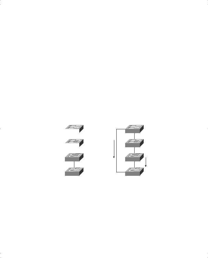
Rather than explain every nuance of RSTP convergence, one example will give you plenty of knowledge about the process. Figure 2-9 shows a network that explains RSTP convergence.
Figure 2-9 RSTP Convergence Example: Steps 1 and 2
Step 1 |
Step 2 |
|
|
Root |
|
SW1 |
|||
|
|||
|
|
Better |
|
SW2 |
|||
|
|
Root |
|
|
|
BPDU |
|
|
|
|
|
SW3
SW4
SW1 |
Root |
|
|
||
SW2 |
|
|
SW3 |
Old, No |
|
Longer as |
||
|
||
|
Good Root |
|
|
BPDU |
|
SW4 |
|
Figure 2-9 sets up the problem. On the left, in Step 1, the network has no redundancy. RSTP has placed all link-type point-to-point links in forwarding state. To add redundancy, the network engineer adds another link-type point-to-point link between SW1 and SW4, as shown on the right. So, RSTP convergence needs to occur.
The first step of convergence occurs when SW4 realizes that it is receiving a better BPDU than the one that entered from SW3. Because both the old and new root BPDUs advertise the same switch, SW1, the new, “better” BPDU coming over the direct link from SW1 must be better because of lower cost. Regardless of the reason, SW4 needs to transition to forwarding state on the new link to SW1, because it is now SW4’s root port.
54 Chapter 2: Spanning Tree Protocol
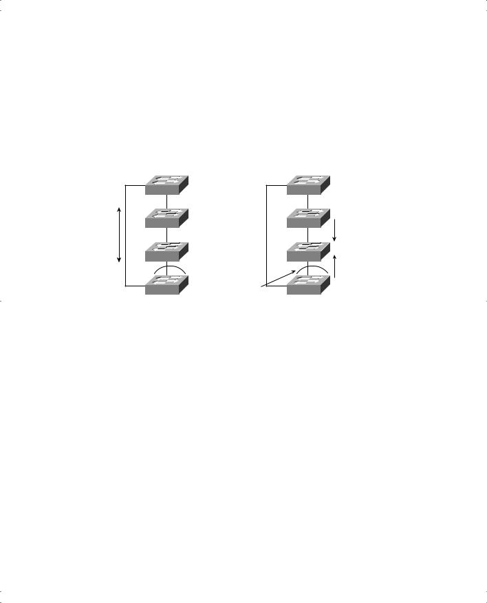
At this point, RSTP behavior diverges from STP. RSTP on SW4 now temporarily blocks all other link-type ports. By doing so, SW4 prevents the possibility of introducing loops. Then SW4 negotiates with its neighbor on the new root port, SW1, using RSTP Proposal and Agreement messages. As a result, SW4 and SW1 agree that they can each place their respective ends of the new link into forwarding state immediately. Figure 2-10 shows this third step.
Figure 2-10 RSTP Convergence Example: Steps 3 and 4
Step 3 |
Step 4 |
Negotiations
(Proposal and Agreement)
Results in
Immediate
Forwarding
State
SW1 |
Root |
|
|
SW2 |
|
SW3 |
Blocking — |
|
|
|
Prevents |
|
Loops While |
|
Negotiating |
SW4 |
|
|
SW1 |
Root |
|
|
|
|
SW2 |
Old, No |
|
Longer as |
|
|
|
|
|
|
Good Root |
|
|
BPDU |
|
SW3 |
Better |
|
|
Root |
|
|
BPDU |
SW4 Still |
SW4 |
|
Blocking! |
|
|
Why can SW1 and SW4 place their ends of the new link in forwarding state without causing a loop? Because SW4 blocks on all other link-type ports. In other words, it blocks on all other ports connected to other bridges or switches. That’s the key to understanding RSTP convergence. A switch knows it needs to change to a new root port. It blocks on all other links and then negotiates to bring the new root port to forwarding state. Essentially, SW4 tells SW1 to trust it and start forwarding, because SW4 promises to block all other ports until it is sure that it can move some of them back to forwarding state.
The process is not yet complete, however. The RSTP topology currently shows SW4 blocking, which in this example is not the final, best topology.
SW4 and SW3 repeat the same process that SW1 and SW4 just performed. In Step 4, SW4 still blocks, preventing loops. However, SW4 forwards the new root BPDU to SW3, so SW3 hears two BPDUs now. In this example, assume that SW3 thinks that the BPDU from SW4 is better than the one received from SW2—which makes SW3 repeat the same process that SW4 just performed. It follows this general flow from this point:
1.SW3 decides to change its root port based on this new BPDU from SW4.
2.SW3 blocks all other link-type ports. (RSTP calls this process synchronization.)
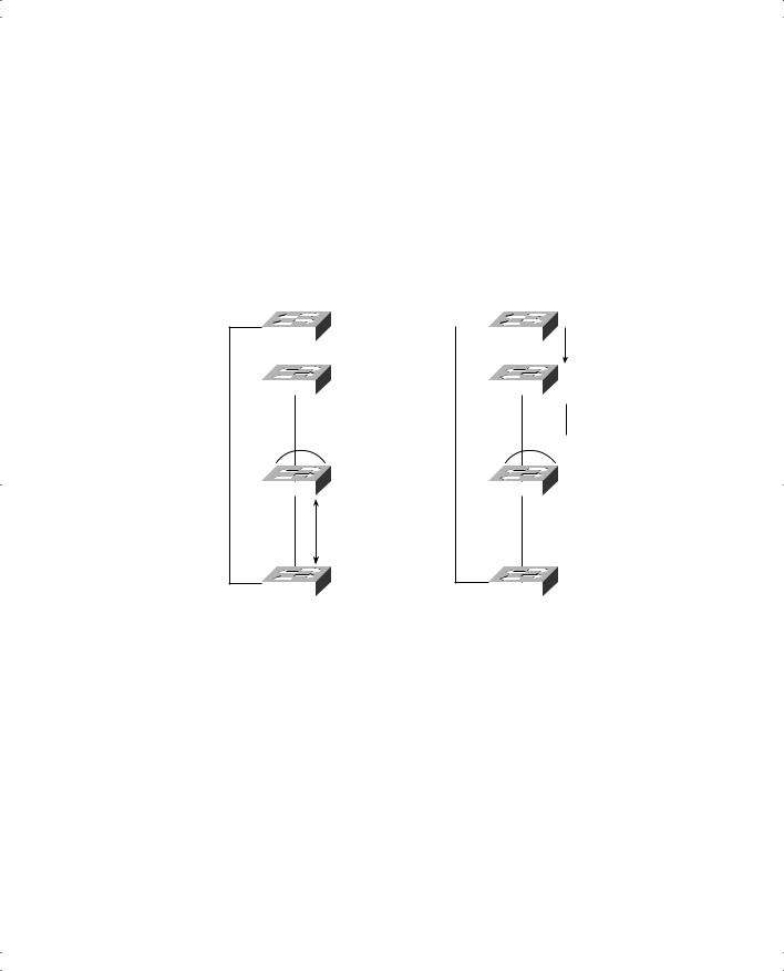
Rapid Spanning Tree (IEEE 802.1w) 55
3.SW3 and SW4 negotiate.
4.As a result of the negotiation, SW4 and SW3 can transition to forwarding on their interfaces on either end of the link-type point-to-point link.
5.SW3 maintains blocking state on all other link-type ports until the next step in the logic.
Figure 2-11 shows some of these steps in the Step 5 portion on the left and the resulting behavior in Step 6 on the right.
Figure 2-11 RSTP Convergence Example: Steps 5 and 6
Step 5 |
|
|
Step 6 |
||||
|
|
|
|
Root |
|
|
|
SW1 |
|
|
SW1 |
||||
|
|
|
|||||
|
|
|
|
|
|
|
|
SW2 |
|
|
|
SW2 |
|||
Blocking —
Prevents
Loops While
Negotiating
SW3 |
|
SW3 |
Negotiations (Proposal and Agreement)
Old BPDU Is Better than One from SW3
 Not as Good as BPDU from SW3
SW4 |
|
SW4 |
SW3 stills blocks on its upper interface at this point. Notice that SW2 is now receiving two BPDUs, but the same old BPDU it had been receiving all along is still the better BPDU. So SW2 takes no action. And RSTP is finished converging!
Although it took several pages to explain, the process in this example might take as little as 1 second. For the ICND exam, you should remember the terms relating to RSTP, as well as the concept that RSTP improves convergence time compared to STP.

56 Chapter 2: Spanning Tree Protocol
Spanning Tree Protocol Configuration
Cisco switches use STP by default. You can buy some switches, connect them with Ethernet cables in a redundant topology, and STP will ensure that no loops exist. And you never even to think about changing any of the settings!
You might want to change some of STP’s default settings. You might also want to use different settings for different virtual LANs (VLANs, which are covered in Chapter 3, “Virtual LANs and Trunking”). This section lists configuration and show commands for STP on the 2950 series switches. It also shows a simple example of how to examine STP parameters and change some common STP parameters.
Table 2-8 lists some of the 2950 commands relating to STP.
Table 2-8 Configuration and Operations Commands from This Chapter for 2950 Switches
Command |
Description |
|
|
spanning-tree vlan vlan-id root |
Global configuration command that changes |
|
this switch to the root switch. The switch’s |
|
priority is changed to the lower of either |
|
24,576 or 100 less than the priority of the |
|
current root bridge when the command was |
|
issued. |
|
|
spanning-tree vlan vlan-id {priority priority} |
Global configuration command that changes |
|
the bridge priority of this switch for the |
|
specified VLAN. |
|
|
spanning-tree cost cost |
Interface subcommand that changes the STP |
|
cost to the configured value. |
|
|
channel-group channel-group-number mode |
Interface subcommand that enables |
{auto | desirable | on} |
EtherChannel on the interface. |
|
|
show spanning-tree |
EXEC command that lists details about the |
|
state of STP on the switch, including the |
|
state of each port. |
|
|
show spanning-tree interface interface-id |
EXEC command that lists STP information |
|
only for the specified port. |
|
|
show spanning-tree vlan vlan-id |
EXEC command that lists STP information |
|
for the specified VLAN. |
|
|
debug spanning-tree |
EXEC command that causes the switch to |
|
provide informational messages about |
|
changes in the STP topology. |
|
|
show etherchannel [channel-group-number] |
EXEC command that lists information about |
{brief | detail | port | port-channel | summary} |
the state of EtherChannels on this switch. |
|
|