

238 Chapter 7: Advanced Routing Protocol Topics
Classful and Classless Routing
IP routing—the actual process of forwarding IP packets—can be considered either classful or classless. As mentioned in the preceding section, routing protocols also are considered either classful or classless. Classless routing protocols ignore Class A, B, and C rules, because they have much better information—the actual subnet masks sent with routing updates.
Similarly, IP routing is classless when the process of forwarding packets ignores class rules, and it is classful when routing must consider class rules when making a decision. However, the concepts behind classless and classful routing are totally independent of the routing protocol used and how it is configured. In fact, a router can use only static routes, and the concepts of classless and classful routing would still apply.
The choice of whether a router uses classful or classless routing determines how that router uses its default route. So, to fully understand what classless and classful routing really mean, you must first understand a little more about default routes. When a router needs to route a packet, and there is no route matching that packet’s destination in the routing table, the router discards the packet. Routers that have a default route can consider that packets that do not match a more specific route at least match the default route, so the packet is forwarded according to the default route, as opposed to being discarded. To appreciate the meaning of the terms classless routing and classful routing, you must first take a closer look at default routes in Cisco routers.
Default Routes
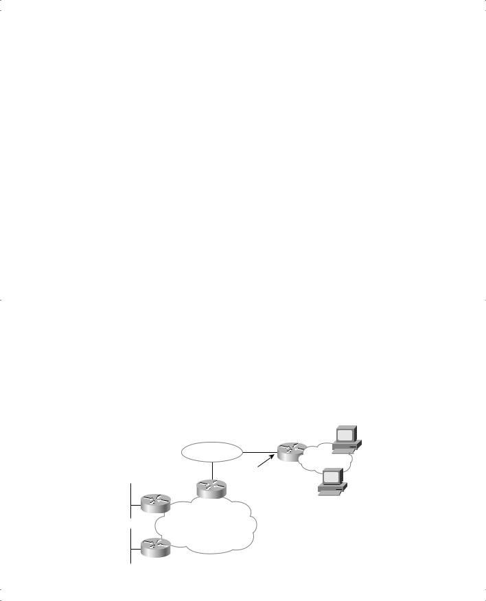
Default routes work best when only one path exists to a part of the network. In Figure 7-5, R1, R2, and R3 are connected to the rest of the network only through R1’s Token Ring interface. All three routers can forward packets to the rest of the network as long as the packets get to R1, which forwards them to Dist1.
Figure 7-5 Sample Network Using a Default Route
168.13.200.1
|
Dist1 |
|
168.13.1.0/24 |
|
Rest of Net |
|
168.13.1.101 |
168.13.2.0/24 |
R1 |
|
|
|
10.1.1.1 |
R2 |
168.13.100.1 |
168.13.100.0/24 |
Frame
Relay
168.13.3.0/24
R3
Classless Routing Protocols and Classless Routing 239
By coding a default route on R1 that points to router Dist1 in Figure 7-5, and by having R1 advertise the default to R2 and R3, default routing can be accomplished. (Chapter 5, “RIP, IGRP, and Static Route Concepts and Configuration,” covers the basics of how to configure static routes.) R1, R2, and R3 should not need specific routes to the subnets to the right of router Dist1. Examples 7-9 and 7-10, along with Figure 7-5, show an example of a default route on R1.
Example 7-9 R1 Static Default Route Configuration and Routing Table
R1(config)#ip route 0.0.0.0 0.0.0.0 168.13.1.101
R1#show ip route
Codes: C - connected, S - static, I - IGRP, R - RIP, M - mobile, B - BGP
D - EIGRP, EX - EIGRP external, O - OSPF, IA - OSPF inter area
N1 - OSPF NSSA external type 1, N2 - OSPF NSSA external type 2
E1 - OSPF external type 1, E2 - OSPF external type 2, E - EGP
i - IS-IS, L1 - IS-IS level-1, L2 - IS-IS level-2, ia - IS-IS inter area * - candidate default, U - per-user static route, o - ODR
P - periodic downloaded static route
Gateway of last resort is 168.13.1.101 to network 0.0.0.0
168.13.0.0/24 is subnetted, 4 subnets
C168.13.1.0 is directly connected, TokenRing0
R168.13.3.0 [120/1] via 168.13.100.3, 00:00:05, Serial0.1
R168.13.2.0 [120/1] via 168.13.100.2, 00:00:21, Serial0.1 C 168.13.100.0 is directly connected, Serial0.1
S* |
0.0.0.0/0 [1/0] via 168.13.1.101 |
R1# |
|
Example 7-10 R3: Nuances of the Successful Use of the Static Route on R1
R3#show ip route
Codes: C - connected, S - static, I - IGRP, R - RIP, M - mobile, B - BGP
D - EIGRP, EX - EIGRP external, O - OSPF, IA - OSPF inter area
N1 - OSPF NSSA external type 1, N2 - OSPF NSSA external type 2
E1 - OSPF external type 1, E2 - OSPF external type 2, E - EGP
i - IS-IS, L1 - IS-IS level-1, L2 - IS-IS level-2, ia - IS-IS inter area * - candidate default, U - per-user static route, o - ODR
P - periodic downloaded static route
Gateway of last resort is 168.13.100.1 to network 0.0.0.0
168.13.0.0/24 is subnetted, 4 subnets
R168.13.1.0 [120/1] via 168.13.100.1, 00:00:13, Serial0.1 C 168.13.3.0 is directly connected, Ethernet0
R168.13.2.0 [120/1] via 168.13.100.2, 00:00:06, Serial0.1 C 168.13.100.0 is directly connected, Serial0.1

240 Chapter 7: Advanced Routing Protocol Topics
R1 defines the default route with a static ip route command, with destination 0.0.0.0, mask 0.0.0.0. This route matches all destinations by convention. R1 advertises this default route to R2 and R3, as shown in the output of the show ip route command on R3 in Example 7-10.
Different routing protocols advertise default routes in a couple of different ways. As an example, this chapter covers how RIP handles the default in this network. R1 lists a static route to 0.0.0.0, mask 0.0.0.0, with next hop 168.13.1.101—essentially, the same information that was entered in the ip route 0.0.0.0 0.0.0.0 168.13.1.101 global configuration command. RIP advertises this default to R2 and R3, which, instead of listing 0.0.0.0 as a network in their routing tables, list the phrase that begins “Gateway of last resort”. When no other route is matched, the gateway of last resort can be used to forward the packet. In other words, it is the default route.
Another style of configuration for the default route uses the ip default-network command.
This command is used most typically when you want to reach other Class A, B, or C networks by default but all the subnets of your own network are expected to be in your own routing tables. For example, imagine that the cloud next to Dist1 in Figure 7-5 has subnets of network 10.0.0.0 in it as well as other networks. (Dist1 could be an ISP router.) Dist1 already advertises a route to network 10.0.0.0 to R1, so R1 decides to use the same routing information for that route as its default route. To do that instead of using the ip route 0.0.0.0 0.0.0.0 168.13.1.101 command, the ip default-network 10.0.0.0 command is used on R1. R1 uses its route to network 10.0.0.0 as its default and advertises this route as a default route to other routers. Examples 7-11 and 7-12 show several details about R1 and R3.
Example 7-11 R1’s Use of the ip default-network Command
R1#configure terminal
R1(config)#ip default-network 10.0.0.0
R1(config)#exit
R1#show ip route
Codes: C - connected, S - static, I - IGRP, R - RIP, M - mobile, B - BGP
D - EIGRP, EX - EIGRP external, O - OSPF, IA - OSPF inter area
N1 - OSPF NSSA external type 1, N2 - OSPF NSSA external type 2
E1 - OSPF external type 1, E2 - OSPF external type 2, E - EGP
i - IS-IS, L1 - IS-IS level-1, L2 - IS-IS level-2, ia - IS-IS inter area * - candidate default, U - per-user static route, o - ODR
P - periodic downloaded static route
Gateway of last resort is 168.13.1.101 to network 10.0.0.0
168.13.0.0/24 is subnetted, 5 subnets
R168.13.200.0 [120/1] via 168.13.1.101, 00:00:12, TokenRing0 C 168.13.1.0 is directly connected, TokenRing0
R168.13.3.0 [120/1] via 168.13.100.3, 00:00:00, Serial0.1
R168.13.2.0 [120/1] via 168.13.100.2, 00:00:00, Serial0.1
C168.13.100.0 is directly connected, Serial0.1
R* |
10.0.0.0/8 [120/1] via 168.13.1.101, 00:00:12, TokenRing0 |
R1# |
|

Classless Routing Protocols and Classless Routing 241
Example 7-12 R3 Routing Table and trace Command Samples
R3#show ip route
Codes: C - connected, S - static, I - IGRP, R - RIP, M - mobile, B - BGP
D - EIGRP, EX - EIGRP external, O - OSPF, IA - OSPF inter area
N1 - OSPF NSSA external type 1, N2 - OSPF NSSA external type 2
E1 - OSPF external type 1, E2 - OSPF external type 2, E - EGP
i - IS-IS, L1 - IS-IS level-1, L2 - IS-IS level-2, ia - IS-IS inter area * - candidate default, U - per-user static route, o - ODR
P - periodic downloaded static route
Gateway of last resort is 168.13.100.1 to network 0.0.0.0
168.13.0.0/24 is subnetted, 5 subnets
R168.13.200.0 [120/2] via 168.13.100.1, 00:00:26, Serial0.1
R168.13.1.0 [120/1] via 168.13.100.1, 00:00:26, Serial0.1
C168.13.3.0 is directly connected, Ethernet0
R168.13.2.0 [120/1] via 168.13.100.2, 00:00:18, Serial0.1 C 168.13.100.0 is directly connected, Serial0.1
R10.0.0.0/8 [120/2] via 168.13.100.1, 00:00:26, Serial0.1
R* 0.0.0.0/0 [120/2] via 168.13.100.1, 00:00:26, Serial0.1
R3#trace 168.13.222.2
Type escape sequence to abort.
Tracing the route to 168.13.222.2
1 168.13.100.1 68 msec 56 msec 52 msec
2 168.13.1.101 52 msec 56 msec 52 msec R3#trace 10.1.1.1
Type escape sequence to abort.
Tracing the route to 10.1.1.1
1 168.13.100.1 68 msec 56 msec 52 msec
2 168.13.1.101 48 msec 56 msec 52 msec R3#
Both R1 and R3 have default routes, but they are shown differently in their respective routing tables. R1 shows a route to network 10.0.0.0 with an *, meaning that it is a candidate to be the default route. In R3, 0.0.0.0 shows up in the routing table as the candidate default route. R3 shows this information differently because RIP advertises default routes using network number 0.0.0.0. If IGRP or EIGRP were in use, there would be no route to 0.0.0.0 on R3, and network 10.0.0.0 would be the candidate default route. That’s because IGRP and EIGRP would flag 10.0.0.0 as a candidate default route in their routing updates rather than advertise the special case of 0.0.0.0. The RIP protocol simply uses a different convention for how to advertise a default route.