


102 Chapter 4: IP Addressing and Subnetting
Foundation Topics
This chapter begins with a brief review of IP addressing and subnetting. Following that, the text takes a thorough look at several types of IP addressing questions and the math you can use to find the answers.
IP Addressing Review
Before we look at the math behind IP addressing, a quick review will be helpful.
Many different Class A, B, and C networks exist. Table 4-2 summarizes the possible network numbers, the total number of each type, and the number of hosts in each Class A, B, and C network.
NOTE In the table, the Valid Network Numbers row shows actual network numbers. There are several reserved cases. For example, network 0.0.0.0 (originally defined for use as a broadcast address) and network 127.0.0.0 (still available for use as the loopback address) are reserved. Networks 128.0.0.0, 191.255.0.0, 192.0.0.0, and 223.255.255.0 also are reserved.
Table 4-2 List of All Possible Valid Network Numbers
|
Class A |
Class B |
Class C |
|
|
|
|
First Octet Range |
1 to 126 |
128 to 191 |
192 to 223 |
|
|
|
|
Valid Network Numbers |
1.0.0.0 to |
128.1.0.0 to |
192.0.1.0 to |
|
126.0.0.0 |
191.254.0.0 |
223.255.254.0 |
|
|
|
|
Number of Networks in This Class |
27 – 2 |
214 – 2 |
221 – 2 |
Number of Hosts Per Network |
224 – 2 |
216 – 2 |
28 – 2 |
Size of Network Part of Address (bytes) |
1 |
2 |
3 |
|
|
|
|
Size of Host Part of Address (bytes) |
3 |
2 |
1 |
|
|
|
|
Without subnetting, a different IP network must be used for each physical network. For example, Figure 4-1 shows three IP addresses, each from a different network. One address is in a Class A network, one is in a Class B network, and one is in a Class C network.

IP Addressing Review 103
Figure 4-1 Class A, B, and C IP Addresses and Their Formats
Class A |
Network |
|
Host (24) |
|
|
|
||
(8) |
|
|
|
|
|
|||
|
|
|
|
|
|
|
|
|
|
8 |
. |
1 |
. |
4 |
. |
5 |
|
|
|
|
|
|
||||
Class B |
Network (16) |
|
Host (16) |
|||||
|
|
|
|
|
|
|
|
|
|
130 |
. |
4 |
. |
100 |
. |
1 |
|
Class C |
|
|
|
|
|
|
|
|
|
|
|
|
|
|
|||
|
Network (24) |
|
|
|
Host (8) |
|||
|
|
|
|
|
|
|
|
|
|
199 |
. |
1 |
. |
1 |
|
. |
1 |
|
|
|
|
|
|
|
|
|
By definition, an IP address that begins with 8 in the first octet is in a Class A network, so the network part of the address is the first byte, or first octet. An address that begins with 130 is in a Class B network. By definition, Class B addresses have a 2-byte network part, as shown. Finally, any address that begins with 199 is in a Class C network, which has a 3-byte network part. Also by definition, a Class A address has a 3-byte host part, Class B has a 2- byte host part, and Class C has a 1-byte host part.
Humans can simply remember the numbers in Table 4-2 and the concepts in Figure 4-1 and then quickly determine the network and host part of an IP address. Computers, however, use a mask to define the size of the network and the host parts of an address. The logic behind the mask results in the same conventions of Class A, B, and C networks that you already know, but the computer can deal with it better as a binary math problem. The mask is a 32bit binary number, usually written in dotted-decimal format. The purpose of the mask is to define the structure of an IP address. In short, the mask defines the size of the host parts of an IP address, representing the host part of the IP address with binary 0s in the mask. The Class A mask has its last 24 bits as binary 0, which means that the last three octets of the mask are 0s. Table 4-3 summarizes the default masks and reflects the sizes of the two parts of an IP address.
Table 4-3 Class A, B, and C Networks: Network and Host Parts and Default Masks
Class of |
Size of Network Part of |
Size of Host Part of |
Default Mask for Each |
Address |
Address in Bits |
Address in Bits |
Class of Network |
|
|
|
|
A |
8 |
24 |
255.0.0.0 |
|
|
|
|
B |
16 |
16 |
255.255.0.0 |
|
|
|
|
C |
24 |
8 |
255.255.255.0 |
|
|
|
|

104 Chapter 4: IP Addressing and Subnetting
IP Subnetting
IP subnetting creates vastly larger numbers of smaller groups of IP addresses compared with simply using Class A, B, and C conventions. The Class A, B, and C rules still exist, but now a single Class A, B, or C network can be subdivided into many smaller groups. Subnetting treats a subdivision of a single Class A, B, or C network as if it were a network itself. By doing so, a single Class A, B, or C network can be subdivided into many nonoverlapping subnets.
Figures 4-2 and 4-3 show the basic differences between a network that does not use subnetting and one that does. First, look at Figure 4-2, which uses six different IP networks.
Figure 4-2 Network Topology Using Six IP Networks
|
Ray 150.1.0.0 |
|
150.2.0.0 Hannah |
||||||||||||
|
|
|
|
|
|
|
A |
B |
|
|
|
|
|
|
|
|
|
|
|
|
|
|
|
|
|
|
|
||||
|
|
|
|
|
|
|
|
|
|
|
|
|
|
|
|
|
|
|
|
|
|
|
|
|
|
|
|
|
|
|
|
|
|
|
|
|
|
|
|
|
|
|
|
|
|
|
|
|
|
|
|
|
|
|
|
|
|
|
|
|
|
|
|
|
|
|
|
|
|
|
|
|
|
|
|
|
|
|
|
|
|
|
|
|
|
|
|
|
|
|
|
|
|
|
|
|
|
|
|
|
|
|
|
|
|
|
|
|
|
|
|
|
|
|
|
|
|
|
|
|
|
|
|
|
|
|
|
|
|
|
|
|
|
|
|
|
|
|
|
|
|
|
|
Fay |
Jessie |
Frame
Relay 150.5.0.0
D
C 
150.6.0.0
150.3.0.0
150.4.0.0
Vinnie
Kris Wendell
The design shown in Figure 4-2 requires six groups, each of which is a Class B network. The four LANs each use a single Class B network. In other words, the LANs attached to Routers A, B, C, and D are each a separate network. Additionally, the two serial interfaces comprising the point-to-point serial link between Routers C and D use the same network, because these two interfaces are not separated by a router. Finally, the three router interfaces comprising
IP Addressing Review 105
the Frame Relay network with Routers A, B, and C are not separated by an IP router and would comprise the sixth network.
NOTE Other Frame Relay IP addressing options would require one or two more IP network numbers for this physical network.
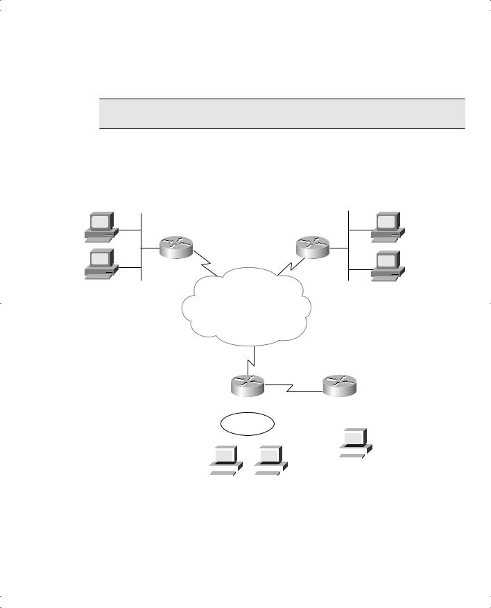
As in Figure 4-2, the design shown in Figure 4-3 requires six groups. Unlike Figure 4-2, Figure 4-3 uses six subnets, each of which is a subnet of a single Class B network.
Figure 4-3 Same Network Topology Using One IP Network with Six Subnets
Ray 150.150.1.0 |
150.150.2.0 |
Hannah |
A |
B |
150.150.2.1 |
|
|
150.150.2.2 |
Fay |
Frame |
Jessie |
|
|
|
|
Relay |
|
|
150.150.5.0 |
|
|
|
|
|
|
|
|
|
|
|
|
|
|
D |
|||||||
|
C |
150.150.6.0 |
|
|
|
|
|
|
|
|||||||||||
|
|
|
|
|
|
|
|
|
|
|
|
|
|
|
|
|
||||
|
|
|
|
|
|
|
150.150.3.0 |
|||||||||||||
|
|
|
|
|
|
|
|
|||||||||||||
|
|
|
|
|
|
|
|
|
|
|
|
|
|
|||||||
150.150.4.0 |
|
|
|
|
|
|
|
|
|
|
|
|
||||||||
|
|
|
|
|
|
|
|
|
|
|
|
|
|
|
|
|
|
|
|
|
|
|
|
|
|
|
|
|
|
|
|
|
|
|
|
|
|
|
|
|
|
|
|
|
|
|
|
|
|
|
|
|
|
|
|
|
|
|
|
|
|
|
|
|
|
|
|
|
|
|
|
|
|
|
|
|
|
|
|
|
|
|
|
|
|
|
|
|
|
|
|
|
|
|
|
|
|
|
|
|
|
|
||
|
|
|
|
|
|
|
|
|
|
|
|
|
|
Vinnie |
||||||
|
|
|
|
|
|
|
|
|||||||||||||
|
|
|
|
|
|
|
|
|
|
|
|
|
|
|
|
|
|
|
|
|
|
|
|
|
|
|
|
|
|
|
|
|
|
|
|
|
|
|
|
|
|
|
Kris |
|
|
Wendell |
||||||||||||||||
150.150.4.2
This design subnets Class B network 150.150.0.0. The IP network designer has chosen a mask of 255.255.255.0, the last octet of which implies 8 host bits. Because it is a Class B network, there are 16 network bits. Therefore, there are 8 subnet bits, which happen to be bits 17 through 24—in other words, the third octet.