


288 Chapter 8: Advanced TCP/IP Topics
Table 8-10 summarizes some features of TFTP and FTP.
Table 8-10 Comparison of FTP and TFTP
FTP |
TFTP |
|
|
Uses TCP |
Uses UDP |
|
|
Uses robust control commands |
Uses simple control commands |
|
|
Sends data over a TCP connection separate from |
Uses no connections because of UDP |
control commands |
|
|
|
Requires more memory and programming effort |
Requires less memory and |
|
programming effort |
|
|
MTU and Fragmentation
TCP/IP defines a maximum length for an IP packet. The term used to describe that maximum length is maximum transmission unit (MTU).
The MTU varies based on configuration and the interface’s characteristics. By default, a computer calculates an interface’s MTU based on the maximum size of the data portion of the data-link frame (where the packet is placed). For instance, the default MTU value on Ethernet interfaces is 1500.
Routers, like any IP host, cannot forward a packet out an interface if the packet is longer than the MTU. If a router’s interface MTU is smaller than a packet that must be forwarded, the router fragments the packet into smaller packets. Fragmentation is the process of breaking the packet into smaller packets, each of which is less than or equal to the MTU value.
Figure 8-18 shows an example of fragmentation in a network where the MTU on the serial link has been lowered to 1000 bytes via configuration.
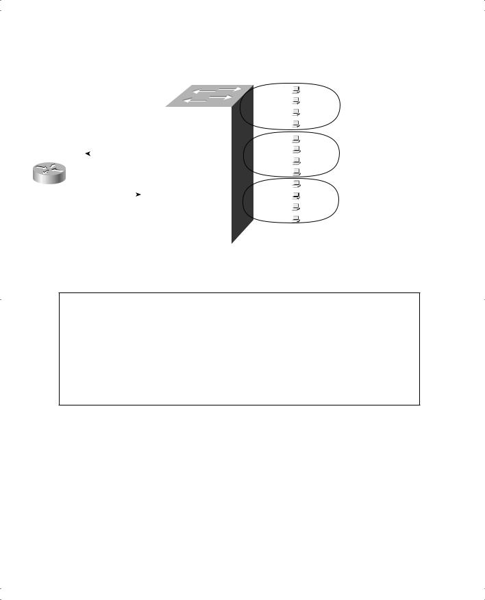
Figure 8-18 IP Fragmentation
|
|
Koufax |
|
|
|
|
|
|
|
Boston |
|
Clemens |
|||||||||||||
|
|
|
|
|
|
|
|
|
LA |
|
|
|
|
|
|
|
|
|
|||||||
|
|
|
|
|
|
|
|
|
|
|
|
|
|
|
|
|
|
|
|
|
|
|
|
|
|
|
|
|
|
|
|
|
|
|
|
|
|
|
|
|
|
|
|
|
|
|
|
|
|
|
|
|
|
|
|
|
|
|
|
|
|
|
|
MTU 1000 |
|
|
|
|
|
|
|
||||||
|
|
|
|
|
|
|
|
|
|
|
|
|
|
|
|
|
|
|
|||||||
|
|
|
|
|
|
|
|
|
|
|
|
|
|
|
|
|
|||||||||
|
|
|
|
|
|
|
|
|
|
|
|
|
|
|
|
|
|
|
|
|
|
|
|
|
|
|
|
|
|
|
|
|
|
|
|
|
|
|
|
|
|
|
|
|
|
|
|
|
|||
|
|
|
|
|
|
|
|
|
|
|
|
|
|
|
|
|
|
|
|
|
|
|
|
|
|
|
|
Ethernet |
IP (1500) |
|
|
|
|
|
|
|
Ethernet |
IP (750) |
|||||||||||||
|
|
|
|
|
|
|
|
|
|
|
|
|
|
|
|
|
|
|
|
|
|
|
|
|
|
|
|
|
|
|
|
|
|
|
|
|
|
|
|
|
|
|
|
|
|||||||
|
|
|
|
|
|
|
|
|
|
|
|
|
|
|
|
|
|
|
|
|
|
|
|
|
|
|
|
|
|
|
|
|
|
|
|
|
|
|
|
|
|
|
Ethernet |
IP (750) |
|||||||
|
|
|
|
|
|
|
|
|
|
|
|
HDLC |
IP (750) |
|
|
|
|
|
|
|
|
|
|||
|
|
|
|
|
|
|
|
|
|
|
|
|
|
|
|
|
|
||||||||
|
|
|
|
|
|
|
|
|
|
|
|
|
|
|
|
|
|
|
|
|
|
|
|||
|
|
|
|
|
|
|
|
|
|
|
|
|
|
|
|
|
|
|
|
|
|||||
|
|
|
|
|
|
|
|
|
|
|
|
|
|
|
|
|
|
|
|
|
|
|
|
|
|
|
|
|
|
|
|
|
|
|
|
|
|
HDLC |
IP (750) |
|
|
|
|
|
|
|
|
|
|
|
|
|
|
|
|
|
|
|
|
|
|
|
|
|
|
|
|
|
|
|
|
|
|
|
|
|
|
Miscellaneous TCP/IP Topics 289
As Figure 8-18 illustrates, Koufax sends a 1500-byte packet toward Router LA. LA removes the Ethernet header but cannot forward the packet as is, because it is 1500 bytes and the HDLC link supports an MTU of only 1000. So LA fragments the original packet into two packets, each 750 bytes in length. (The router does the math required to figure out the minimum number of fragments [2 in this case] and breaks the original packet into equallength packets. Because of this, any other routers the packets might go through are less likely to need to perform fragmentation.) After forwarding the two packets, Boston receives the packets and forwards them without reassembling them. Reassembly is done by the endpoint host, which in this case is Clemens.
The IP header contains fields useful for reassembling the fragments into the original packet. The
IP header includes an ID value that is the same in each fragmented packet, as well as an offset value that defines which part of the original packet is held in each fragment. Fragmented packets arriving out of order can be identified as a part of the same original packet and can be reassembled in the correct order using the offset field in each fragment.
Two configuration commands can be used to change the IP MTU size on an interface: the mtu interface subcommand and the ip mtu interface subcommand. The mtu command sets the MTU for all Layer 3 protocols; unless there is a need to vary the setting per Layer 3 protocol, this command is preferred. If a different setting is desired for IP, the ip mtu command sets the value used for IP. If both are configured on an interface, the IP MTU setting takes precedence on that interface. However, if the mtu command is configured after ip mtu is configured, the ip mtu value is reset to the same value as that of the mtu command. Care must be taken when changing these values.
ISL and 802.1Q Configuration on Routers
As discussed in Chapter 3, “Virtual LANs and Trunking,” VLAN trunking can be used between two switches and between a switch and a router. Trunking between a switch and a router reduces the number of router interfaces needed to route between the various VLANs. Instead of a single physical interface on the router for each VLAN on the switch, one physical interface can be used, and the router can still route packets between the various VLANs.
Figure 8-19 shows a router with a single Fast Ethernet interface and a single connection to a switch. Either ISL or 802.1Q trunking can be used, with only small differences in the configuration for each. For frames that contain packets that the router routes between the two virtual LANs (VLANs), the incoming frame is tagged by the switch with one VLAN ID, and the outgoing frame is tagged by the router with the other VLAN ID. Example 8-6 shows the router configuration required to support ISL encapsulation and forwarding between these VLANs.
290 Chapter 8: Advanced TCP/IP Topics
Figure 8-19 Router Forwarding Between VLANs
|
|
|
|
|
|
|
|
|
|
|
|
|
Dino |
VLAN 1 |
|
|
|
|
|
|
|
|
|
|
|
|
|
||
|
|
|
|
|
|
|
|
|
|
|
|
|
|
|
|
|
|
|
|
|
|
|
|
|
|
|
|
|
|
|
|
|
|
|
|
|
|
|
|
|
|
|
Fred |
IP Subnet 10.1.1.0/24 |
|
|
|
|
|
|
|
|
|
|
|
|
|
||
|
|
|
|
|
|
|
|
|
|
|
|
|
|
|
|
|
|
|
|
|
|
|
|
|
|
|
|
|
|
|
|
|
|
|
|
|
|
|
|
|
|
|
|
|
|
|
|
|
|
|
|
|
|
|
|
|
|
|
|
|
|
|
|
|
|
|
|
|
|
|
|
Wilma |
VLAN 2 |
|
|
|
|
|
|
|
|
|
|
|
|
|
|||
|
|
|
|
|
|
|
|
|
|
|
|
|||
|
|
|
|
|
|
|
|
|
|
|
||||
|
|
|
|
|
|
|
|
|
|
|
||||
|
|
|
|
|
|
|
|
|
|
|
|
|
|
IP Subnet 10.1.2.0/24 |
|
|
|
|
|
|
|
|
|
|
|
|
|
|
|
|
|
|
|
|
|
|
|
|
|
|
|
|
|
|
FA0 |
VLAN1 |
Frame |
|
|
|
|
|
|
|
|
Barney |
|
||
|
|
|
|
|
|
|
|
|
||||||
|
|
|
|
|
|
|
|
|
|
|
|
|
||
|
|
|
|
|
|
|
|
|
|
|
|
|
|
|
|
|
|
|
|
|
|
|
|
|
|
|
|
|
|
|
|
|
|
|
|
|
|
|
|
|
|
|
|
|
|
VLAN2 |
Frame |
|
|
|
|
|
|
|
|
VLAN 3 |
|||
|
|
|
|
|
||||||||||
|
|
|
|
|
|
|
|
|||||||
|
|
|
|
|
|
|
|
|||||||
|
|
|
|
|
|
|
|
|
|
|
|
|
|
|
|
|
|
|
|
|
|
|
|
|
|
|
|
|
|
|
|
|
|
|
|
|
|
|
|
|
|
|
|
IP Subnet 10.1.3.0/24 |
|
|
|
|
|
|
|
|
|
|
|
|
|
|
|
|
|
|
|
|
|
|
|
|
|
|
|
|
|
|
|
|
|
|
|
|
|
|
|
|
|
|
|
|
|
|
|
|
|
|
|
|
|
|
|
|
|
|
|
|
|
|
|
|
|
|
|
|
|
|
|
|
|
|
|
|
|
|
|
|
|
|
|
|
|
|
|
|
|
|
|
|
|
|
|
|
|
|
|
|
|
|
|
|
|
|
|
|
|
|
|
|
|
|
|
|
|
|
|
|
Example 8-6 Router Configuration for the ISL Encapsulation Shown in Figure 8-19
interface fastethernet 0.1
ip address 10.1.1.1 255.255.255.0 encapsulation isl 1
!
interface fastethernet 0.2
ip address 10.1.2.1 255.255.255.0 encapsulation isl 2
!
interface fastethernet 0.3
ip address 10.1.3.1 255.255.255.0 encapsulation isl 3
Example 8-6 shows the configuration for three subinterfaces of the FastEthernet interface on the router. Each is assigned an IP address because the interface is actually a part of three VLANs, implying three IP subnets. So, instead of three physical interfaces, each attached to a different subnet and broadcast domain, there is one physical router interface with three logical subinterfaces, each attached to a different subnet and broadcast domain. The encapsulation command numbers the VLANs, which must match the configuration for VLAN IDs in the switch.

Miscellaneous TCP/IP Topics 291
This example uses subinterface numbers that match the VLAN ID on each subinterface. There is no requirement that the numbers match, but most people choose to make them match, just to make the configuration more obvious. In other words, the VLAN IDs may be 1, 2, and 3, but the subinterface numbers could have been 4, 5 and 6, because the subinterface numbers are just used internally by the router.
Example 8-7 shows the same network, but this time with 802.1Q used instead of ISL. IEEE 802.1Q has a concept called the native VLAN, which is a special VLAN on each trunk for which no 802.1Q headers are added to the frames. By default, VLAN 1 is the native VLAN. Example 8-7 shows the difference in configuration.
Example 8-7 Router Configuration for the 802.1Q Encapsulation Shown in Figure 8-19
interface fastethernet 0
ip address 10.1.1.1 255.255.255.0
!
interface fastethernet 0.2
ip address 10.1.2.1 255.255.255.0 encapsulation dot1q 2
!
interface fastethernet 0.3
ip address 10.1.3.1 255.255.255.0 encapsulation dot1q 3
The router IP address in the subnet of the 802.1Q native VLAN is configured on the physical interface instead of the subinterface. Note that the keyword for the encapsulation is dot1q. Also note that for the native VLAN, VLAN 1 in this case, the encapsulation command should not be used, or the router will encapsulate frames in an 802.1Q header. The rest of the configuration is identical to ISL. Also, there is no need to match the subinterface numbers and VLAN numbers. It’s just a good practice to help you keep track of things.