


462 Chapter 13: Final Preparation
Final Lab Scenarios
The current CCNA exams include simulated lab questions. The best way to prepare for these is to work with live networks using Cisco routers and switches. You should also make sure to do all the questions in the testing engine on the acocompanying CD, as it contains a large number of simulated lab questions. You can also use the NetSim network simulator on the CD, or rent time via online labs.
Regardless of how much time and effort you spend with hands-on practice, the following lab scenario can help you with your final preparation if you simply read through the scenarios. Throughout this book, the portions that covered how to do something on a switch or router focused on the specific topics covered in that chapter. The scenarios in this chapter touch on many of the topics in this book that are in some way related to configuration or operating a router or switch. You can use these scenarios as part of your final exam preparation strategy.
If you have enough time, review all the parts of each scenario, and try to perform all the tasks outlined in Parts A, B, and C. However, if you have limited time, you might want to review the problem statements and then the answers for each of the three parts. At least you will get a good review of some of the more important commands that could be on the exam.
If you are reading this chapter as your final review before taking the exam, let me take this opportunity to wish you success. Hopefully you will be relaxed and confident for your exam—and hopefully this book has helped you build your knowledge and confidence.
Scenario 1
Scenario 1 uses a Frame Relay network with three routers and a full mesh of virtual circuits. Some planning exercises begin the scenario (Part A), followed by configuration (Part B). Finally, a series of questions, some based on show and debug command output, finish the scenario (Part C).
Scenario 1, Part A: Planning
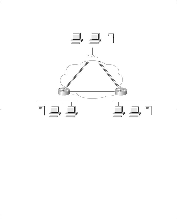
Your job is to deploy a new network with three sites, as shown in Figure 13-1. The decision to use Frame Relay has already been made, and the products have been chosen. For Part A of this scenario, perform the following task:
■Subnet planning has been completed. Before implementation, you are responsible for providing a list for the local LAN administrators defining the IP addresses they can assign to hosts. Using Table 13-1, derive the subnet numbers and broadcast addresses, and define the range of valid IP addresses. A static mask of 255.255.255.192 is used on all subnets.
 R1
R1
464 Chapter 13: Final Preparation
Frame Relay interfaces are treated as a single network. Table 13-2 provides the answers to this question.
Table 13-2 Scenario 1, Part A: IP Subnet Network Planning Chart
Router |
|
|
Subnet |
Range of Valid |
|
Interface |
IP Address |
Subnet Number |
Broadcast Address |
Addresses |
|
|
|
|
|
|
|
R1 |
E0 |
168.11.11.101 |
168.11.11.64 |
168.11.11.127 |
65 to 126 in last octet |
|
|
|
|
|
|
R2 |
E0 |
168.11.12.102 |
168.11.12.64 |
168.11.12.127 |
65 to 126 in last octet |
|
|
|
|
|
|
R3 |
E0 |
168.11.13.103 |
168.11.13.64 |
168.11.13.127 |
65 to 126 in last octet |
|
|
|
|
|
|
R1 |
S0 |
168.11.123.201 |
168.11.123.192 |
168.11.123.255 |
193 to 254 in last octet |
|
|
|
|
|
|
R2 |
S0 |
168.11.123.202 |
168.11.123.192 |
168.11.123.255 |
193 to 254 in last octet |
|
|
|
|
|
|
R3 |
S0 |
168.11.123.203 |
168.11.123.192 |
168.11.123.255 |
193 to 254 in last octet |
|
|
|
|
|
|
Scenario 1, Part B: Configuration
The next step in your job is to deploy the network designed in Scenario 1, Part A. Use the solutions to Scenario 1, Part A to help you identify IP addresses to be used. Perform the following tasks:
Step 1 Configure IP to be routed. Use IP IGRP as the routing protocol. Use IGRP autonomous system number 1.
Step 2 Configure Frame Relay without the use of subinterfaces. R1’s attached switch uses LMI type ANSI. Cisco encapsulation should be used for all routers.
Step 3 Assume that, after you installed the network, you were forced to disable IP IGRP on R2. Define the required IP static routes to allow hosts on all three Ethernets to communicate. (This is unlikely to happen in real life; it’s just an excuse to review IP static routes!)
Step 4 Assume that, after you installed the network, you were forced to disable
Inverse ARP on R2. Define static mappings as necessary for all hosts to communicate.
Solutions to Scenario 1, Part B: Configuration
Examples 13-1, 13-2, and 13-3 show the configurations for Tasks 1 and 2.
Example 13-1 R1 Configuration
interface serial0
encapsulation frame-relay
ip address 168.11.123.201 255.255.255.192


466 Chapter 13: Final Preparation
Example 13-4 Static Routes (Continued)
R2(config)#ip route 168.11.13.64 255.255.255.192 168.11.123.203
R3(config)#ip route 168.11.12.64 255.255.255.192 168.11.123.202
Finally, Task 4 requests that static frame-relay map commands be configured. The map commands are necessary for each routed protocol. Also, the broadcast keyword is needed so that packets that would normally be broadcast, such as routing updates, will be sent as unicasts across each VC for each protocol. Example 13-5 lists the additional commands.
Example 13-5 frame-relay map Commands
R1(config)#frame-relay map ip 168.11.123.202 502 broadcast
R2(config)#frame-relay map ip 168.11.123.201 501 broadcast
R2(config)#frame-relay map ip 168.11.123.203 503 broadcast
R3(config)#frame-relay map ip 168.11.123.202 502 broadcast
Scenario 1, Part C: Verification and Questions
The CCNA exams test your memory of the kinds of information you can find in the output of various show commands. Using Examples 13-6, 13-7, and 13-8 as references, answer the questions following the examples.
NOTE In the network from which these commands were captured, several administrative settings not mentioned in the scenario were configured. For example, the enable password was configured. Any show running-config commands in the examples might have other unrelated configurations.
Example 13-6 Scenario 1, Part C: R1 show and debug Output
R1#show ip interface brief |
|
|
|
|
|
Interface |
IP-Address |
OK? Method |
Status |
Protocol |
|
Serial0 |
168.11.123.201 |
YES NVRAM |
up |
up |
|
Serial1 |
unassigned |
YES |
unset |
administratively down down |
|
Ethernet0 |
168.11.11.101 |
YES |
NVRAM |
up |
up |
R1#debug ip igrp transactions
IGRP protocol debugging is on
R1#
IGRP: sending update to 255.255.255.255 via Serial0 (168.11.123.201) subnet 168.11.123.192, metric=180571
subnet 168.11.11.64, metric=688 subnet 168.11.13.64, metric=180634 subnet 168.11.12.64, metric=180634
IGRP: sending update to 255.255.255.255 via Ethernet0 (168.11.11.101)


468 Chapter 13: Final Preparation
Example 13-7 Scenario 1, Part C: R2 show and debug Output (Continued)
0 output errors, 0 collisions, 4 interface resets
0 output buffer failures, 0 output buffers swapped out
12 carrier transitions
DCD=up DSR=up DTR=up RTS=up CTS=up
Serial1 is administratively down, line protocol is down
Hardware is HD64570
MTU 1500 bytes, BW 1544 Kbit, DLY 20000 usec, rely 255/255, load 1/255 Encapsulation PPP, loopback not set, keepalive set (10 sec)
LCP Closed
Closed: CDPCP, LLC2
Last input never, output never, output hang never
Last clearing of "show interface" counters never
Input queue: 0/75/0/0 (size/max/drops/flushes); Total output drops: 0 Queueing strategy: weighted fair
Output queue: 0/1000/64/0 (size/max total/threshold/drops)
Conversations 0/1/256 (active/max active/max total)
Reserved Conversations 0/0 (allocated/max allocated)
Available Bandwidth 1158 kilobits/sec
5 minute input rate 0 bits/sec, 0 packets/sec
5 minute output rate 0 bits/sec, 0 packets/sec
0 packets input, 0 bytes, 0 no buffer
Received 0 broadcasts, 0 runts, 0 giants, 0 throttles
0 input errors, 0 CRC, 0 frame, 0 overrun, 0 ignored, 0 abort 0 packets output, 0 bytes, 0 underruns
0 output errors, 0 collisions, 5 interface resets
0 output buffer failures, 0 output buffers swapped out
0 carrier transitions
DCD=down DSR=down DTR=down RTS=down CTS=down
Ethernet0 is up, line protocol is up
Hardware is MCI Ethernet, address is 0000.0c89.b170 (bia 0000.0c89.b170) Internet address is 168.11.12.102/26, subnet mask is 255.255.255.192
MTU 1500 bytes, BW 10000 Kbit, DLY 1000 usec, reliability 255/255, txload 1/255, rxload 1/255
Encapsulation ARPA, loopback not set, keepalive set (10 sec)
ARP type: ARPA, ARP Timeout 4:00:00
Last input 00:00:04, output 00:00:04, output hang never
Last clearing of "show interface" counters never
Queuing strategy: fifo
Output queue 0/40, 0 drops; input queue 0/75, 0 drops 5 minute input rate 0 bits/sec, 0 packets/sec
5 minute output rate 0 bits/sec, 0 packets/sec
6519 packets input, 319041 bytes, 0 no buffer
Received 5544 broadcasts, 0 runts, 0 giants, 0 throttles
0 input errors, 0 CRC, 0 frame, 0 overrun, 0 ignored, 0 abort 2055 packets output, 192707 bytes, 0 underruns
0 output errors, 0 collisions, 2 interface resets
0 output buffer failures, 0 output buffers swapped out
6 transitions
Scenario 1 469
Example 13-7 Scenario 1, Part C: R2 show and debug Output (Continued)
R2#show ip protocol
Routing Protocol is "igrp 1"
Sending updates every 90 seconds, next due in 6 seconds
Invalid after 270 seconds, hold down 280, flushed after 630
Outgoing update filter list for all interfaces is not set
Incoming update filter list for all interfaces is not set
Default networks flagged in outgoing updates
Default networks accepted from incoming updates
IGRP metric weight K1=1, K2=0, K3=1, K4=0, K5=0
IGRP maximum hopcount 100
IGRP maximum metric variance 1
Redistributing: igrp 1
Automatic network summarization is in effect
maximum path: 4 |
|
|
Routing for Networks: |
|
|
168.11.0.0 |
|
|
Routing Information Sources: |
|
|
Gateway |
Distance |
Last Update |
168.11.123.201 |
100 |
00:00:02 |
168.11.123.203 |
100 |
00:00:09 |
Distance: (default is 100)
R2#show frame-relay pvc
PVC Statistics for interface Serial0 (Frame Relay DTE)
DLCI = 501, DLCI USAGE = LOCAL, PVC STATUS = ACTIVE, INTERFACE = Serial0
input pkts |
780 |
|
output pkts |
529 |
in bytes 39602 |
|
out bytes |
29260 |
|
dropped pkts 0 |
in FECN pkts 0 |
||
in |
BECN pkts 0 |
|
out FECN pkts 0 |
out BECN pkts 0 |
||
in |
DE pkts |
0 |
|
out DE pkts |
0 |
|
out bcast |
pkts |
525 |
out bcast bytes 28924 |
|
||
pvc create |
time 04:36:40, last time pvc status changed 04:34:54 |
|||||
DLCI |
= 503, |
DLCI |
USAGE = LOCAL, PVC STATUS = ACTIVE, INTERFACE = Serial0 |
|||
input pkts |
481 |
|
output pkts |
493 |
in bytes 30896 |
|
out bytes |
34392 |
|
dropped pkts 0 |
in FECN pkts 0 |
||
in |
BECN pkts 0 |
|
out FECN pkts 0 |
out BECN pkts 0 |
||
in |
DE pkts |
0 |
|
out DE pkts |
0 |
|
out bcast |
pkts |
493 |
out bcast bytes 34392 |
|
||
pvc create time 04:36:41, last time pvc status changed 04:34:55
R2#show frame-relay map
Serial0 (up): ip 168.11.123.201 dlci 501(0x1F5,0x7C50), dynamic, broadcast,, status defined, active
Serial0 (up): ip 168.11.123.203 dlci 503(0x1F7,0x7C70), dynamic, broadcast,, status defined, active

470 Chapter 13: Final Preparation
Example 13-8 Scenario 1, Part C: R3 show and debug Output
R3#show running-config
Building configuration...
Current configuration : 912 bytes
!
version 12.2
service timestamps debug uptime service timestamps log uptime no service password-encryption
!
hostname R3
!
enable secret 5 $1$J3Fz$QaEYNIiI2aMu.3Ar.q0Xm.
!
ip subnet-zero
no ip domain-lookup
!
ipx routing 0200.cccc.cccc
!
interface Serial0
ip address 168.11.123.203 255.255.255.192 encapsulation frame-relay
no fair-queue
frame-relay interface-dlci 501 frame-relay interface-dlci 502
!
interface Serial1 no ip address encapsulation ppp shutdown clockrate 56000
!
interface Ethernet0
ip address 168.11.13.103 255.255.255.192
!
router igrp 1 network 168.11.0.0
!
ip classless
no ip http server
!
!
line con 0 password cisco login
line aux 0


472 Chapter 13: Final Preparation
Example 13-8 Scenario 1, Part C: R3 show and debug Output (Continued)
R3#show frame-relay lmi |
|
|
LMI Statistics for interface Serial0 (Frame Relay DTE) |
LMI TYPE = CISCO |
|
Invalid Unnumbered info 0 |
Invalid Prot Disc 0 |
|
Invalid dummy Call Ref 0 |
Invalid Msg Type 0 |
|
Invalid Status Message 0 |
Invalid Lock Shift 0 |
|
Invalid Information ID 0 |
Invalid Report IE Len 0 |
|
Invalid Report Request 0 |
Invalid Keep IE Len 0 |
|
Num Status Enq. Sent 1677 |
Num Status msgs Rcvd |
1677 |
Num Update Status Rcvd 0 |
Num Status Timeouts 0 |
|
|
|
|
Using Examples 13-6, 13-7, and 13-8 as references, answer the following questions:
1.What command tells you how much time must elapse before the next IP IGRP update is sent by a router?
2.What command shows you a summary of the IP addresses on that router?
3.What show command identifies which routes were learned with IP IGRP?
4.Describe the contents of an IP IGRP update from R1 to R3. What debug command options provide the details of what is in the IGRP update?
5.In this network, if setup mode were used to configure the IP addresses on the interface, how would the subnet mask information be entered?
6.If a routing loop occurs so that IP packets destined for 168.11.12.66 are routed between routers continually, what stops the packets from rotating forever? Are any notification messages sent when the routers notice what is happening? If so, what is the message?
7.Describe how R2 learns that R1’s IP address is 168.11.123.201.
8.What does NBMA stand for?
9.When does IGRP use split-horizon rules on interfaces with Frame Relay encapsulation?
10.What effect does the no keepalive interface subcommand have on Frame Relay interfaces?
11.If just the VC between R1 and R3 needed to use encapsulation of ietf, what configuration changes would be needed?
12.What command lists the total number of Status Enquiry messages received on a Frame Relay interface?

Scenario 1 473
Solutions to Scenario 1, Part C: Verification and Questions
The answers to the questions for Scenario 1, Part C are as follows:
1.The show ip protocol command gives this information (refer to Example 13-7).
2.The show ip interface brief command gives this information (refer to Example 13-6).
3.The show ip route command identifies the routing protocol used to learn each route via the first item in each route listed in the routing tables. For instance, the show ip route command in Example 13-8 lists I as the first entry for two routes, which means that IGRP learned each route, according to the legend at the beginning of the command output.
4.The debug ip igrp transaction command provides debug output with details of the IGRP updates. The output immediately follows the “IGRP: sending update to 255.255.255.255 via Serial0 (168.11.123.201)” message in Example 13-6. Notice that all four routes are advertised, because split horizon is disabled on the serial interface when no subinterfaces are used.
5.Enter the mask information as the number of subnet bits rather than simply entering the mask. In this network, mask 255.255.255.192 implies 6 host bits. A Class B network is used, which implies 16 network bits, leaving 10 subnet bits.
6.Each router decrements the Time To Live (TTL) field in the IP header. After the number is decremented to 0, the router discards the packet. That router also sends an ICMP TTLexceeded message to the host that originally sent the packet.
7.R1 uses Inverse ARP to announce its IP and IPX addresses on the serial interface used for Frame Relay. The Inverse ARP message is sent over the VC between the two routers. R2 learns based on receiving the message.
8.NBMA stands for nonbroadcast multiaccess.
9.IGRP uses split horizon on point-to-point subinterfaces only. If multipoint subinterfaces are used, or if no subinterfaces are used, split horizon is off by default.
10.LMI keepalive messages, which flow between the router and the switch, are no longer sent. No keepalive messages pass from router to router.
11.The frame-relay interface-dlci command could be changed on Router1 and Router3 to include the keyword ietf at the end of the command—for example, frame-relay interfacedlci 501 ietf on R3.
12.The show frame-relay lmi command lists this information (refer to Example 13-8).