- •Warning and Disclaimer
- •Feedback Information
- •Trademark Acknowledgments
- •About the Author
- •About the Technical Reviewers
- •Dedication
- •Acknowledgments
- •Contents at a Glance
- •Contents
- •Icons Used in This Book
- •Command Syntax Conventions
- •Cisco’s Motivation: Certifying Partners
- •Format of the CCNA Exams
- •What’s on the CCNA Exams
- •ICND Exam Topics
- •Cross-Reference Between Exam Topics and Book Parts
- •CCNA Exam Topics
- •INTRO and ICND Course Outlines
- •Objectives and Methods
- •Book Features
- •How This Book Is Organized
- •Part I: LAN Switching
- •Part II: TCP/IP
- •Part III: Wide-Area Networks
- •Part IV: Network Security
- •Part V: Final Preparation
- •Part VI: Appendixes
- •How to Use These Books to Prepare for the CCNA Exam
- •For More Information
- •Part I: LAN Switching
- •“Do I Know This Already?” Quiz
- •Foundation Topics
- •Brief Review of LAN Switching
- •The Forward-Versus-Filter Decision
- •How Switches Learn MAC Addresses
- •Forwarding Unknown Unicasts and Broadcasts
- •LAN Switch Logic Summary
- •Basic Switch Operation
- •Foundation Summary
- •Spanning Tree Protocol
- •“Do I Know This Already?” Quiz
- •Foundation Topics
- •Spanning Tree Protocol
- •What IEEE 802.1d Spanning Tree Does
- •How Spanning Tree Works
- •Electing the Root and Discovering Root Ports and Designated Ports
- •Reacting to Changes in the Network
- •Spanning Tree Protocol Summary
- •Optional STP Features
- •EtherChannel
- •PortFast
- •Rapid Spanning Tree (IEEE 802.1w)
- •RSTP Link and Edge Types
- •RSTP Port States
- •RSTP Port Roles
- •RSTP Convergence
- •Edge-Type Behavior and PortFast
- •Link-Type Shared
- •Link-Type Point-to-Point
- •An Example of Speedy RSTP Convergence
- •Basic STP show Commands
- •Changing STP Port Costs and Bridge Priority
- •Foundation Summary
- •Virtual LANs and Trunking
- •“Do I Know This Already?” Quiz
- •Foundation Topics
- •Review of Virtual LAN Concepts
- •Trunking with ISL and 802.1Q
- •ISL and 802.1Q Compared
- •VLAN Trunking Protocol (VTP)
- •How VTP Works
- •VTP Pruning
- •Foundation Summary
- •Part II: TCP/IP
- •IP Addressing and Subnetting
- •“Do I Know This Already?” Quiz
- •Foundation Topics
- •IP Addressing Review
- •IP Subnetting
- •Analyzing and Interpreting IP Addresses and Subnets
- •Math Operations Used to Answer Subnetting Questions
- •Converting IP Addresses from Decimal to Binary and Back Again
- •The Boolean AND Operation
- •How Many Hosts and How Many Subnets?
- •What Is the Subnet Number, and What Are the IP Addresses in the Subnet?
- •Finding the Subnet Number
- •Finding the Subnet Broadcast Address
- •Finding the Range of Valid IP Addresses in a Subnet
- •Finding the Answers Without Using Binary
- •Easier Math with Easy Masks
- •Which Subnet Masks Meet the Stated Design Requirements?
- •What Are the Other Subnet Numbers?
- •Foundation Summary
- •“Do I Know This Already?” Quiz
- •Foundation Topics
- •Extended ping Command
- •Distance Vector Concepts
- •Distance Vector Loop-Avoidance Features
- •Route Poisoning
- •Split Horizon
- •Split Horizon with Poison Reverse
- •Hold-Down Timer
- •Triggered (Flash) Updates
- •RIP and IGRP
- •IGRP Metrics
- •Examination of RIP and IGRP debug and show Commands
- •Issues When Multiple Routes to the Same Subnet Exist
- •Administrative Distance
- •Foundation Summary
- •“Do I Know This Already?” Quiz
- •Foundation Topics
- •Link-State Routing Protocol and OSPF Concepts
- •Steady-State Operation
- •Loop Avoidance
- •Scaling OSPF Through Hierarchical Design
- •OSPF Areas
- •Stub Areas
- •Summary: Comparing Link-State and OSPF to Distance Vector Protocols
- •Balanced Hybrid Routing Protocol and EIGRP Concepts
- •EIGRP Loop Avoidance
- •EIGRP Summary
- •Foundation Summary
- •“Do I Know This Already?” Quiz
- •Foundation Topics
- •Route Summarization and Variable-Length Subnet Masks
- •Route Summarization Concepts
- •VLSM
- •Route Summarization Strategies
- •Sample “Best” Summary on Seville
- •Sample “Best” Summary on Yosemite
- •Classless Routing Protocols and Classless Routing
- •Classless and Classful Routing Protocols
- •Autosummarization
- •Classful and Classless Routing
- •Default Routes
- •Classless Routing
- •Foundation Summary
- •Advanced TCP/IP Topics
- •“Do I Know This Already?” Quiz
- •Foundation Topics
- •Scaling the IP Address Space for the Internet
- •CIDR
- •Private Addressing
- •Network Address Translation
- •Static NAT
- •Dynamic NAT
- •Overloading NAT with Port Address Translation (PAT)
- •Translating Overlapping Addresses
- •Miscellaneous TCP/IP Topics
- •Internet Control Message Protocol (ICMP)
- •ICMP Echo Request and Echo Reply
- •Destination Unreachable ICMP Message
- •Time Exceeded ICMP Message
- •Redirect ICMP Message
- •Secondary IP Addressing
- •FTP and TFTP
- •TFTP
- •MTU and Fragmentation
- •Foundation Summary
- •Part III: Wide-Area Networks
- •“Do I Know This Already?” Quiz
- •Foundation Topics
- •Review of WAN Basics
- •Physical Components of Point-to-Point Leased Lines
- •Data-Link Protocols for Point-to-Point Leased Lines
- •HDLC and PPP Compared
- •Looped Link Detection
- •Enhanced Error Detection
- •Authentication Over WAN Links
- •PAP and CHAP Authentication
- •Foundation Summary
- •“Do I Know This Already?” Quiz
- •Foundation Topics
- •ISDN Protocols and Design
- •Typical Uses of ISDN
- •ISDN Channels
- •ISDN Protocols
- •ISDN BRI Function Groups and Reference Points
- •ISDN PRI Function Groups and Reference Points
- •BRI and PRI Encoding and Framing
- •PRI Encoding
- •PRI Framing
- •BRI Framing and Encoding
- •DDR Step 1: Routing Packets Out the Interface to Be Dialed
- •DDR Step 2: Determining the Subset of the Packets That Trigger the Dialing Process
- •DDR Step 3: Dialing (Signaling)
- •DDR Step 4: Determining When the Connection Is Terminated
- •ISDN and DDR show and debug Commands
- •Multilink PPP
- •Foundation Summary
- •Frame Relay
- •“Do I Know This Already?” Quiz
- •Foundation Topics
- •Frame Relay Protocols
- •Frame Relay Standards
- •Virtual Circuits
- •LMI and Encapsulation Types
- •DLCI Addressing Details
- •Network Layer Concerns with Frame Relay
- •Layer 3 Addressing with Frame Relay
- •Frame Relay Layer 3 Addressing: One Subnet Containing All Frame Relay DTEs
- •Frame Relay Layer 3 Addressing: One Subnet Per VC
- •Frame Relay Layer 3 Addressing: Hybrid Approach
- •Broadcast Handling
- •Frame Relay Service Interworking
- •A Fully-Meshed Network with One IP Subnet
- •Frame Relay Address Mapping
- •A Partially-Meshed Network with One IP Subnet Per VC
- •A Partially-Meshed Network with Some Fully-Meshed Parts
- •Foundation Summary
- •Part IV: Network Security
- •IP Access Control List Security
- •“Do I Know This Already?” Quiz
- •Foundation Topics
- •Standard IP Access Control Lists
- •IP Standard ACL Concepts
- •Wildcard Masks
- •Standard IP ACL: Example 2
- •Extended IP Access Control Lists
- •Extended IP ACL Concepts
- •Extended IP Access Lists: Example 1
- •Extended IP Access Lists: Example 2
- •Miscellaneous ACL Topics
- •Named IP Access Lists
- •Controlling Telnet Access with ACLs
- •ACL Implementation Considerations
- •Foundation Summary
- •Part V: Final Preparation
- •Final Preparation
- •Suggestions for Final Preparation
- •Preparing for the Exam Experience
- •Final Lab Scenarios
- •Scenario 1
- •Scenario 1, Part A: Planning
- •Solutions to Scenario 1, Part A: Planning
- •Scenario 2
- •Scenario 2, Part A: Planning
- •Solutions to Scenario 2, Part A: Planning
- •Part VI: Appendixes
- •Glossary
- •Answers to the “Do I Know This Already?” Quizzes and Q&A Questions
- •Chapter 1
- •“Do I Know This Already?” Quiz
- •Chapter 2
- •“Do I Know This Already?” Quiz
- •Chapter 3
- •“Do I Know This Already?” Quiz
- •Chapter 4
- •“Do I Know This Already?” Quiz
- •Chapter 5
- •“Do I Know This Already?” Quiz
- •Chapter 6
- •“Do I Know This Already?” Quiz
- •Chapter 7
- •“Do I Know This Already?” Quiz
- •Chapter 8
- •“Do I Know This Already?” Quiz
- •Chapter 9
- •“Do I Know This Already?” Quiz
- •Chapter 10
- •“Do I Know This Already?” Quiz
- •Chapter 11
- •“Do I Know This Already?” Quiz
- •Chapter 12
- •“Do I Know This Already?” Quiz
- •Using the Simulation Software for the Hands-on Exercises
- •Accessing NetSim from the CD
- •Hands-on Exercises Available with NetSim
- •Scenarios
- •Labs
- •Listing of the Hands-on Exercises
- •How You Should Proceed with NetSim
- •Considerations When Using NetSim
- •Routing Protocol Overview
- •Comparing and Contrasting IP Routing Protocols
- •Routing Through the Internet with the Border Gateway Protocol
- •RIP Version 2
- •The Integrated IS-IS Link State Routing Protocol
- •Summary of Interior Routing Protocols
- •Numbering Ports (Interfaces)
Frame Relay Protocols 381
downside is that traffic from R2’s site to R3’s site must go to R1 first and then be forwarded. If that’s a small amount of traffic, it’s a small price to pay. If it’s a lot of traffic, a full mesh is probably worth the extra money.
One conceptual hurdle with PVCs is that there is typically a single access link across which multiple PVCs flow. For example, consider Figure 11-4 from R1’s perspective. Server1 sends a packet to Larry. It comes across the Ethernet. R1 gets it and matches Larry’s routing table, which tells him to send the packet out Serial0, which is R1’s access link. He encapsulates the packet in a Frame Relay header and trailer and then sends it. Which PVC does it use? The Frame Relay switch should forward it to R2, but why does it?
Frame Relay uses an address to differentiate one PVC from another. This address is called a data-link connection identifier (DLCI). The name is descriptive: The address is for an OSI
Layer 2 (data link) protocol, and it identifies a VC, which is sometimes called a virtual connection. So, in this example, R1 uses the DLCI that identifies the PVC to R2, so the provider forwards the frame correctly over the PVC to R2. To send frames to R3, R1 uses the DLCI that identifies the VC for R3. DLCIs and how they work are covered in more detail later in this chapter.
LMI and Encapsulation Types
When you’re first learning about Frame Relay, it’s often easy to confuse the LMI and the encapsulation used with Frame Relay. The LMI is a definition of the messages used between the DTE (for example, a router) and the DCE (for example, the Frame Relay switch owned by the service provider). The encapsulation defines the headers used by a DTE to communicate some information to the DTE on the other end of a VC. The switch and its connected router care about using the same LMI; the switch does not care about the encapsulation. The endpoint routers (DTEs) do care about the encapsulation.
The most important LMI message relating to topics on the exam is the LMI status inquiry message. Status messages perform two key functions:
■Perform a keepalive function between the DTE and DCE. If the access link has a problem, the absence of keepalive messages implies that the link is down.
■Signal whether a PVC is active or inactive. Even though each PVC is predefined, its status can change. An access link might be up, but one or more VCs could be down. The router needs to know which VCs are up and which are down. It learns that information from the switch using LMI status messages.
Three LMI protocol options are available in Cisco IOS software: Cisco, ITU, and ANSI. Each LMI option is slightly different and therefore is incompatible with the other two. As long as both the DTE and DCE on each end of an access link use the same LMI standard, LMI works fine.
382 Chapter 11: Frame Relay
The differences between LMI types are subtle. For example, the Cisco LMI calls for the use of DLCI 1023, whereas ANSI T1.617-D and ITU Q.933-A specify DLCI 0. Some of the messages have different fields in their headers. The DTE simply needs to know which of the three LMIs to use so that it can use the same one as the local switch.
Configuring the LMI type is easy. Today’s most popular option is to use the default LMI setting, which uses the LMI autosense feature, in which the router simply figures out which LMI type the switch is using. So you can simply let the router autosense the LMI and never bother coding the LMI type. If you choose to configure the LMI type, it disables the autosense feature.
Table 11-4 outlines the three LMI types, their origin, and the keyword used in the Cisco IOS software frame-relay lmi-type interface subcommand.
Table 11-4 Frame Relay LMI Types
Name |
Document |
IOS LMI-Type Parameter |
|
|
|
Cisco |
Proprietary |
cisco |
|
|
|
ANSI |
T1.617 Annex D |
ansi |
|
|
|
ITU |
Q.933 Annex A |
q933a |
|
|
|
A Frame Relay-connected router encapsulates each Layer 3 packet inside a Frame Relay header and trailer before it is sent out an access link. The header and trailer are defined by the Link Access Procedure Frame Bearer Services (LAPF) specification, ITU Q.922-A. The sparse LAPF framing provides error detection with an FCS in the trailer, as well as the DLCI, DE, FECN, and BECN fields in the header (which are discussed later). Figure 11-5 diagrams the frame.
Figure 11-5 LAPF Header
LAPF |
Information |
LAPF |
|
|||
Header |
|
Trailer |
|
|||
|
|
|
|
|
|
FCS |
|
|
|
|
|
|
|
|
|
|
|
|
|
|
|
|
|
|
|
|
FECN, BECN, DE (1 Bit Each) |
|
|
|
|
|
|
|
|
|
|
|
|
|
DLCI (Usually 10 Bits) |
|
|
|
|
|
|
However, the LAPF header and trailer do not provide all the fields typically needed by routers. In particular, Figure 11-5 does not show a Protocol Type field. As discussed in Chapters 3, “Virtual LANs and Trunking,” and 4, "IP Addressing and Subnetting,” a field in the data-link header must define the type of packet that follows the data-link header. If Frame Relay is using only the LAPF header, DTEs (including routers) cannot support multiprotocol traffic, because there is no way to identify the type of protocol in the Information field.
Frame Relay Protocols 383
Two solutions were created to compensate for the lack of a Protocol Type field in the standard Frame Relay header:
■Cisco and three other companies created an additional header, which comes between the LAPF header and the Layer 3 packet shown in Figure 11-5. It includes a 2-byte Protocol Type field, with values matching the same field used for HDLC by Cisco.
■RFC 1490 (which was later superceded by RFC 2427—you should know both numbers), “Multiprotocol Interconnect over Frame Relay,” defined the second solution. RFC 1490 was written to ensure multivendor interoperability between Frame Relay DTEs. This RFC defines a similar header, also placed between the LAPF header and Layer 3 packet, and includes a Protocol Type field as well as many other options. ITU and ANSI later incorporated RFC 1490 headers into their Q.933 Annex E and T1.617 Annex F specifications, respectively.
Figure 11-6 outlines these two alternatives.
Figure 11-6 Cisco and RFC 1490/2427 Encapsulation
|
|
LAPF |
Cisco |
Packet |
LAPF |
|
|||
|
|
Header |
Trailer |
|
|||||
|
|
|
|
|
|
|
|
|
|
|
|
|
|
|
|
|
|
|
|
|
|
LAPF |
RFC |
Packet |
LAPF |
|
|||
|
|
Header |
1490 |
Trailer |
|
||||
|
|
|
|
|
|||||
Includes |
|
|
|
|
|
|
|
|
|
|
|
|
|
|
ITU and ANSI Conform to |
||||
|
|
|
|
|
|||||
|
|
|
|
|
|||||
DLCI |
|
|
|
||||||
|
|
|
RFC Specifications. Header |
||||||
|
|
|
|
|
|
|
|||
|
|
|
|
|
|
|
Includes Protocol Type Field. |
DTEs use and react to the fields specified by these two types of encapsulation, but Frame Relay switches ignore these fields. Because the frames flow from DTE to DTE, both DTEs must agree to the encapsulation used. The switches don’t care. However, each VC can use a different encapsulation. In the configuration, the encapsulation created by Cisco is called cisco, and the other one is called ietf.
DLCI Addressing Details
So far, you know some basic information about Frame Relay. First, the routers (DTEs) connect to the Frame Relay switches (DCEs) over an access link, which is a leased line between the router and the switch. The logical path between a pair of DTEs is called a virtual circuit (VC). Most networks use permanent virtual circuits (PVCs) instead of switched virtual circuits (SVCs), and the data-link connection identifier (DLCI) addresses or identifies each individual PVC. The LMI protocol manages the access link, and the LMI type must match between the router and the local switch. Finally, the routers on either end of each VC must agree on the style of encapsulation used. Both encapsulation types include a Protocol Type field, which identifies the header that follows the Frame Relay header.
384 Chapter 11: Frame Relay
DLCIs can be both simple and confusing. It was just stated that the DLCI identifies a VC, so when multiple VCs use the same access link, the Frame Relay switches know how to forward the frames to the correct remote sites. You could know just that, look at the configuration examples later in this chapter, and probably learn to create new configurations. However, a closer look at DLCIs shows how they really work. This is important for actually understanding the configurations you create. If you want to get a deeper understanding, read on. If you prefer to get the basics right now and fill in more details later, you might want to jump ahead to the “Frame Relay Configuration” section.
Frame Relay addressing and switching define how to deliver frames across a Frame Relay network. Because a router uses a single access link that has many VCs connecting it to many routers, there must be something to identify each of the remote routers—in other words, an address. The DLCI is the Frame Relay address.
DLCIs work slightly differently from the other data-link addresses covered on the CCNA exams. This difference is mainly because of the use of the DLCI and the fact that the header has a single DLCI field, not both Source and Destination DLCI fields.
A few characteristics of DLCIs are important to understand before getting into their use. Frame Relay DLCIs are locally significant; this means that the addresses need to be unique only on the local access link. A popular analogy that explains local addressing is that there can be only a single street address of 2000 Pennsylvania Avenue, Washington, DC, but there can be a 2000 Pennsylvania Avenue in every town in the United States. Likewise, DLCIs must be unique on each access link, but the same DLCI numbers can be used on every access link in your network. For example, in Figure 11-7, notice that DLCI 40 is used on two access links to describe two different PVCs. No conflict exists, because DLCI 40 is used on two different access links.
Local addressing, which is the common term for the fact that DLCIs are locally significant, is a fact. It is how Frame Relay works. Simply put, a single access link cannot use the same DLCI to represent multiple VCs on the same access link. Otherwise, the Frame Relay switch would not know how to forward frames correctly. For instance, in Figure 11-7, R1 must use different DLCI values for the PVCs on its local access link (41 and 42 in this instance).
Frame Relay Protocols 385
Figure 11-7 Frame Relay Addressing with Router A Sending to Routers B and C
40
B
41
A
42
40 C
Most people get confused about DLCIs the first time they think about the local significance of DLCIs and the existence of only a single DLCI field in the Frame Relay header. Global addressing solves this problem by making DLCI addressing look like LAN addressing in concept. Global addressing is simply a way of choosing DLCI numbers when planning a Frame Relay network so that working with DLCIs is much easier. Because local addressing is a fact, global addressing does not change these rules. Global addressing just makes DLCI assignment more obvious—as soon as you get used to it.
Here’s how global addressing works: The service provider hands out a planning spreadsheet and a diagram. Figure 11-8 is an example of such a diagram, with the global DLCIs shown.
Figure 11-8 Frame Relay Global DLCIs
|
Global |
B |
DLCI 41 |
|
Global
DLCI 40
A
Global
CDLCI 42
386 Chapter 11: Frame Relay
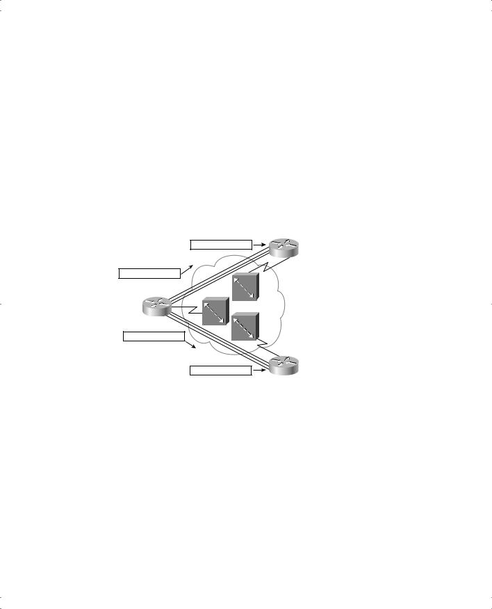
Global addressing is planned as shown in Figure 11-8, with the DLCIs placed in Frame Relay frames as shown in Figure 11-9. For example, Router A uses DLCI 41 when sending a frame to Router B, because Router B’s global DLCI is 41. Likewise, Router A uses DLCI 42 when sending frames over the VC to Router C. The nice thing is that global addressing is much more logical to most people, because it works like a LAN, with a single MAC address for each device. On a LAN, if the MAC addresses are MAC-A, MAC-B, and MAC-C for the three routers, Router A uses destination address MAC-B when sending frames to Router B and MAC-C as the destination to reach Router C. Likewise, with global DLCIs 40, 41, and 42 used for Routers A, B, and C, respectively, the same concept applies. Because DLCIs address VCs, the logic is something like this when Router A sends a frame to Router B: “Hey, local switch! When you get this frame, send it over the VC that we agreed to number with DLCI 41.” Figure 11-9 outlines this example.
Figure 11-9 Frame Relay Global Addressing from the Sender’s Perspective
|
B |
Frame with DLCI 40 |
Global |
|
DLCI 41 |
Frame with DLCI 41
A
Global
DLCI 40
Frame with DLCI 42
|
C |
|
Global |
Frame with DLCI 40 |
DLCI 42 |
Router A sends frames with DLCI 41, and they reach the local switch. The local switch sees the DLCI field and forwards the frame through the Frame Relay network until it reaches the switch connected to Router B. Then Router B’s local switch forwards the frame out the access link to Router B. The same process happens between Router A and Router C when Router
A uses DLCI 42. The beauty of global addressing is that you think of each router as having an address, like LAN addressing. If you want to send a frame to someone, you put his or her DLCI in the header, and the network delivers the frame to the correct DTE.
The final key to global addressing is that the Frame Relay switches actually change the DLCI value before delivering the frame. Did you notice that Figure 11-9 shows a different DLCI value as the frames are received by Routers B and C? For example, Router A sends a frame to Router B, and Router A puts DLCI 41 in the frame. The last switch changes the field to DLCI 40 before forwarding it to Router B. The result is that when Routers B and C receive their frames, the DLCI value is actually the sender’s DLCI. Why? Well, when Router B
Frame Relay Protocols 387
receives the frame, because the DLCI is 40, it knows that the frame came in on the PVC between itself and Router A. In general, the following are true:
■The sender treats the DLCI field as a destination address, using the destination’s global DLCI in the header.
■The receiver thinks of the DLCI field as the source address, because it contains the global DLCI of the frame’s sender.
Figure 11-9 describes what happens in a typical Frame Relay network. Service providers supply a planning spreadsheet and diagrams with global DLCIs listed. Table 11-5 gives you an organized view of what DLCIs are used in Figure 11-9.
Table 11-5 DLCI Swapping in the Frame Relay Cloud of Figure 11-9
Frame Sent by Router |
With DLCI Field |
Is Delivered to Router |
With DLCI Field |
|
|
|
|
A |
41 |
B |
40 |
|
|
|
|
A |
42 |
C |
40 |
|
|
|
|
B |
40 |
A |
41 |
|
|
|
|
C |
40 |
A |
42 |
|
|
|
|
Global addressing makes DLCI addressing more intuitive to most people. It also makes router configuration more straightforward and lets you add new sites more conveniently. For instance, examine Figure 11-10, which adds Routers D and E to Figure 11-9’s network. The service provider simply states that global DLCIs 43 and 44 are used for these two routers. If these two routers also have only one PVC to Router A, all the DLCI planning is complete. You know that Router D and Router E use DLCI 40 to reach Router A and that Router A uses DLCI 43 to reach Router D and DLCI 44 to reach Router E.
Figure 11-10 Adding Frame Relay Sites: Global Addressing
B
DLCI 41
D
DLCI 43
A
DLCI 40 |
E |
|
DLCI 44
C
DLCI 42