


580 Appendix E: Configuring Cisco 1900 Switches
Example E-1 show run Output Refers to Port e0/1 as Interface Ethernet 0/1 (Continued)
Designated port is Ethernet 0/1, path cost 0
Timers: message age 20, forward delay 15, hold 1
! Portions omitted for brevity...
wg_sw_a#show vlan-membership
Port VLAN Membership Type Port VLAN Membership Type
------------------------------------------------------------------
1 |
5 |
Static |
13 |
1 |
Static |
2 |
1 |
Static |
14 |
1 |
Static |
3 |
1 |
Static |
15 |
1 |
Static |
Basic IP and Port Duplex Configuration
Two features commonly configured during switch installation are TCP/IP support and the setting of duplex on key switch ports. Switches support IP, but in a different way than a router. The switch acts more like a normal IP host, with a single address/mask for the switch and a default router. Each port/interface does not need an IP address because the switch is not performing Layer 3 routing. In fact, if there were no need to manage the switch, IP would not be needed on the switch at all.
The second feature typically configured at installation time is to preconfigure some ports to always use halfor full-duplex operation rather than allow negotiation. At times, autonegotiation can produce unpredictable results. For example, if a device attached to the switch does not support autonegotiation, the Catalyst switch sets the corresponding switch port to half-duplex mode by default. If the attached device is configured for full-duplex operation, a duplex mismatch occurs. To avoid this situation, manually set the duplex parameters of the switch to match the attached device.
Similar to the router IOS, the Catalyst 1900 switch has various configuration modes. Example E-2 shows the initial configuration of IP and duplex, with the actual prompts showing the familiar exec and configuration modes.
Example E-2 Configuration Modes for Configuring IP and Duplex
wg_sw_a#configure terminal
wg_sw_a(config)#ip address 10.5.5.11 255.255.255.0 wg_sw_a(config)#ip default-gateway 10.5.5.3 wg_sw_a(config)# interface e0/1 wg_sw_a(config-if)#duplex half wg_sw_a(config-if)#end
wg_sw_a


582 Appendix E: Configuring Cisco 1900 Switches
Example E-3 show ip and show interfaces Output (Continued)
Frames filtered |
9 |
Single collisions |
0 |
Runt frames |
0 |
Multiple collisions |
0 |
No buffer discards |
0 |
Excessive collisions |
0 |
|
|
Queue full discards |
0 |
Errors: |
|
Errors: |
|
|
|
|
|
FCS errors |
0 |
Late collisions |
0 |
Alignment errors |
0 |
Excessive deferrals |
0 |
Giant frames |
0 |
Jabber errors |
0 |
Address violations |
0 |
Other transmit errors |
0 |
|
|
|
|
No IP address is in the show interface output because the IP address is associated with the entire switch, not just a single interface. The spanning-tree state of the interface is shown, as is the duplex setting. If duplex was mismatched with the device on the other end, the late collisions counter most likely would increment rapidly.
Viewing and Configuring Entries in the MAC Address Table
The switching/bridging table concept discussed earlier in this chapter is called the MAC address table on the 1900 family of switches. The MAC address table contains dynamic entries, which are learned when the switch receives frames and examines the source MAC address. Two other variations of entries in the MAC address table are important to switch configuration and are outlined along with dynamic entries in the following list:
■Dynamic addresses—MAC addresses are added to the MAC address table through normal bridge/switch processing. In other words, when a frame is received, the source MAC of the frame is associated with the incoming port/interface. These entries in the table time out with disuse (default 300 seconds on a 1900 series switch) and are cleared whenever the entire table is cleared.
■Permanent MAC addresses—Through configuration, a MAC address is associated with a port, just as it would have been associated as a dynamic address. However, permanent entries in the table never time out.
■Restricted-static entries—Through configuration, a MAC address is configured to be associated only with a particular port, with an additional restriction: Frames destined to that MAC address must have entered through a particular set of incoming ports.
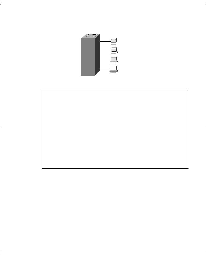
Figure E-1 provides a simple example to show the use of permanent and restricted-static addresses. A popular server (Server 1) is on port E0/3, and there is never a case when its MAC address should not be in the table. The payroll server is also on this switch, and only the company comptroller is allowed access. The configuration and resulting MAC address table are shown in Example E-4, which follows the figure.
Basic 1900 Switch Configuration 583
Figure E-1 MAC Address Table Manipulation—Sample Network
E0/1  Company
 Comptroller
E0/2 |
|
|
|
User1 |
||
|
|
|
||||
|
|
|
|
|
|
|
|
|
|
|
|
|
|
|
|
|
|
|
|
|
E0/3 |
|
|
|
Server 1 |
||
|
|
|
||||
|
|
|
|
|
|
0200.2222.2222 |
|
|
|
|
|
|
|
E0/4  Payroll Server
0200.1111.1111
Example E-4 The MAC Address Table, with Dynamic, Permanent, and Restricted Static Entries
wg_sw_a(config)#mac-address-table permanent 0200.2222.2222 ethernet 0/3 wg_sw_a(config)#mac-address-table restricted static 0200.1111.1111 e0/4 e0/1
wg_sw_a(config)#End |
|
|
|
wg_sw_a# |
|
|
|
wg_sw_a#show mac-address-table |
|
|
|
Number of permanent addresses : 1 |
|
|
|
Number of restricted static addresses : 1 |
|
||
Number of dynamic addresses : 5 |
|
|
|
Address |
Dest Interface |
Type |
Source Interface List |
----------------------------------------------------------------------
0200.4444.4444 |
Ethernet 0/1 |
Dynamic |
All |
00E0.1E5D.AE2F |
Ethernet 0/2 |
Dynamic |
All |
|
|
|
|
0200.2222.2222 |
Ethernet 0/3 |
Permanent |
All |
0200.1111.1111 |
Ethernet 0/4 |
Static |
Et0/1 |
00D0.588F.B604 |
FastEthernet 0/26 |
Dynamic |
All |
00E0.1E5D.AE2B |
FastEthernet 0/26 |
Dynamic |
All |
00D0.5892.38C4 |
FastEthernet 0/27 |
Dynamic |
All |
In the example, Server 1 is always in the address table as the permanent entry. The payroll server is always in the table off port 0/4, and only devices on port 0/1 are allowed to send frames to it.
Another feature affecting the MAC address table is called port security. Port security is a feature that, when enabled, limits the number of MAC addresses associated with a port in the MAC address table. In other words, there is a preset limit to the number of sources that can forward frames into that switch port.

584 Appendix E: Configuring Cisco 1900 Switches
An example is particularly useful for understanding this concept; the configuration is straightforward. Consider Figure E-2, which shows a similar configuration to Figure E- 1, except that the finance department has increased to three employees. These three employees are on the same shared hub, which then is cabled to switch port 0/1.
Figure E-2 Figure E-2 Sample Network with Port Security
|
|
|
|
|
|
|
|
|
|
|
|
|
Company Comptroller |
|
|
|
E0/1 |
|
|
|
|
|
|
|
|
|
0200.4444.4444 |
|
|
|
|
|
|
|
|
|
|
|
|
||
|
|
|
|
|
|
|
|
|
|
|
|
Payroll Clerk |
|
|
|
|
|
|
|
|
|
|
|
|
|
||
|
|
|
|
|
|
|
|
|
|
|
|
|
0200.5555.5555 |
|
|
|
|
|
|
|
|
|
|
|
|
|
|
|
|
|
|
|
|
|
|
|
|
|
|
|
Receivables Clerk |
|
|
|
E0/2 |
|
|
User1 |
|
|
|
|
|
||
|
|
|
|
|
|
|
|
|
|||||
|
|
|
|
|
|
|
|
|
|||||
|
|
|
|
|
|
|
|
|
0200.6666.6666 |
||||
|
|
|
|
|
|
|
|
|
|||||
|
|
|
|
|
|
|
|
|
|
|
|
|
|
|
|
|
|
|
|
|
|
|
|
|
|
|
|
|
|
|
E0/3 |
|
Server 1 |
|
|||||||
|
|
|
|
|
|||||||||
|
|
|
|
|
|
0200.2222.2222 |
|
||||||
|
|
|
|
|
|
|
|
|
|
|
|
|
|
|
|
|
E0/4 |
|
Payroll Server |
|
|||||||
|
|
|
|
|
|||||||||
|
|
|
|
|
|
0200.1111.1111 |
|
||||||
|
|
|
|
|
|
|
|||||||
|
|
|
|
|
|
|
|
|
|
|
|
|
|
Port security can be used to restrict port 0/1 so that only three MAC addresses can source frames that enter port 0/1; this is because only the finance department is expected to use the shared hub. Any permanent or restricted-static MAC addresses count against this total of three. Example E-5 shows a sample configuration, with show commands.
Example E-5 Port Security Example
wg_sw_a(config)#mac-address-table permanent 0200.2222.2222 ethernet 0/3 wg_sw_a(config)#mac-address-table permanent 0200.4444.4444 ethernet 0/1 wg_sw_a(config)#mac-address-table restricted static 0200.1111.1111 e0/4 e0/1 wg_sw_a(config)#interface ethernet 0/1
wg_sw_a(config-if)#port secure max-mac-count 3 wg_sw_a(config-if)#End
wg_sw_a#
wg_sw_a#show mac-address-table
Number of permanent addresses : 2
Number of restricted static addresses : 1
Number of dynamic addresses : 6
Address Dest Interface Type Source Interface List
----------------------------------------------------------------------
0200.4444.4444 |
Ethernet 0/1 |
Permanent |
All |
0200.5555.5555 |
Ethernet 0/1 |
Dynamic |
All |
0200.6666.6666 |
Ethernet 0/1 |
Dynamic |
All |
00E0.1E5D.AE2F |
Ethernet 0/2 |
Dynamic |
All |
0200.2222.2222 |
Ethernet 0/3 |
Permanent |
All |
|
|
|
|
0200.1111.1111 |
Ethernet 0/4 |
Static |
Et0/1 |
00D0.588F.B604 |
FastEthernet 0/26 |
Dynamic |
All |


586 Appendix E: Configuring Cisco 1900 Switches
Managing Configuration and System Files
Commands that are used to manage and control the configuration and system software files are slightly different on the 1900 switch family than on IOS-based routers. One of the reasons for the difference is that the switch does not actually run IOS—it has many features similar to IOS, including the IOS CLI, but there are and probably always will be some differences. For example, in Example E-6, the familiar show version command is used to display uptime and software levels, but it does not show the IOS level because IOS is not running.
Example E-6 show version Output Displays Switch Hardware and Cisco IOS Software Information
wg_sw_a#show version
Cisco Catalyst 1900/2820 Enterprise Edition Software
Version V9.00.00(12) written from 171.071.114.222
Copyright Cisco Systems, Inc. 1993-1999
DS2820-1 uptime is 2day(s) 19hour(s) 34minute(s) 41second(s)
cisco Catalyst 2820 (486sxl) processor with 2048K/1024K bytes of memory Hardware board revision is 1
Upgrade Status: No upgrade currently in progress.
Config File Status: No configuration upload/download is in progress 25 Fixed Ethernet/IEEE 802.3 interface(s)
SLOT A:
FDDI (Fiber DAS Model), Version 00
v1.14 written from 172.031.004.151: valid SLOT B:
100Base-TX(1 Port UTP Model), Version 0 Base Ethernet Address: 00-E0-1E-87-21-40
Another difference is that when the configuration is changed, the running config is modified but the startup config file in NVRAM is automatically updated. In other words, there is no need for a copy running-config startup-config command on the 1900 family of switches, as there would be on a router. Configuration files can be copied to an external TFTP server, but instead of using the keyword startup-config (used by routers), NVRAM is used.
The syntax of the command used to copy the NVRAM configuration file to host 10.1.1.1 into file mybackup.cfg is copy nvram tftp://10.1.1.1/mybackup.cfg. Unlike the router IOS, the switch IOS CLI will not prompt for the server name or IP address or the name of the file. Instead, the address or server host name and the filename are entered at the command line. The fact that the command does not prompt you is certainly different than with the router IOS. However, the same general syntax is available on the router IOS as of Cisco IOS Software release 12.0. For example, a similar, valid router IOS command would be copy startup-config tftp://10.1.1.1/myrouter.cfg.

VLAN and Trunking Configuration 587
Table E-3 summarizes some of the key differences between the router IOS CLI and the 1900 IOS CLI.
Table E-3 IOS CLI Differences: Router Versus 1900 Switch
|
Router Command, |
Switch Command, |
Function |
Features |
Features |
|
|
|
Finding software version |
show version command; |
show version command; |
|
shows IOS version. |
shows switch software |
|
|
version. |
|
|
|
Copying configuration files to |
copy startup-config tftp |
copy nvram tftp://server/file |
TFTP server |
command; router IOS |
command; switch IOS CLI |
|
prompts for TFTP |
does not prompt for TFTP |
|
parameters. |
parameters. “Server” can be |
|
|
IP address or host name. |
|
|
|
Updating the config file used |
copy running-config |
Changes made to running |
at reload time |
startupconfig command. |
configuration using config |
|
|
mode automatically are |
|
|
reflected in NVRAM config |
|
|
file. |
|
|
|
Erasing the config file used at |
write erase or erase |
delete nvram command. |
reload time |
startupconfig command. |
|
|
|
|
VLAN and Trunking Configuration
This section covers VLAN configuration, as well as VTP configuration, on a 1900 series switch.
Basic VLAN Configuration
You should remember several items before you begin VLAN configuration:
■The maximum number of VLANs is switch-dependent. The Catalyst 1900 supports 64 VLANs with a separate spanning tree per VLAN.
■VLAN 1 is one of the factory-default VLANs.
■CDP and VTP advertisements are sent on VLAN 1.
■Catalyst 1900 IP address is in the VLAN 1 broadcast domain.
■The switch must be in VTP server mode or transparent mode to create, add, or delete VLANs.

588 Appendix E: Configuring Cisco 1900 Switches
Table E-4 represents the commands covered in this section and gives a brief description of each command’s function.
Table E-4 VLAN Command List
Command |
Description |
|
|
delete vtp |
Resets all VTP parameters to defaults and |
|
resets the configuration revision number to 1 |
|
|
vtp [server | transparent | client] [domain |
Defines VTP parameters |
domain-name] [trap {enable | disable}] |
|
[password password] [pruning {enable | |
|
disable}] |
|
|
|
vtp trunk pruning-disable vlan-list |
Disables pruning for specified VLANs on a |
|
particular trunk interface (interface |
|
subcommand) |
|
|
show vtp |
Displays VTP status |
|
|
trunk [on | off | desirable | auto | nonegotiate] |
Configures a trunk interface |
|
|
show trunk {A | B | port-channel} [allowed- |
Displays trunk status |
vlans | prune-eligible | joined-vlans | joining- |
|
vlans] |
|
|
|
vlan vlan [name vlan-name] [state |
Defines a VLAN and its name |
{operational | suspended}] |
|
|
|
show vlan [vlan] |
Displays VLAN information |
|
|
vlan-membership {static {vlan} | dynamic} |
Assigns a port to a VLAN |
|
|
show vlan-membership |
Displays VLAN membership |
|
|
show spantree [bridge-group | vlan] |
Displays spanning tree information for a |
|
VLAN |
|
|
VLAN Configuration for a Single Switch
If only one switch is in use, there is no real benefit to using VTP. However, VTP is on in server mode by default. Because VTP does not help when using a single switch, the first example shows VTP functions being turned off by enabling VTP transparent mode. The steps taken in this example are listed here:
1.Enabling VTP transparent mode
2.Creating the VLAN numbers and names
3.Configuring each port’s assigned VLAN

590 Appendix E: Configuring Cisco 1900 Switches
Example E-7 Single-Switch VLAN Configuration Matching Figure E-3 (Continued)
switch1(config-if)# interface e 0/9 switch1(config-if)# vlan-membership static 3 switch1(config-if)# interface e 0/10 switch1(config-if)# vlan-membership static 3 switch1(config-if)# interface e 0/11 switch1(config-if)# vlan-membership static 3 switch1(config-if)# interface e 0/12 switch1(config-if)# vlan-membership static 3
Notice that some configuration seems to be missing. VLAN 1, with name VLAN 1, is not configured because it is configured automatically. In fact, the name cannot be changed. Also, any ports without a specific static VLAN configuration are considered to be in VLAN 1. Also, the IP address of the switch is considered to be in VLAN 1’s broadcast domain. Ports 5 through 8 are statically configured for VLAN 2; similarly, VLAN 3 comprises ports 9 through 12. In addition, VTP is set to transparent mode, with a meaningless domain name of dummy.
After the VLANs are configured, the parameters for that VLAN should be confirmed to ensure validity. To verify the parameters of a VLAN, use the show vlan vlan# privileged exec command to display information about a particular VLAN. Use show vlan to show all configured VLANs. Example E-8 demonstrates the show command output, which shows the switch ports assigned to the VLAN.
Example E-8 show vlan Output
Switch1#show vlan 3 |
|
|
VLAN Name |
Status |
Ports |
------------------------------------------------- |
||
3 VLAN3 |
Enabled |
9-12 |
------------------------------------------------- |
||
VLAN Type |
SAID MTU |
Parent RingNo BridgeNo Stp Trans1 Trans2 |
--------------------------------------------------------------------------------
3 Ethernet 100003 1500 0 1 1 Unkn 0 0
--------------------------------------------------------------------------------
Other VLAN parameters shown in Example 5-3 include the type (default is Ethernet), SAID (used for FDDI trunk), MTU (default is 1500 for Ethernet VLAN), Spanning-Tree Protocol (the 1900 supports only the 802.1D Spanning-Tree Protocol standard), and other parameters used for Token Ring or FDDI VLANs.

VLAN and Trunking Configuration 591
Sample Configuration for Multiple Switches
To allow VLANs to span multiple switches, you must configure trunks to interconnect the switches. Trunks are simply LAN segments that connect switches and use one of two methods of tagging the frames with the VLAN number. Cisco calls the use of a trunking protocol such as ISL or 802.1Q trunking, so the command to enable these protocols is trunk.
Use the trunk interface configuration command to set a Fast Ethernet port to trunk mode. On the Catalyst 1900, the two Fast Ethernet ports are interfaces fa0/26 and fa0/27. Enabling and defining the type of trunking protocol can be done statically or dynamically for ISL. The syntax for the trunk Fast Ethernet interface configuration subcommand is as follows:
switch(config-if)# trunk [on | off | desirable | auto | nonnegotiate]
The options for the trunk command function are as follows:
■on—Configures the port into permanent ISL trunk mode and negotiates with the connected device to convert the link to trunk mode.
■off—Disables port trunk mode and negotiates with the connected device to convert the link to nontrunk.
■desirable—Triggers the port to negotiate the link from nontrunking to trunk mode. The port negotiates to a trunk port if the connected device is either in the on, desirable, or auto states. Otherwise, the port becomes a nontrunk port.
■auto—Enables a port to become a trunk only if the connected device has the state set to on or desirable.
■nonegotiate—Configures a port to permanent ISL trunk mode, and no negotiation takes place with the partner.
As seen in the list, many options exist. Choices for these options are mostly personal preference. Because trunks seldom change, my preference is to configure either on or off.
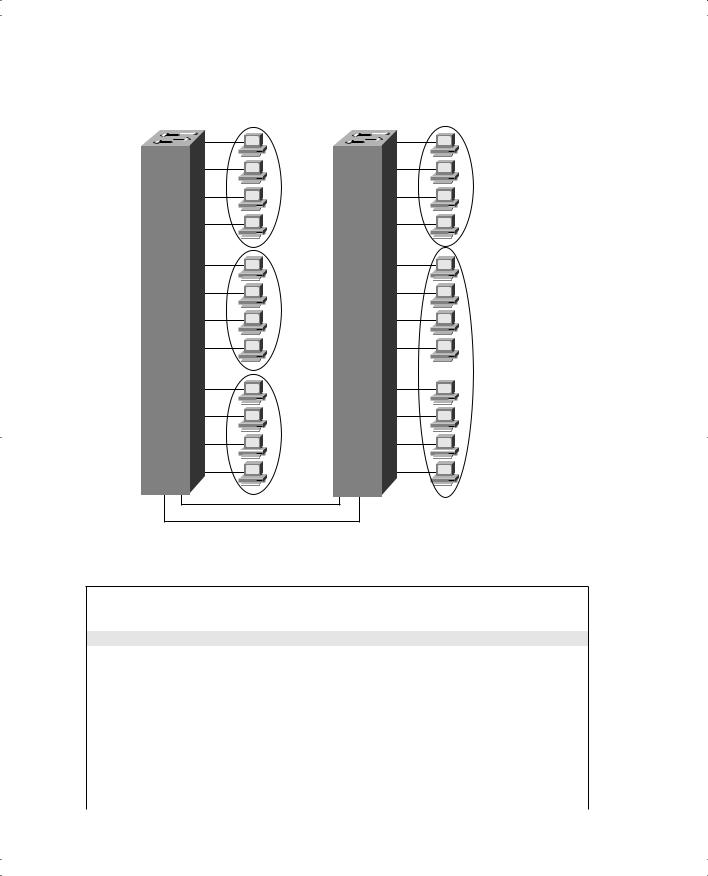
Figure E-4 and Examples E-9 and E-10 provide an expanded sample network, along with the additional configuration required for trunking and VTP server configuration.
592 Appendix E: Configuring Cisco 1900 Switches
Figure E-4 Sample Network with Two Switches and Three VLANs
Switch 1 |
Switch 2 |
|
0/1 |
VLAN 1 |
VLAN 1 |
0/5
VLAN 2
VLAN 3
0/9
VLAN 3
0/26
0/27
Example E-9 Switch 1 Complete Configuration as VTP Server
switch1# configure terminal
switch1(config)#ip address 10.5.5.11 255.255.255.0 switch1(config)#ip default-gateway 10.5.5.3
switch1(config)# vtp server domain Hartsfield pruning enable
switch1(config)# vlan 2 name VLAN2 switch1(config)# vlan 3 name VLAN3 switch1(config)# interface e 0/5 switch1(config-if)# vlan-membership static 2 switch1(config-if)# interface e 0/6 switch1(config-if)# vlan-membership static 2 switch1(config-if)# interface e 0/7 switch1(config-if)# vlan-membership static 2 switch1(config-if)# interface e 0/8 switch1(config-if)# vlan-membership static 2 switch1(config-if)# interface e 0/9


594 Appendix E: Configuring Cisco 1900 Switches
Several items are particularly important in these configurations. The vtp global command in Example E-9 shows Switch 1 as the server, with domain Hartsfield. No password is used in this case. Switch 2 is not configured with the domain name but will learn it with the first advertisement. Missing from Example E-10 is the definition of the VLANs, which not only is unnecessary but also is not allowed when in VTP client mode. And because pruning was enabled in the vtp command on Switch 1, VTP prunes VLAN 2 from Switch 2 because Switch 2 has no ports in VLAN 2. VLAN 2 broadcasts received by Switch 1 are not forwarded to Switch 2.
Notice that not only was trunking enabled on both Fast Ethernet ports, but each of the three VLANs was statically configured on those ports. By also configuring the VLANs, the switch treats the trunk ports as part of those VLANs.
To verify a recent configuration change, or to just view the VTP configuration information, use the show vtp privileged exec command, as demonstrated in Example E-11. Also displayed is the IP address of the device that last modified the configuration and a time stamp of the time the modification was made. VTP has two versions: VTP Version 1 supports only Ethernet; VTP Version 2 supports Ethernet and Token Ring.
Example E-11 show vtp Command Output
switch1# show vtp
VTP version: 1
Configuration revision: 4
Maximum VLANs supported locally: 1005
Number of existing VLANs: 3
VTP domain name:Hartsfield
VTP password:
VTP operating mode: Server
VTP pruning mode: Enabled
VTP traps generation: Enabled
Configuration last modified by: 10.5.5.3 at 00-00-0000 00:00:00
To verify a trunk configuration, use the show trunk privileged exec command to display the trunk parameters, as demonstrated in Example E-12. The syntax is as follows:
switch1# show trunk [a | b]
The parameters a and b represent the Fast Ethernet ports:
■Port a represents Fast Ethernet 0/26.
■Port b represents Fast Ethernet 0/27.


596 Appendix E: Configuring Cisco 1900 Switches
Example E-13 show spantree Output (Continued)
Designated bridge has priority 32768, address 0050.F037.DA00
Designated port is Ethernet 0/1, path cost 10
Timers: message age 20, forward delay 15, hold 1
Example E-13 displays various spanning tree information for VLAN 1, including the following:
■Port e0/1 is in the forwarding state for VLAN 1.
■The root bridge for VLAN 1 has a bridge priority of 0, with a MAC address of
00D0.588F.B600.
■The switch is running the IEEE 802.1d Spanning Tree Protocol.


G L O S S A R Y
802.1Q The IEEE standardized protocol for VLAN trunking.
access link The leased line between the Frame Relay DTE and DCE.
ACL Access Control List. A list configured on a router to control packet flow through the router, such as to prevent packets with a certain IP address from leaving a particular interface on the router.
AR access rate. The speed at which the access link is clocked. This choice affects the connection’s price.
ARP Address Resolution Protocol. An Internet protocol used to map an IP address to a MAC address. Defined in RFC 826.
asynchronous Describes digital signals that are transmitted without precise clocking. Such signals generally have different frequencies and phase relationships. Asynchronous transmissions usually encapsulate individual characters in control bits (called start and stop bits) that designate the beginning and end of each character.
autosummarization When advertised on an interface whose IP address is not in network X, routes related to subnets in network X are summarized and advertised as one route. That route is for the entire Class A, B, or C network X. Autosummarization is a feature of some IP routing protocols.
balanced hybrid Refers to a third general type of routing protocol algorithm—the other two being distance vector and link-state. EIGRP is the only routing protocol that Cisco classifies as using a balanced hybrid algorithm.
Bc committed burst. Over time, Bc defines the number of bits that can be sent consecutively at the access rate without exceeding the traffic contract.
BECN backward explicit congestion notification. The bit in the Frame Relay header that signals to anything receiving the frame (switches and DTEs) that congestion is occurring in the opposite (backward) direction from the frame. Switches and DTEs can react by slowing the rate at which data is sent in that direction.

600 blocking state
blocking state A Spanning Tree Protocol port state in which the bridge or switch does not process any frames (input or output) on the interface, with the exception of STP messages.
Boolean AND A math operation performed on a pair of one-digit binary numbers. The result is another one-digit binary number. 1 AND 1 yields 1; all other combinations yield 0.
BRI Basic Rate Interface. An ISDN interface composed of two bearer (B) channels and one data (D) channel for circuit-switched communication of voice, video, and data.
bridge ID An 8-byte value, defined for use by Spanning Tree Protocol, that represents a bridge or switch. The first 2 bytes consist of a priority value, and the last 6 bytes typically consist of a MAC address on the bridge or switch.
broadcast address An IP address in each subnet is considered the broadcast address for that subnet. It is the highest numerical value in the range of numbers for the subnet. The broadcast address cannot be assigned as an IP address to a computer. Packets sent to this address are delivered to all hosts in the subnet.
broadcast domain A set of all devices that receive broadcast frames originating from any device in the set. Devices in the same VLAN are in the same broadcast domain.
broadcast subnet When subnetting a Class A, B, or C network, two subnet numbers are “discouraged” from use; one of these two subnets is the broadcast subnet. It is the subnet number for which the subnet bits all have a value of binary 1.
CHAP Challenge Handshake Authentication Protocol. A security feature supported on lines using PPP encapsulation that prevents unauthorized access. CHAP does not itself prevent unauthorized access; it merely identifies the remote end. The router or access server then determines whether that user is allowed access.
CIDR classless interdomain routing. A technique supported by BGP-4 and based on route aggregation. CIDR allows routers to group routes to reduce the quantity of routing information carried by the core routers. With CIDR, several IP networks appear to networks outside the group as a single, larger entity.
CIR committed information rate. The rate at which the DTE can send data for an individual VC, for which the provider commits to deliver that amount of data. The provider sends any data in excess of this rate for this VC if its network has capacity at the time. This choice typically affects the price of each VC.

deny 601
circuit switching The switching system in which a dedicated physical circuit path must exist between the sender and the receiver for the duration of the “call.” Used heavily in the telephone company network.
classful routing Routing logic that first matches the Class A, B, or C network in the routing table. If the network number is matched, and then the correct subnet number matching a packet’s destination IP address is not found, any existing default route is not used.
classful routing protocol Does not transmit the mask information along with the subnet number. Therefore, it must consider Class A, B, and C network boundaries and perform autosummarization at Class A, B, and C network boundaries. Does not support VLSM.
classless routing Routing logic that does not bother matching the Class A, B, or C network in the routing table. If the correct subnet number matching a packet’s destination IP address is not found, any existing default route is used.
classless routing protocol Transmits the mask information along with the subnet number, which means that it does not have to consider Class A, B, and C network boundaries. Although autosummarization at Class A, B, and C network boundaries may be supported, it is not required. Does not support VLSM.
CSU/DSU channel service unit/data service unit. The CSU component is a digital interface device that connects end-user equipment to the local digital telephone loop. The DSU component is a device used in digital transmission that adapts the physical interface on a data terminal equipment (DTE) device to a transmission facility, such as T1 or E1. The DSU also is responsible for functions such as signal timing.
DCE data communications equipment. From a physical layer perspective, the device providing the clocking on a WAN link, typically a CSU/DSU, is the DCE. From a packet switching perspective, the Service Provider’s switch, to which a router might connect, is considered the DCE.
DDR dial-on-demand routing. A technique whereby a router can automatically initiate and close a circuit-switched session as transmitting stations demand. The router spoofs keepalives so that end stations treat the session as active. DDR permits routing over ISDN or telephone lines.
DE discard eligible. The bit in the Frame Relay header that, if frames must be discarded, signals a switch to choose this frame to discard instead of another frame without the DE bit set.
deny An action taken with an ACL that implies that the packet is discarded.

602 designated port
designated port The port (interface) on a bridge or switch that advertises the best spanningtree BPDU (hello message) onto a LAN segment.
directed broadcast address The same as a broadcast address.
discarding state A Rapid Spanning Tree Protocol port state that is used instead of the blocking, listening, and disabled states in STP.
distance vector The logic behind the behavior of some interior routing protocols, such as RIP and IGRP. Distance vector routing algorithms call for each router to send its entire routing table in each update, but only to its neighbors. Distance vector routing algorithms can be prone to routing loops but are computationally simpler than link-state routing algorithms. Also called Bellman-Ford routing algorithm.
DLCI data-link connection identifier. A Frame Relay address used in Frame Relay headers to identify the VC.
DTE data terminal equipment. From a Layer 1 perspective, the DTE synchronizes its clock based on the clock sent by the DCE. From a Packet Switching perspective, the DTE is the device outside the Service Provider's network, typically a router.
DUAL Diffusing Update Algorithm. A convergence algorithm used in EIGRP that provides loop-free operation at every instant throughout a route computation. Allows routers involved in a topology change to synchronize at the same time, while not involving routers that are unaffected by the change.
EIGRP Enhanced Interior Gateway Routing Protocol. An advanced version of IGRP developed by Cisco. Provides superior convergence properties and operating efficiency and combines the advantages of link-state protocols with those of distance vector protocols.
encoding The conventions for how a device varies the electrical or optical signals sent over a cable to imply a particular binary code. For instance, a modem might encode a binary 1 or
0 by using one frequency to mean 1 and another to mean 0.
EtherChannel Developed and copyrighted by Cisco Systems. A logical aggregation of multiple Ethernet interfaces used to form a single higher-bandwidth routing or bridging endpoint.
feasible successor To converge quickly, EIGRP keeps track of possible alternative next-hop routers for each route. A feasible successor is a neighboring router that can be used as a replacement next-hop router for a particular route when it fails.

holddown 603
FECN forward explicit congestion notification. The bit in the Frame Relay header that signals to anything receiving the frame (switches and DTEs) that congestion is occurring in the same direction as the frame.
filter Generally, a process or a device that screens network traffic for certain characteristics, such as source address, destination address, or protocol, and determines whether to forward or discard that traffic based on the established criteria.
forward To send a frame toward its ultimate destination by way of an internetworking device.
Forward Delay timer A timer that sets the amount of time an interface spends in the STP listening and learning states. In other words, an interface stays in each of these two states for the Forward Delay amount of time.
forwarding state A Spanning Tree Protocol port state in which the bridge or switch processes frames (input or output) on the interface, with the exception of STP messages.
framing The conventions for how the bits sent according to OSI Layer 1 are interpreted by Layer 2. For instance, after an electrical signal has been received and converted to binary, framing identifies the information fields inside the data.
FTP File Transfer Protocol. An application protocol, part of the TCP/IP protocol stack, used to transfer files between network nodes. FTP is defined in RFC 959.
function group An ISDN term that generically refers to a set of functions that a piece of hardware or software must perform. Because the ITU wanted several options for the customer, it defined multiple different function groups. See also reference point.
HDLC High-Level Data Link Control. A bit-oriented synchronous data link layer protocol developed by the International Organization for Standardization (ISO). Derived from synchronous data link control (SDLC), HDLC specifies a data encapsulation method on synchronous serial links using frame characters and checksums.
hello timer An STP timer that dictates how often the root bridge or switch sends STP hello messages. It also dictates how often nonroot bridges and switches should expect to hear these hello messages. This term may also refer to the Hello timer used by OSPF, which defines how often a router sends OSPF Hello messages.
Hello A protocol used by OSPF systems to establish and maintain neighbor relationships. Can also refer to the STP Hello BPDU message generates by the root bridge in a Spanning Tree.
holddown A state into which a route is placed so that routers neither advertise the route nor accept advertisements about it for a specific length of time (the hold-down period). Holddown is used to flush bad information about a route from all routers in the network. A route typically is placed in holddown when a link in that route fails.

604 IGRP
IGRP Interior Gateway Routing Protocol. An Interior Gateway Protocol (IGP) developed by Cisco to address the issues associated with routing in large, heterogeneous networks.
ISDN Integrated Services Digital Network. A communication protocol offered by telephone companies that permits telephone networks to carry data, voice, and other source traffic.
ISL Inter-Switch Link. A Cisco-proprietary protocol that maintains VLAN information as traffic flows between switches and routers.
LAPF Link Access Procedure Frame Bearer Services. Defines the basic Frame Relay header and trailer. The header includes DLCI, FECN, BECN, and DE bits.
learn Transparent bridges and switches learn MAC addresses by examining the source MAC addresses of frames they receive. They add each new MAC address, along with the port number of the port on which it learned of the MAC address, to an address table.
leased line A transmission line reserved by a communications carrier for a customer’s private use. A leased line is a type of dedicated line.
link-state A type of routing protocol which sends full topology information about the network to all routers, so they all have a consistent view of the network topology and status. Link-state algorithms create a consistent view of the network and therefore are not prone to routing loops. However, they achieve this at the cost of relatively greater computational difficulty and more-widespread traffic (compared with distance vector routing algorithms).
LMI Local Management Interface. The protocol used between a Frame Relay DCE and DTE to manage the connection. Signaling messages for SVCs, PVC status messages, and keepalives are all LMI messages.
LSA Link-State Advertisement. A packet used by link-state protocols that contains information about neighbors and path costs. LSAs are used by the receiving routers to maintain their routing tables.
mask See subnet mask.
MaxAge timer An STP timer that defines how long a bridge or switch should wait after the last received hello message before believing that the network topology has changed, and it can no longer hear the hello messages sent by the root bridge or switch.

poison reverse 605
metric A unit of measure used by routing protocol algorithms to determine the best pathway for traffic to use to reach a particular destination.
MLP Multilink Point-to-Point Protocol. A method of splitting, recombining, and sequencing datagrams across multiple point-to-point WAN links.
MTU maximum transmission unit. The maximum packet size, in bytes, that a particular interface can handle.
NAT Network Address Translation. A mechanism for reducing the need for globally unique IP addresses. NAT allows an organization with addresses that are not globally unique to connect to the Internet by translating those addresses into globally routable address space.
NBMA nonbroadcast multiaccess. A network in which broadcasts are not supported, but more than two devices can be connected.
neighbor A router that has an interface to a common network.
OSPF Open Shortest Path First. A link-state, hierarchical Interior Gateway Protocol (IGP) routing algorithm proposed as a successor to Routing Information Protocol (RIP) in the Internet community. OSPF features include least-cost routing, multipath routing, and load balancing. OSPF was derived from an early version of the Intermediate System-to- Intermediate System (IS-IS) protocol.
packet switching Service in which each DTE device connects to a telco using a single physical line, with the possibility of being able to forward traffic to all other sites. The telco switch makes the forwarding decision based on an address in the packet header.
PAP Password Authentication Protocol. An authentication protocol that allows PPP peers to authenticate one another. Unlike Challenge Handshake Authentication Protocol (CHAP), PAP passes the password and the host name or username in the clear (unencrypted). PAP is supported only on PPP lines.
permit An action taken with an ACL that implies that the packet is allowed to proceed through the router and be forwarded.
poison reverse A routing update that explicitly indicates that a network or subnet is unreachable, rather than implying that a network is unreachable by not including it in updates. Poison reverse updates are sent to defeat large routing loops.

606 port
port A TCP/IP transport layer header field found in TCP and UDP headers. Ports are numbers, and each numbered port is associated with a specific process. For example, SMTP is associated with port 25.
PPP Point-to-Point Protocol. A data-link protocol that provides router-to-router and host- to-network connections over synchronous and asynchronous circuits. PPP was designed to work with several network layer protocols, such as IP, IPX, and AppleTalk Remote Access (ARA).
PRI Primary Rate Interface. An ISDN interface to primary rate access. Primary rate access consists of a single 64-kbps D channel plus 23 (T1) or 30 (E1) B channels for voice or data.
private addresses IP addresses in several Class A, B, and C networks that are set aside for use inside private organizations. These addresses, as defined in RFC 1918, are not routable through the Internet.
protocol type A field in the IP header that identifies the type of header that follows the IP header, typically a Layer 4 header, such as TCP or UDP. ACLs can examine the protocol type to match packets with a particular value in this header field.
PVC permanent virtual circuit. A predefined VC. A PVC can be equated to a leased line in concept.
Q.921 An ITU-T specification for the ISDN User-Network Interface (UNI) data link layer.
Q.931 An ITU-T specification for signaling to establish, maintain, and clear ISDN network connections.
reference point An ISDN term that refers to the various interfaces between ISDN devices that implement different ISDN function groups.
RIP Routing Information Protocol. An Interior Gateway Protocol (IGP) supplied with
UNIX Berkeley Standard Distribution (BSD) systems. RIP is the most common IGP in the Internet. It uses hop count as a routing metric.
root bridge A bridge that exchanges topology information with designated bridges in a spanning-tree implementation to notify all other bridges in the network when topology changes are required.

SVC 607
route summarization A consolidation of advertised addresses which causes a single summary route to be advertised.
RSTP Rapid Spanning Tree Protocol, defined in IEEE 802.1w, defines an improved version of STP that converges much more quickly and consistently than STP (802.1d).
SLSM Static-length subnet mask. The usage of the same subnet mask for all subnets of a single Class A, B, or C network.
Spanning Tree Protocol A bridge protocol that uses the Spanning Tree algorithm, allowing a learning bridge to dynamically work around loops in a network topology by creating a spanning tree. Bridges exchange bridge protocol data unit (BPDU) messages with other bridges to detect loops and then remove the loops by shutting down selected bridge interfaces. Refers to both the IEEE 802.1d Spanning Tree Protocol standard and the earlier
Digital Equipment Corporation Spanning Tree Protocol upon which it is based. The IEEE version supports bridge domains and allows the bridge to construct a loop-free topology across an extended LAN. The IEEE version generally is preferred over the Digital version.
split horizon A routing technique in which information about routes is prevented from exiting the router interface through which that information was received. Split-horizon updates are useful in preventing routing loops.
subinterface One of the virtual interfaces on a single physical interface.
subnet Subnets are subdivisions of a Class A, B, or C network, as configured by a network administrator. Subnets allow a single Class A, B, or C network to be used and still allow for a large number of groups of IP addresses, as is required for efficient IP routing.
subnet broadcast address The same as a broadcast address.
subnet mask A 32-bit address mask used to indicate the bits of an IP address that are being used for the subnet part of the address. Sometimes simply called a mask.
successor In EIGRP, a neighboring router that could possibly be an alternative next-hop router to reach a particular subnet. Successors might or might not be feasible successors.
SVC switched virtual circuit. A VC that is set up dynamically when needed. An SVC can be equated to a dial connection in concept.

608 switch
switch A network device that filters, forwards, and floods frames based on each frame’s destination address. The switch operates at the data link layer of the Open System Interconnection (OSI) reference model.
synchronous The imposition of time ordering on a bit stream. Practically, a device will try to use the same speed as another device on the other end of a serial link. However, by examining transitions between voltage states on the link, the device can notice slight variations in the speed on each end and can adjust its speed accordingly.
TFTP Trivial File Transfer Protocol. A simplified version of File Transfer Protocol (FTP) that allows files to be transferred from one computer to another over a network, usually without the use of client authentication (for example, username and password).
topology database The structured data that describes the network topology to a routing protocol. Link-state and balanced hybrid routing protocols use topology tables, from which they build the entries in the routing table.
trunking Also called VLAN trunking. A method (using either Cisco’s ISL protocol or the IEEE 802.1Q protocol) to support multiple VLANs that have members on more than one switch.
update timer The time interval that regulates how often a routing protocol sends its next periodic routing updates. Distance vector routing protocols send full routing updates every update interval.
variance IGRP and EIGRP compute their metrics, so the metrics for different routes to the same subnet seldom have the exact same value. The variance value is multiplied with the lower metric when multiple routes to the same subnet exist. If the product is larger than the metrics for other routes, the routes are considered of “equal” metric, allowing multiple routes to be added to the routing table.
VC virtual circuit. A logical concept that represents the path that frames travel between
DTEs. VCs are particularly useful when comparing Frame Relay to leased physical circuits.
VLAN Virtual LAN. A group of devices on one or more LANs that are configured (using management software) so that they can communicate as if they were attached to the same wire when in fact they are located on a number of different LAN segments. Because VLANs are based on logical instead of physical connections, they are extremely flexible.
VLSM Variable-length subnet mask(ing). The capability to specify a different subnet mask for the same Class A, B, or C network number on different subnets. VLSM can help optimize available address space.
zero subnet 609
VTP VLAN Trunking Protocol. Cisco switches use this proprietary protocol to exchange VLAN configuration information between switches. VTP defines a Layer 2 messaging protocol that allows the switches to exchange VLAN configuration information so that the VLAN configuration stays consistent throughout a network. VTP manages the additions, deletions, and name changes of VLANs across multiple switches. It also reduces broadcast overhead through the use of VTP pruning.
zero subnet When subnetting a Class A, B, or C network, two subnet numbers are “discouraged” from use; the zero subnet is one of these two subnets. It is the subnet number for which the subnet bits all have a value of binary 0.