
- •Warning and Disclaimer
- •Feedback Information
- •Trademark Acknowledgments
- •About the Author
- •About the Technical Reviewers
- •Dedication
- •Acknowledgments
- •Contents at a Glance
- •Contents
- •Icons Used in This Book
- •Command Syntax Conventions
- •Cisco’s Motivation: Certifying Partners
- •Format of the CCNA Exams
- •What’s on the CCNA Exams
- •ICND Exam Topics
- •Cross-Reference Between Exam Topics and Book Parts
- •CCNA Exam Topics
- •INTRO and ICND Course Outlines
- •Objectives and Methods
- •Book Features
- •How This Book Is Organized
- •Part I: LAN Switching
- •Part II: TCP/IP
- •Part III: Wide-Area Networks
- •Part IV: Network Security
- •Part V: Final Preparation
- •Part VI: Appendixes
- •How to Use These Books to Prepare for the CCNA Exam
- •For More Information
- •Part I: LAN Switching
- •“Do I Know This Already?” Quiz
- •Foundation Topics
- •Brief Review of LAN Switching
- •The Forward-Versus-Filter Decision
- •How Switches Learn MAC Addresses
- •Forwarding Unknown Unicasts and Broadcasts
- •LAN Switch Logic Summary
- •Basic Switch Operation
- •Foundation Summary
- •Spanning Tree Protocol
- •“Do I Know This Already?” Quiz
- •Foundation Topics
- •Spanning Tree Protocol
- •What IEEE 802.1d Spanning Tree Does
- •How Spanning Tree Works
- •Electing the Root and Discovering Root Ports and Designated Ports
- •Reacting to Changes in the Network
- •Spanning Tree Protocol Summary
- •Optional STP Features
- •EtherChannel
- •PortFast
- •Rapid Spanning Tree (IEEE 802.1w)
- •RSTP Link and Edge Types
- •RSTP Port States
- •RSTP Port Roles
- •RSTP Convergence
- •Edge-Type Behavior and PortFast
- •Link-Type Shared
- •Link-Type Point-to-Point
- •An Example of Speedy RSTP Convergence
- •Basic STP show Commands
- •Changing STP Port Costs and Bridge Priority
- •Foundation Summary
- •Virtual LANs and Trunking
- •“Do I Know This Already?” Quiz
- •Foundation Topics
- •Review of Virtual LAN Concepts
- •Trunking with ISL and 802.1Q
- •ISL and 802.1Q Compared
- •VLAN Trunking Protocol (VTP)
- •How VTP Works
- •VTP Pruning
- •Foundation Summary
- •Part II: TCP/IP
- •IP Addressing and Subnetting
- •“Do I Know This Already?” Quiz
- •Foundation Topics
- •IP Addressing Review
- •IP Subnetting
- •Analyzing and Interpreting IP Addresses and Subnets
- •Math Operations Used to Answer Subnetting Questions
- •Converting IP Addresses from Decimal to Binary and Back Again
- •The Boolean AND Operation
- •How Many Hosts and How Many Subnets?
- •What Is the Subnet Number, and What Are the IP Addresses in the Subnet?
- •Finding the Subnet Number
- •Finding the Subnet Broadcast Address
- •Finding the Range of Valid IP Addresses in a Subnet
- •Finding the Answers Without Using Binary
- •Easier Math with Easy Masks
- •Which Subnet Masks Meet the Stated Design Requirements?
- •What Are the Other Subnet Numbers?
- •Foundation Summary
- •“Do I Know This Already?” Quiz
- •Foundation Topics
- •Extended ping Command
- •Distance Vector Concepts
- •Distance Vector Loop-Avoidance Features
- •Route Poisoning
- •Split Horizon
- •Split Horizon with Poison Reverse
- •Hold-Down Timer
- •Triggered (Flash) Updates
- •RIP and IGRP
- •IGRP Metrics
- •Examination of RIP and IGRP debug and show Commands
- •Issues When Multiple Routes to the Same Subnet Exist
- •Administrative Distance
- •Foundation Summary
- •“Do I Know This Already?” Quiz
- •Foundation Topics
- •Link-State Routing Protocol and OSPF Concepts
- •Steady-State Operation
- •Loop Avoidance
- •Scaling OSPF Through Hierarchical Design
- •OSPF Areas
- •Stub Areas
- •Summary: Comparing Link-State and OSPF to Distance Vector Protocols
- •Balanced Hybrid Routing Protocol and EIGRP Concepts
- •EIGRP Loop Avoidance
- •EIGRP Summary
- •Foundation Summary
- •“Do I Know This Already?” Quiz
- •Foundation Topics
- •Route Summarization and Variable-Length Subnet Masks
- •Route Summarization Concepts
- •VLSM
- •Route Summarization Strategies
- •Sample “Best” Summary on Seville
- •Sample “Best” Summary on Yosemite
- •Classless Routing Protocols and Classless Routing
- •Classless and Classful Routing Protocols
- •Autosummarization
- •Classful and Classless Routing
- •Default Routes
- •Classless Routing
- •Foundation Summary
- •Advanced TCP/IP Topics
- •“Do I Know This Already?” Quiz
- •Foundation Topics
- •Scaling the IP Address Space for the Internet
- •CIDR
- •Private Addressing
- •Network Address Translation
- •Static NAT
- •Dynamic NAT
- •Overloading NAT with Port Address Translation (PAT)
- •Translating Overlapping Addresses
- •Miscellaneous TCP/IP Topics
- •Internet Control Message Protocol (ICMP)
- •ICMP Echo Request and Echo Reply
- •Destination Unreachable ICMP Message
- •Time Exceeded ICMP Message
- •Redirect ICMP Message
- •Secondary IP Addressing
- •FTP and TFTP
- •TFTP
- •MTU and Fragmentation
- •Foundation Summary
- •Part III: Wide-Area Networks
- •“Do I Know This Already?” Quiz
- •Foundation Topics
- •Review of WAN Basics
- •Physical Components of Point-to-Point Leased Lines
- •Data-Link Protocols for Point-to-Point Leased Lines
- •HDLC and PPP Compared
- •Looped Link Detection
- •Enhanced Error Detection
- •Authentication Over WAN Links
- •PAP and CHAP Authentication
- •Foundation Summary
- •“Do I Know This Already?” Quiz
- •Foundation Topics
- •ISDN Protocols and Design
- •Typical Uses of ISDN
- •ISDN Channels
- •ISDN Protocols
- •ISDN BRI Function Groups and Reference Points
- •ISDN PRI Function Groups and Reference Points
- •BRI and PRI Encoding and Framing
- •PRI Encoding
- •PRI Framing
- •BRI Framing and Encoding
- •DDR Step 1: Routing Packets Out the Interface to Be Dialed
- •DDR Step 2: Determining the Subset of the Packets That Trigger the Dialing Process
- •DDR Step 3: Dialing (Signaling)
- •DDR Step 4: Determining When the Connection Is Terminated
- •ISDN and DDR show and debug Commands
- •Multilink PPP
- •Foundation Summary
- •Frame Relay
- •“Do I Know This Already?” Quiz
- •Foundation Topics
- •Frame Relay Protocols
- •Frame Relay Standards
- •Virtual Circuits
- •LMI and Encapsulation Types
- •DLCI Addressing Details
- •Network Layer Concerns with Frame Relay
- •Layer 3 Addressing with Frame Relay
- •Frame Relay Layer 3 Addressing: One Subnet Containing All Frame Relay DTEs
- •Frame Relay Layer 3 Addressing: One Subnet Per VC
- •Frame Relay Layer 3 Addressing: Hybrid Approach
- •Broadcast Handling
- •Frame Relay Service Interworking
- •A Fully-Meshed Network with One IP Subnet
- •Frame Relay Address Mapping
- •A Partially-Meshed Network with One IP Subnet Per VC
- •A Partially-Meshed Network with Some Fully-Meshed Parts
- •Foundation Summary
- •Part IV: Network Security
- •IP Access Control List Security
- •“Do I Know This Already?” Quiz
- •Foundation Topics
- •Standard IP Access Control Lists
- •IP Standard ACL Concepts
- •Wildcard Masks
- •Standard IP ACL: Example 2
- •Extended IP Access Control Lists
- •Extended IP ACL Concepts
- •Extended IP Access Lists: Example 1
- •Extended IP Access Lists: Example 2
- •Miscellaneous ACL Topics
- •Named IP Access Lists
- •Controlling Telnet Access with ACLs
- •ACL Implementation Considerations
- •Foundation Summary
- •Part V: Final Preparation
- •Final Preparation
- •Suggestions for Final Preparation
- •Preparing for the Exam Experience
- •Final Lab Scenarios
- •Scenario 1
- •Scenario 1, Part A: Planning
- •Solutions to Scenario 1, Part A: Planning
- •Scenario 2
- •Scenario 2, Part A: Planning
- •Solutions to Scenario 2, Part A: Planning
- •Part VI: Appendixes
- •Glossary
- •Answers to the “Do I Know This Already?” Quizzes and Q&A Questions
- •Chapter 1
- •“Do I Know This Already?” Quiz
- •Chapter 2
- •“Do I Know This Already?” Quiz
- •Chapter 3
- •“Do I Know This Already?” Quiz
- •Chapter 4
- •“Do I Know This Already?” Quiz
- •Chapter 5
- •“Do I Know This Already?” Quiz
- •Chapter 6
- •“Do I Know This Already?” Quiz
- •Chapter 7
- •“Do I Know This Already?” Quiz
- •Chapter 8
- •“Do I Know This Already?” Quiz
- •Chapter 9
- •“Do I Know This Already?” Quiz
- •Chapter 10
- •“Do I Know This Already?” Quiz
- •Chapter 11
- •“Do I Know This Already?” Quiz
- •Chapter 12
- •“Do I Know This Already?” Quiz
- •Using the Simulation Software for the Hands-on Exercises
- •Accessing NetSim from the CD
- •Hands-on Exercises Available with NetSim
- •Scenarios
- •Labs
- •Listing of the Hands-on Exercises
- •How You Should Proceed with NetSim
- •Considerations When Using NetSim
- •Routing Protocol Overview
- •Comparing and Contrasting IP Routing Protocols
- •Routing Through the Internet with the Border Gateway Protocol
- •RIP Version 2
- •The Integrated IS-IS Link State Routing Protocol
- •Summary of Interior Routing Protocols
- •Numbering Ports (Interfaces)

ISDN Configuration and Dial-on-Demand Routing 345
The dialed link acts just like a leased line while it is up. If a particular Layer 3 protocol is enabled on the link, it can be routed across the link. Transparent (encapsulated) bridging can be used just like any other point-to-point link. Routing updates, IPX SAPs, AppleTalk ZIP, and other broadcasts are sent across the link if the broadcast keyword is coded.
Although you might not have read Chapter 12 yet, you should note that the ACLs used to define which packets are interesting and which are not do not actually filter any packets. All packets that the router routes out the interface are forwarded—interesting and boring traffic alike. For instance, when the dial connection to LosAngeles is up, not only do packets to the web server flow, but all other packets flow as well. You will read about the additional commands required for filtering traffic with an access list in Chapter 12.
DDR Step 4: Determining When the Connection Is Terminated
The decision to take down the link is the most interesting part about what happens while the link is up. Although any type of packet can be routed across the link, only interesting packets are considered worthy of keeping the link up and spending more money. The router keeps an idle timer, which counts the time since the last interesting packet went across the link. If no interesting traffic happens for the number of seconds defined by the idle timer, the router brings the link down.
Two idle timers can be set. With the dialer idle-timeout seconds command, the idle time is set. However, if the router wants to dial other sites based on receiving interesting traffic for those sites, and all the B channels are in use, another shorter idle timer can be used. The dialer fast-idle seconds command lets you configure a typically lower number than the idle timer so that when other sites need to be dialed, the link that is currently up can be brought down more quickly.
ISDN BRI Configuration
This configuration section so far has shown no ISDN-specific configuration commands, other than to refer to the BRI interfaces themselves. In this section, you will learn about the two items you might configure to support BRI. These commands will be used in the context of the same example that has been used throughout this chapter so that the resulting configuration shows a complete, working ISDN DDR configuration.
Examples 10-5 and 10-6 show the completed ISDN DDR configuration for the sample network, including the ISDN-specific configuration. The text following these two examples describes the ISDN commands shown.
Example 10-5 Completed SanFrancisco Configuration
ip route 172.16.3.0 255.255.255.0 172.16.2.1 ip route 172.16.4.0 255.255.255.0 172.16.2.3 ! Added usernames for CHAP support! username LosAngeles password Clark
continues

346 Chapter 10: ISDN and Dial-on-Demand Routing
Example 10-5 Completed SanFrancisco Configuration (Continued)
username GothamCity password Bruce
!
isdn switch-type basic-ni1
!
access-list 101 permit tcp any host 172.16.3.1 eq 80 access-list 101 permit tcp any host 172.16.4.1 eq 21
!
dialer-list 2 protocol ip list 101
!
interface bri 0
ip address 172.16.2.2 255.255.255.0 encapsulation ppp
ppp authentication chap isdn spid1 555555111101 isdn spid2 555555222202 dialer idle-timeout 300 dialer fast-idle 120
dialer map ip 172.16.2.1 broadcast name LosAngeles 14045551234
dialer map ip 172.16.2.3 broadcast speed 56 name GothamCity 19999999999 dialer-group 2
!
router igrp 6 network 172.16.0.0
Example 10-6 LosAngeles Configuration: Receive Only
username SanFrancisco password Clark
!
interface bri 0 encapsulation ppp
ppp authentication chap isdn switch-type basic-ni1
!
router igrp 6 network 172.16.0.0
IOS expects you to define the type of ISDN switch to which the router is connected. You can do so with the isdn switch-type command, either as a global command or with an interface subcommand. When you have multiple ISDN lines, you can use the global command to cover all interfaces.

ISDN Configuration and Dial-on-Demand Routing 347
Table 10-11 lists the types of switches.
Table 10-11 ISDN Switch Types
Type of Switch |
Where It Is Typically Found |
|
|
basic-net3 |
Australia, Europe, UK |
|
|
vn3 |
France |
|
|
ntt |
Japan |
|
|
basic-5ess |
North America |
|
|
basic-dms100 |
North America |
|
|
basic-ni1 |
North America |
|
|
You might need to configure the Service Profile Identifier (SPID) for one or both B channels, depending on the switch’s expectations. When the telco switch has configured SPIDs, it might not allow the BRI line to work unless the router announces the correct SPID values to the switch. SPIDs, when used, provide a basic authentication feature. If your service provider tells you it uses SPIDs, you should configure them, or signaling will not work.
Example 10-5 shows the commands used to configure the SPIDs. The isdn spid1 and isdn spid2 commands define the SPIDs for the first and second B channels, respectively.
To actually configure the ISDN BRI details, you simply configure the switch type, and SPIDs, if needed. The hard part typically is configuring the DDR commands. Table 10-12 summarizes the commands needed to configure ISDN BRI, beyond what is needed for Legacy DDR configuration.
Table 10-12 Summary of the New Configuration Needed for ISDN BRI Beyond Legacy DDR Configuration
Command |
Description |
Configuration Mode |
|
|
|
isdn spid1 spid |
Configures SPIDs as necessary. |
Physical interface |
isdn spid2 spid |
|
|
|
|
|
isdn switch-type type |
Configures the ISDN switch type. |
Global or physical interface |
|
|
|
Summary of Legacy DDR Configuration
You have finally made it through enough details to see a completed working configuration for Legacy DDR using the ISDN BRI interfaces. Before moving on to the other topics in this chapter, a brief review might help. Table 10-13 summarizes the commands needed to configure Legacy DDR, with some explanation of each function.

348 Chapter 10: ISDN and Dial-on-Demand Routing
Table 10-13 Summary Legacy DDR Configuration Commands
Command |
Description |
|
|
ip route |
Global command that configures static routes |
|
that route traffic out an ISDN interface. |
|
|
username name password secret |
Global command that configures CHAP |
|
usernames and passwords. |
|
|
access-list |
Global command that creates ACLs if you |
|
need to define a subset of traffic as |
|
“interesting.” |
|
|
dialer-list number protocol ip [list acl-number] |
Global command that creates a dialer list |
|
that either makes all IP traffic interesting or |
|
references the ACL to make a subset |
|
interesting. |
|
|
interface bri int-number |
Global command that selects ISDN BRI to |
|
use for DDR. |
|
|
encapsulation ppp |
Interface subcommands that configure PPP |
|
and enable CHAP. |
ppp authentication chap |
|
|
|
isdn spid1 value |
Interface subcommands that set ISDN SPID |
|
values if needed. |
isdn spid2 value |
|
|
|
dialer idle-timeout time |
Interface subcommands that set idle timeout |
|
values. |
dialer fast-idle time |
|
|
|
dialer-group number |
Interface subcommand that references the |
|
dialer list to define what is interesting. |
|
|
dialer string number |
Interface subcommands that define dial |
|
numbers for one site or many. |
dialer map ip next-hop-ip number |
|
|
|
ISDN and DDR show and debug Commands
To examine the status of ISDN, you can use ISDN show and debug commands. Example 10-7 also includes some sample output that matches the completed example shown in this chapter.
Example 10-7 SanFrancisco DDR Commands
!
! This next command occurred before the physical interface even came up.
!
SanFrancisco# show interfaces bri 0:1
BRI0:1 is down, line protocol is down
Hardware is BRI

ISDN Configuration and Dial-on-Demand Routing 349
Example 10-7 SanFrancisco DDR Commands (Continued)
MTU 1500 bytes, BW 64 Kbit, DLY 20000 usec, rely 255/255, load 1/255
Encapsulation PPP, loopback not set, keepalive set (10 sec)
LCP Open
Open: IPCP, CDPCP
Last input 00:00:05, output 00:00:05, output hang never
Last clearing of “show interface” counters never
Input queue: 0/75/0 (size/max/drops); Total output drops: 0
Queuing strategy: weighted fair
Output queue: 0/1000/64/0 (size/max total/threshold/drops)
Conversations 0/1/256 (active/max active/max total)
Reserved Conversations 0/0 (allocated/max allocated)
5 minute input rate 0 bits/sec, 0 packets/sec
5 minute output rate 0 bits/sec, 0 packets/sec
44 packets input, 1986 bytes, 0 no buffer
Received 0 broadcasts, 0 runts, 0 giants, 0 throttles
0 input errors, 0 CRC, 0 frame, 0 overrun, 0 ignored, 0 abort 49 packets output, 2359 bytes, 0 underruns
0 output errors, 0 collisions, 7 interface resets
0 output buffer failures, 0 output buffers swapped out
11 carrier transitions
DCD=up DSR=up DTR=up RTS=up CTS=up
!
!This next command was done when the call was up. Look for the “dial reason” in
!the output.
!
SanFrancisco# show dialer interface bri 0
BRI0 - dialer type = ISDN |
|
|
|
Dial String |
Successes |
Failures |
Last called Last status |
0 incoming call(s) have been |
screened. |
|
BRI0: B channel 1
Idle timer (300 secs), Fast idle timer (120 secs)
Wait for carrier (30 secs), Re-enable (15 secs)
Dialer state is data link layer up
Dial reason: ip (s=172.16.1.1, d=172.16.3.1)
Time until disconnect 18 secs
Current call connected 00:14:00
Connected to 14045551234 (LosAngeles)
BRI0: B channel 2
Idle timer (300 secs), Fast idle timer (120 secs)
Wait for carrier (30 secs), Re-enable (15 secs)
Dialer state is idle
!
! This command was performed when the dial was up, showing an active call.
!
SanFrancisco# show isdn active
------------------------------------------------------------------------------
ISDN ACTIVE CALLS
continues

350 Chapter 10: ISDN and Dial-on-Demand Routing
Example 10-7 SanFrancisco DDR Commands (Continued)
-------------------------------------------------------------------------------
History Table MaxLength = 320 entries
History Retain Timer = 15 Minutes
-------------------------------------------------------------------------------
Call |
Calling |
Called |
Duration |
Remote |
Time until |
Recorded Charges |
Type |
Number |
Number |
Seconds |
Name |
Disconnect |
Units/Currency |
-------------------------------------------------------------------------------
Out 14045551234 Active(847) LosAngeles 11 u
-------------------------------------------------------------------------------
!
!This next command shows an active “Layer 3” call, meaning that the Q.931
!signaling has created a call.
!
SanFrancisco# show isdn status
The current ISDN Switchtype = ntt
ISDN BRI0 interface
Layer 1 Status:
ACTIVE
Layer 2 Status:
TEI = 64, State = MULTIPLE_FRAME_ESTABLISHED
Layer 3 Status:
1 Active Layer 3 Call(s) Activated dsl 0 CCBs = 1
CCB:callid=8003, callref=0, sapi=0, ces=1, B-chan=1
Number of active calls = 1
Number of available B channels = 1
Total Allocated ISDN CCBs = 1
!
!The debug was turned on while the call was down, and then the call was made,
!so the debug output would show the Q.931 signaling to set up the call.
!
SanFrancisco# debug isdn q931
ISDN q931 protocol debugging is on
TX -> SETUP pd = 8 callref = 0x04
Bearer Capability i = 0x8890
Channel ID i = 0x83
Called Party Number i = 0x80, ’14045551234’
SanFrancisco#no debug all
All possible debugging has been turned off
!
!This next debug command was also done before the call was established so that
!when the call was set up, the output would show some useful information. In
!this case, the “interesting” traffic that causes the call is shown.
!
SanFrancisco# debug dialer events
Dialer event debugging is on
Dialing cause: BRI0: ip (s=172.16.1.1, d=172.16.3.1)

ISDN Configuration and Dial-on-Demand Routing 351
Example 10-7 SanFrancisco DDR Commands (Continued)
SanFrancisco#no debug all
All possible debugging has been turned off
SanFrancisco# debug dialer packets
Dialer packet debugging is on
BRI0: ip (s=172.16.1.1, d=172.16.3.1) 444 bytes, interesting (ip PERMIT)
Example 10-7 shows a lot of different commands, some at different points in the process of dialing a B channel call from SanFrancisco to LosAngeles. Be sure to look at the comments in the example for some more details about what is happening at each point in the example.
The second command in Example 10-7, show dialer interface bri 0, lists the current timer values and call setup reason. The call has been up for 14 minutes, and 18 seconds are left before the 300-second inactivity timer will expire and take the connection down. The show isdn active command indicates that a single active call exists to LosAngeles, with only 11 seconds left until disconnect. (This command is entered just a few seconds after the previous show dialer interface command.) The show isdn status command lists the switch type (ntt) and indicates that one call is active, which leaves one inactive B channel. It is also a very useful command for basic ISDN troubleshooting, because it displays Layer 1, 2, and 3 status for ISDN.
Remembering the general idea behind the debug command output is also useful so that the right options can be enabled quickly. The debug isdn q921 command (not shown) lists details of the LAPD protocol between the router and the ISDN switch. The debug isdn q931 command lists output for call setup and disconnect. For instance, Example 10-7 shows output typical of what happens on SanFrancisco when a call to LosAngeles is made.
The debug dialer events and debug dialer packets commands provide similar information when a packet is a candidate for causing the dial to occur—in other words, when a packet is routed out the dial interface.
The coverage of ISDN BRI and Legacy DDR is now complete. In the next few sections, you will read about how to configure PRI, how to configure DDR using dialer profiles, and how to configure multilink PPP.
ISDN PRI Configuration
To configure ISDN BRI, you need to configure only the switch type, plus the SPIDs if the service provider needs to have them configured. Most of the configuration relates to DDR, which causes the ISDN BRI to be used.

352 Chapter 10: ISDN and Dial-on-Demand Routing
With PRI, you have only a few things to configure as well. Other than the same familiar DDR and interface configuration, you mainly need to configure the following:
■Configure the type of ISDN switch to which this router is connected.
■Configure the T1 or E1 encoding and framing options (controller configuration mode).
■Configure the T1 or E1 channel range for the DS0 channels used on this PRI (controller configuration mode).
■Configure any interface settings (for example, PPP encapsulation and IP address) on the interface representing the D channel.
The configuration itself does not require a lot of extra effort as compared with ISDN BRI.
The only truly new things are the T1 or E1 controller and the new way to identify the D channel on the PRI interface.
Configuring a T1 or E1 Controller
When you add a physical interface to a Cisco router, the router recognizes a new serial interface with a new unique number. With PRIs, IOS calls the interface a serial interface. For instance, a PRI interface might simply be known as “interface serial 1/0.”
Along with the interface, any channelized T1 or E1 interface in a router, including a PRI, also has a separate configuration mode associated with each physical interface. Controller configuration mode allows you to configure physical layer parameters—the encoding, framing, and T1 or E1 channels that are in use. By separating these Layer 1 configuration details from the serial interface, the configuration on the serial interface looks like it would on any other dial interface, and with the PRI-specific configuration sitting under the controller.
The things you configure under the controller can typically be learned simply by looking at the paperwork from where you ordered the PRI. Your service provider will tell you what encoding and framing to configure on the router. Also, in almost every case, you will use all 24 DS0 channels in the PRI—23 B channels and the D channel.
To configure these options, you must first enter controller configuration mode. Example 10-8 shows the basics.
Example 10-8 PRI Controller Configuration Example
SanFrancisco(config)#controller t1 1/0
SanFrancisco(config-controller)#framing esf
SanFrancisco(config-controller)#linecode b8zs
SanFrancisco(config-controller)#pri-group timeslots 1-24

ISDN Configuration and Dial-on-Demand Routing 353
In this example, the PRI interface is installed as interface serial 1/0. To configure the PRI’s Layer 1 details, you use the controller t1 1/0 command to enter controller configuration mode for that interface. The rest of the commands are somewhat self-explanatory. You should note that the 24 channels in the PRI are numbered 1 through 24, with the last one being the D channel.
Full PRI Configuration
The only other thing you need to configure for PRI is the switch type, plus all the other things you need to configure DDR—an IP address, PPP, dialer groups, and so on. Example 10-9 shows a completed configuration on SanFrancisco, with the BRI replaced with a PRI.
Example 10-9 PRI Controller Configuration Example: Completed Configuration on SanFrancisco
Controller t1 1/0 framing esf linecode b8zs
pri-group timeslots 1-24
!
ip route 172.16.3.0 255.255.255.0 172.16.2.1 ip route 172.16.4.0 255.255.255.0 172.16.2.3
!
username LosAngeles password Clark username GothamCity password Bruce
!
isdn switch-type basic-ni1
!
access-list 101 permit tcp any host 172.16.3.1 eq 80 access-list 101 permit tcp any host 172.16.4.1 eq 21
!
dialer-list 2 protocol ip list 101
!
interface serial 1/0:23
ip address 172.16.2.2 255.255.255.0 encapsulation ppp
ppp authentication chap dialer idle-timeout 300 dialer fast-idle 120
dialer map ip 172.16.2.1 broadcast name LosAngeles 14045551234
dialer map ip 172.16.2.3 broadcast speed 56 name GothamCity 19999999999 dialer-group 2
!
router igrp 6 network 172.16.0.0

354 Chapter 10: ISDN and Dial-on-Demand Routing
There are a couple of very important things to notice about this example. First, the highlighted commands are those added specifically for PRI. The rest are exactly like the ones in the complete configuration for DDR using BRI in Example 10-4. Also note that no SPIDs are listed under the interface, because PRIs do not use SPIDs.
The most unusual part of the configuration introduces the concept of actually identifying the D channel in the interface command. Notice the command interface serial 1/0:23. The :x notation, where x identifies one of the channels inside the PRI, tells the IOS which of the 24 channels you want to configure. The DDR interface subcommands should be configured on the D channel, which is channel 23 according to the command! The interface command numbers the channels from 0 through 23, with the D channel as the last channel, so the :23 at the end correctly tells IOS that you are configuring details for the 24th channel—the D channel. (You do not need to configure anything on the B channels specifically for PRI, but you will see specific B channels listed in the output of show and debug commands.)
So, to actually configure the ISDN PRI details, you simply configure the ISDN switch type, ignore SPIDs completely, and configure the details needed under the controller. Table 10-14 summarizes the commands needed to configure ISDN PRI beyond what is needed for Legacy DDR configuration.
Table 10-14 Summary of the New Configuration Needed for ISDN PRI Beyond Legacy DDR Configuration
Command |
Description |
Configuration Mode |
|
|
|
isdn switch-type type |
Configures the ISDN switch |
Global or physical |
|
type. |
interface |
|
|
|
linecode ami | b8zs | hdb3 |
Configures encoding for the |
Controller configuration |
|
T1/E1 circuit. |
|
|
|
|
framing sf | esf | crc4 |
Configures framing for the |
Controller configuration |
|
T1/E1 circuit. |
|
|
|
|
pri-group timeslots |
Configures the DS0 |
Controller configuration |
starting_channel - ending_channel |
channels used on this PRI. |
|
|
|
|
DDR Configuration with Dialer Profiles
The configuration for Legacy DDR requires a route to point packets out a particular physical interface. As soon as the packets are routed out the interface, DDR logic can decide if the packet is interesting. If it is interesting, DDR logic causes the dial to occur.
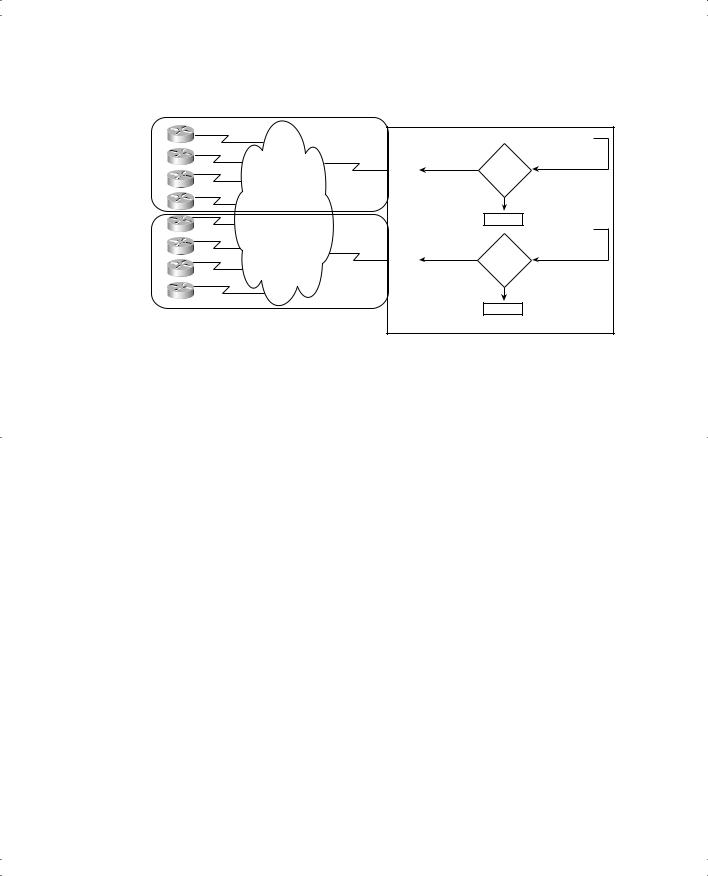
With Legacy DDR, there is no way to support a single set of remote sites through configuration using multiple different BRIs or PRIs in a single router. When you have multiple BRIs or PRIs, Legacy DDR allows you to dial only one set of sites using one interface and another set of sites with the other, as shown in Figure 10-8.

ISDN Configuration and Dial-on-Demand Routing 355
Figure 10-8 Legacy DDR with Two BRIs and Eight Remote Sites
A |
|
B |
|
C |
BRI0/0 |
Interesting |
|
|
PSTN |
D |
|
E |
|
F |
|
G |
BRI0/1 |
Interesting |
|
H |
|
Routes to A-D.
DDR 1
Boring
Discard
Routes to E-H.
DDR 2
Boring
Discard
Central Site Router
Figure 10-8 shows the logic that can be configured using Legacy DDR. The routes to four sites point out BRI0/0, and the routes to four other sites (E through H) point out BRI0/1. DDR uses a different dialer group on the two BRI interfaces, as noted in the diamonds with “DDR 1” (dialer group 1) and “DDR 2” (dialer group 2).
The problem with Legacy DDR in this case is that it cannot be configured to dial all eight sites using any available B channel on either BRI. Even if you configured two routes for each of the eight remote sites, one pointing out BRI0 and one out BRI1, Legacy DDR would still be confused as to which of the two BRI interfaces to use to dial a remote site. The root of the problem is that, with Legacy DDR, the static routes used by DDR can direct packets out a single physical BRI interface so that only a single BRI can be used to reach an individual remote site.
Dialer profiles overcome this problem with Legacy DDR using a slightly different style of DDR configuration. Dialer profiles pool the physical interfaces so that the router simply uses an available B channel on any of the BRIs or PRIs in the pool. Dialer profile configuration allows the Central Site router to dial any of the eight remote routers using either of the BRIs, as shown in Figure 10-9.

356 Chapter 10: ISDN and Dial-on-Demand Routing
Figure 10-9 Dialer Profiles: Pooling Multiple BRIs to Reach Eight Remote Sites
A
B |
Pool of BRI |
|
|
|
|
C |
BRI0/0 |
|
PSTN |
|
|
|
|
|
D |
Dialer |
|
|
|
|
E |
Interface |
Interesting |
|
|
|
F |
|
|
G |
BRI0/1 |
|
|
|
|
H |
|
|
Routes to A-H: Point Out Dialer Interface
DDR 1
Boring
Discard
DDR dialer profiles are a different style of configuration for DDR. This style of configuration moves most of the DDR interface configuration to a virtual interface called a dialer interface. Each physical BRI or PRI interface can be included in a pool of available physical ISDN interfaces. DDR logic relies on the routing of packets out the dialer interface. If a packet is interesting, DDR picks an interface from the pool over which to place the actual call.
The configuration for dialer profiles looks very similar to Legacy DDR configuration. Table 10-15 summarizes the differences.
Table 10-15 Summary of the New Configuration Needed for Dialer Profiles Versus Legacy DDR
Command |
Description |
Configuration Mode |
|
|
|
interface dialer x |
Creates the virtual dialer interface. |
Global |
|
|
|
dialer pool-member x |
Groups the physical ISDN interfaces |
Physical interface |
|
into a dialer pool. |
|
|
|
|
dialer pool x |
Tells the dialer interface which dialer |
Dialer interface |
|
pool to use. |
|
|
|
|
encapsulation ppp |
Configures PPP and authentication on |
Physical interface and |
|
the physical interfaces. |
dialer interface |
ppp authentication chap |
|
|
|
|
|
isdn spid1 spid |
Configures SPIDs as necessary. |
Physical interface |
isdn spid2 spid |
|
|
|
|
|
isdn switch-type type |
Configures the ISDN switch type. |
Global or physical |
|
|
interface |
|
|
|

ISDN Configuration and Dial-on-Demand Routing 357
A sample configuration can help, but first a few quick words about the generic configuration. You can migrate from a Legacy DDR configuration to dialer profiles by copying all the current BRI interface subcommands to the dialer interface, with the exception of the definitions of SPIDs and ISDN switch types. SPIDs and switch types are always specific to a particular physical interface. Also, IOS for some reason requires that you configure the encapsulation on both the dialer interface and the physical interfaces. Similarly, if you enable CHAP with the ppp authentication chap command, you need it on the dialer interface as well as on each physical ISDN interface. Other than those exceptions, you simply move the configuration from the physical interface to the dialer interface when migrating from Legacy DDR to dialer profiles.
The same familiar configuration from the SanFrancisco router, used with Legacy DDR, has been updated to use dialer profiles. Example 10-10 shows the complete configuration, with the new parts highlighted.
Example 10-10 SanFrancisco Configuration Migrated to Use Dialer Profiles and Two BRIs
ip route 172.16.3.0 255.255.255.0 172.16.2.1 ip route 172.16.4.0 255.255.255.0 172.16.2.3 ! Added usernames for CHAP support! username LosAngeles password Clark
username GothamCity password Bruce
!
isdn switch-type basic-ni1
!
access-list 101 permit tcp any host 172.16.3.1 eq 80 access-list 101 permit tcp any host 172.16.4.1 eq 21
!
dialer-list 2 protocol ip list 101
!
interface dialer 0
ip address 172.16.2.2 255.255.255.0 encapsulation ppp
ppp authentication chap dialer idle-timeout 300 dialer fast-idle 120
dialer map ip 172.16.2.1 broadcast name LosAngeles 14045551234
dialer map ip 172.16.2.3 broadcast speed 56 name GothamCity 1999999999901 dialer-group 2
dialer pool 3
!
interface bri0 encapsulation ppp
ppp authentication chap isdn spid1 555555111101 isdn spid2 555555222202 dialer pool-member 3
continues

358 Chapter 10: ISDN and Dial-on-Demand Routing
Example 10-10 SanFrancisco Configuration Migrated to Use Dialer Profiles and Two BRIs (Continued)
!
interface bri1 encapsulation ppp
ppp authentication chap isdn spid1 555555333301 isdn spid2 555555444402 dialer pool-member 3
!
router igrp 6 network 172.16.0.0
The following paragraphs take you through the configuration from top to bottom. First, the ip route commands are unchanged: They still refer to next-hop IP addresses in subnet 172.16.1.0/24. However, now the dialer interface, with address and mask of 172.16.1.2/24, is the implied outgoing interface.
Next, you see several items that are unchanged in both syntax and how they are used. The CHAP usernames and password come next, followed by the global isdn switch-type command. These work just as they always have. Likewise, the access-list commands define the interesting logic—with the same old parameters—and the dialer-list 2 command refers to those ACLs to define what is interesting and what is not.
The interface dialer 0 command comes next. It creates the virtual dialer interface. If you compare this example with Example 10-4, the Legacy DDR configuration, you will note that all the commands formerly found under BRI0 have been copied under the dialer interface, with the exception of SPIDs and switch-type commands.
The static routes now forward the packets out the dialer interface because now the dialer interface’s IP address is the same subnet as the destination IP address in the static route commands. However, the dialer interface itself cannot place a call, so the router notices the dialer pool 3 command under interface dialer 0. This tells the router to look for any ISDN interface in dialer pool 3 to actually place the call.
The two BRI interfaces come next. Each has its respective SPIDs configured. Also, each is placed in the same pool with the dialer pool-member 3 command. So both interfaces are available to the dialer interface for use to dial remote sites.
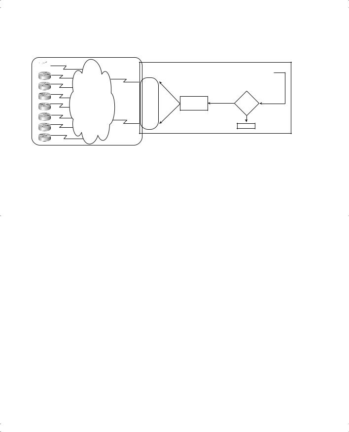
With DDR dialer profiles, you can configure many advanced features. For instance, Figure 10-10 shows the usage of multiple dialer interfaces along with some physical interfaces that are part of more than one pool.