


Scaling the IP Address Space for the Internet 265
3.The NAT router needs to allocate an IP address from the pool of valid inside global addresses. It picks the first one available (200.1.1.1 in this case) and adds it to the NAT table to complete the entry.
4.The NAT router translates the source IP address and forwards the packet.
The dynamic entry stays in the table as long as traffic flows occasionally. You can configure a timeout value that defines how long the router should wait, having not translated any packets with that address, before removing the dynamic entry. You can also manually clear the dynamic entries from the table using the clear ip nat translation * command.
NAT can be configured with more IP addresses in the inside local address list than in the inside global address pool. In the next section, you will learn about a feature called Port
Address Translation (PAT), which allows all flows from the inside hosts to be supported by
NAT, even when the inside global pool is smaller than the number of inside local addresses. However, without PAT, NAT can concurrently support only the number of hosts defined in the NAT pool.
When the number of registered public IP addresses is defined in the inside global address pool, as shown in Figure 8-4, the router allocates addresses from the pool until all are allocated. If a new packet arrives, and it needs a NAT entry, but all the pooled IP addresses are in use, the router simply discards the packet. The user must try again until a NAT entry times out, at which point the NAT function works for the next host that sends a packet. Essentially, the inside global pool of addresses needs to be as large as the maximum number of concurrent hosts that need to use the Internet at the same time—unless you use PAT.
Overloading NAT with Port Address Translation (PAT)
Some networks need to have most, if not all, IP hosts reach the Internet. If that network uses private IP addresses, the NAT router needs a very large set of registered IP addresses. With static NAT, for each private IP host that needs Internet access, you need a publicly registered IP address—completely defeating the advantage of using NAT. Dynamic NAT lessens the problem to some degree, but you might imagine that a large percentage of the IP hosts in a network will need Internet access throughout that company’s normal business hours—once again requiring a large number of registered IP addresses.
Overloading allows NAT to scale to support many clients with only a few public IP addresses. The key to understanding how overloading works is to recall how ports are used in TCP/IP. Figure 8-6 details an example that helps make the logic behind overloading more obvious.

266 Chapter 8: Advanced TCP/IP Topics
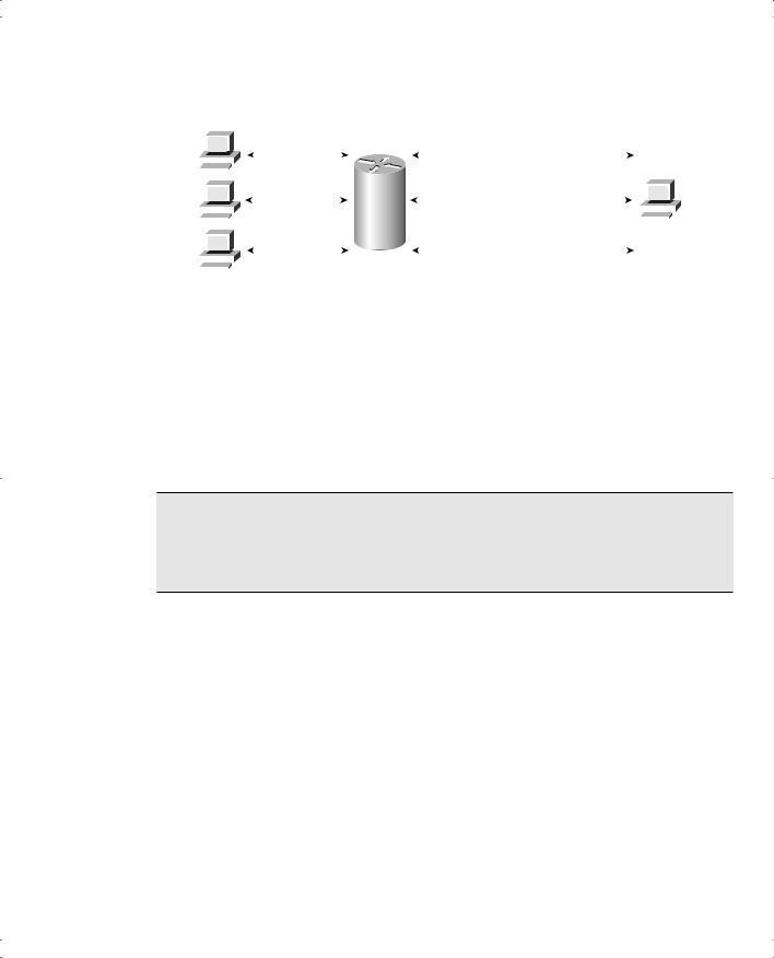
Figure 8-6 Three TCP Connections: From Three Different Hosts, and from One Host
Three Connections from Three PCs
10.1.1.1 |
|
|
|
|
10.1.1.1, Port 1024 |
|
170.1.1.1, Port 80 |
|||||||||
|
|
|
|
|
|
|
|
|
|
|
Server |
|||||
|
|
|
|
|
10.1.1.2, Port 1024 |
|
|
|
||||||||
|
|
|
|
|
|
|
|
|||||||||
|
|
|
|
|
|
|||||||||||
10.1.1.2 |
|
|
|
|
|
170.1.1.1, Port 80 |
|
|
|
|
|
|||||
|
|
|
|
|
|
|
||||||||||
|
|
|
|
|
|
|
|
|
|
|
|
|
|
|
|
|
|
|
|
|
|
|
|
|
Internet |
|
|
|
|
|
|
|
|
|
|
|
|
|
|
|
|
|
|
|
|
|
|
|
|
|
|
|
|
|
|
|
|
|
|
|
|
|
|
|
|
|
|
|
|
|
|
|
10.1.1.3, Port 1033 |
170.1.1.1 |
||||||||||
|
|
|
|
|
|
|||||||||||
10.1.1.3 |
|
|
|
|
|
170.1.1.1, Port 80 |
||||||||||
|
|
|
|
|
|
|
|
|
|
|
|
|
|
|
|
|
|
|
|
|
|
|
|
|
|
|
|
|
|
|
|
|
|
|
|
|
|
|
|
|
|
|
|
|
|
|
|
|
|
|
Three Connections from One PC
|
|
|
|
|
200.1.1.2, Port 1024 |
|
170.1.1.1, Port 80 |
||||||||||
|
|
|
|
|
|
|
|
|
|
|
|
Server |
|||||
|
|
|
|
|
|
|
|
|
|
|
|
||||||
200.1.1.2 |
|
|
|
|
200.1.1.2, Port 1025 |
|
170.1.1.1, Port 80 |
|
|
|
|
|
|||||
|
|
|
|
|
|
|
|||||||||||
|
|
|
|
|
|
|
|
|
|
|
|
|
|
|
|
|
|
|
|
|
|
|
|
|
|
Internet |
|
|
|
|
|
|
|
|
|
|
|
|
|
|
|
|
|
|
|
|
|
|
|
|
|
|
|
|
|
|
|
|
|
|
|
|
|
|
|
|
|
|
|
|
|
|
|
|
|
|
200.1.1.2, Port 1026 |
170.1.1.1 |
|||||||||||
|
|
|
|
|
|
||||||||||||
|
|
|
|
|
|
170.1.1.1, Port 80 |
|||||||||||
|
|
|
|
|
|
|
|
|
|
|
|
|
|
|
|
|
|
The top part of the figure shows a network with three different hosts connecting to a web server using TCP. The bottom half of the figure shows the same network later in the day, with three TCP connections from the same client. All six connections connect to the server IP address (170.1.1.1) and port (80, the well-known port for web services). In each case, the server differentiates between the various connections because their combined IP address and port numbers are unique.
NAT takes advantage of the fact that the server really doesn’t care if it has one connection each to three different hosts or three connections to a single host IP address. So, to support lots of inside local IP addresses with only a few inside global, publicly registered IP addresses,
NAT overload uses Port Address Translation (PAT). Instead of just translating the IP address, it also translates the port number. Figure 8-7 outlines the logic.
When NAT creates the dynamic mapping, it selects not only an inside global IP address but also a unique port number to use with that address. The NAT router keeps a NAT table entry for every unique combination of inside local IP address and port, with translation to the inside global address and a unique port number associated with the inside global address. And because the port number field has 16 bits, NAT overload can use more than 65,000 port numbers, allowing it to scale well without needing very many registered IP addresses—in many cases, needing only one.
Scaling the IP Address Space for the Internet 267
Figure 8-7 NAT Overload Using PAT
10.1.1.1 |
|
|
|
|
10.1.1.1, Port 1024 |
|
200.1.1.2, Port 1024 |
170.1.1.1, Port 80 |
||||||||||||||
|
|
|
|
|
|
|
|
|
|
|
|
|
|
|
|
|
Server |
|||||
|
|
|
|
|
10.1.1.2, Port 1024 |
|
200.1.1.2, Port 1025 |
|
|
|||||||||||||
|
|
|
|
|
|
|
|
|||||||||||||||
|
|
|
|
|
|
|||||||||||||||||
10.1.1.2 |
|
|
|
|
|
170.1.1.1, Port 80 |
|
|
|
|
|
|||||||||||
|
|
|
|
|
|
|||||||||||||||||
|
|
|
|
|
|
|
|
|
|
|
|
|
|
|
|
|
|
|
|
|
|
|
|
|
|
|
|
|
|
|
|
|
NAT |
|
|
|
|
|
|
|
|
||||
|
|
|
|
|
|
|
|
|
|
|
|
|
|
|
|
|
|
|
|
|
|
|
|
|
|
|
|
|
|
|
|
|
|
|
|
|
|
|
|
|
|
|
|
|
|
|
|
|
|
|
10.1.1.3, Port 1033 |
|
200.1.1.2, Port 1026 |
170.1.1.1 |
||||||||||||||
10.1.1.3 |
|
|
|
|
|
170.1.1.1, Port 80 |
||||||||||||||||
|
|
|
|
|
|
|
|
|
|
|
|
|
|
|
|
|
|
|
|
|
|
|
|
|
|
|
|
|
|
Dynamic NAT Table, With Overloading |
|
|
|
|
|
|
|
|
|||||||
|
|
|
|
|
|
|
|
|
|
|
|
|
|
|
||||||||
|
|
|
|
|
|
|
|
|
|
|
|
|
|
|
||||||||
|
|
|
|
|
|
|
|
Inside Local |
|
Inside Global |
|
|
|
|
|
|
|
|
|
|||
|
|
|
|
|
|
|
|
10.1.1.1:1024 |
|
200.1.1.2:1024 |
|
|
|
|
|
|
|
|
|
|||
|
|
|
|
|
|
|
|
|
|
|
|
|
|
|||||||||
|
|
|
|
|
|
|
|
10.1.1.2:1024 |
|
200.1.1.2:1025 |
|
|
|
|
|
|
|
|
|
|||
|
|
|
|
|
|
|
|
10.1.1.3:1033 |
|
200.1.1.2:1026 |
|
|
|
|
|
|
|
|
|
|||
|
|
|
|
|
|
|
|
|
|
|
|
|
|
|
|
|
|
|
|
|
|
|
Translating Overlapping Addresses
NAT also can be used when the private organization is not using private addressing but instead is using a network number registered to another company.
NOTE A client company of mine once did just that. The company was using a network number registered to Cabletron, which the company saw used in a presentation by an exCabletron employee who was working at 3COM. The 3COM employee explained IP addressing using the Cabletron registered network number because he was accustomed to it. My client liked the design and took him at his word—literally.
If one company inappropriately uses a network number that is registered appropriately to a different company, and they both connect to the Internet, NAT can be used to solve the problem. NAT translates both the source and the destination IP addresses in this case.
For example, consider Figure 8-8, in which Company A uses a network that is registered to Cisco (170.1.0.0).
With an overlapping address space, a client in Company A cannot send a packet to the legitimate IP host 170.1.1.1—or, if it did, the packet would never get to the real 170.1.1.1. Why? The routing tables inside the company (on the left) probably have a route matching 170.1.1.1 in its routing table. For host 170.1.1.10 in the figure, it is in the subnet in which the “private” 170.1.1.1 would reside, so host 170.1.1.10 would not even try to forward packets destined for 170.1.1.1 to a router. Instead, it would forward them directly to host 170.1.1.1, assuming it was on the same LAN!

268 Chapter 8: Advanced TCP/IP Topics
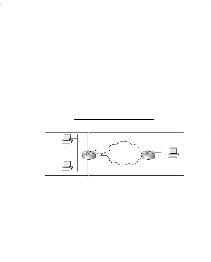
Figure 8-8 NAT IP Address Swapping: Unregistered Networks
Client
(Company A) Server
NAT
|
|
|
|
|
|
|
|
|
|
|
Private |
|
|
|
|
Internet |
|
|
|
|
|
|
|
|
||||||
|
|
|
|
|
|
|
|
|
|
|
|
|
|
|
|
|
|
|
|
|
|
|
|
|
|
|
|
|
|
|
|
|
|
|
|
|
|
|
|
|
|
|
|
|
|
|
|
|
|
|
|
|
|
|
|
|
|
|
|
||
170.1.1.10 |
|
|
|
|
|
|
|
|
|
|
|
www.cisco.com |
||||||||||||||||||
|
|
|
|
|
|
|
|
|
|
|
|
|
|
|
|
|
|
|
|
170.1.1.1 |
|
|
|
|||||||
|
|
|
|
Source |
Destination |
|
|
|
|
|
|
|
Source |
Destination |
||||||||||||||||
|
|
|
170.1.1.10 |
192.168.1.1 |
........ |
|
|
|
|
200.1.1.1 |
170.1.1.1 |
|
|
........ |
|
|
|
|
|
|
|
|||||||||
|
|
|
|
|
|
|
|
|
|
|
|
|
|
|
|
|
|
|
|
|
|
|
|
|
|
|
|
|
|
|
|
|
|
|
|
|
|
|
|
|
|
|
|
|
|
|
|
|
|
|
|
||||||||||
|
|
|
|
Source |
Destination |
|
|
|
|
|
|
|
Source |
Destination |
||||||||||||||||
|
192.168.1.1 |
170.1.1.10 |
........ |
|
|
|
|
170.1.1.1 |
200.1.1.1 |
|
|
........ |
|
|
|
|
|
|
|
|||||||||||
|
|
|
|
|
|
|
|
|
|
|
|
|
|
|
|
|
|
|
|
|
|
|
|
|
|
|
|
|
|
|
|
|
|
|
|
|
|
|
|
|
|
|
|
|
|
|
|
|
|
|
|
|
|
|
|
|
|
|
|
||
|
|
|
|
|
|
|
|
|
|
|
|
NAT Table After First Packet |
|
|
|
|
|
|
|
|
|
|
|
|||||||
|
|
|
|
|
|
|
|
|
|
|
|
|
|
|
|
|||||||||||||||
|
|
|
|
|
|
|
|
|
Inside Local |
|
Inside Global |
|
Outside Local |
Outside Global |
|
|
|
|
|
|
|
|||||||||
|
|
|
|
|
|
|
|
|
|
|
|
|
|
|
|
|
|
|||||||||||||
|
|
|
|
|
|
|
|
|
170.1.1.10 |
|
200.1.1.1 |
|
|
192.168.1.1 |
170.1.1.1 |
|
|
|
|
|
|
|
|
|
|
|||||
NAT can solve this problem, but both the source and the destination addresses must be changed as the packet passes through the NAT router. In Figure 8-8, notice that the original packet sent by the client has a destination address of 192.168.1.1. That address, called the outside local address, represents the registered IP address 170.1.1.1 on the left side of the network. “Outside” means that the address represents the host that physically sits in the “outside” part of the network. “Local” means that this address represents the host on the private side of the network.
As the packet passes through the NAT router (left to right), the source address is changed, just like in the previous example. However, the destination address is also changed—in this case, to 170.1.1.1. The destination address is also called the outside global address at this point, because it represents a host that is always physically on the outside network, and the address is the global, publicly registered IP address that can be routed through the Internet.
The NAT configuration includes a static mapping between the real IP address (outside global), 170.1.1.1, and the private IP address (outside local) used to represent it inside the private network—192.168.1.1.
Because the client initiates a connection to the server on the left, the NAT router not only must translate addresses, but it also must modify DNS responses. The client, for instance, performs a DNS request for www.cisco.com. When the DNS reply comes back (right to left) past the NAT router, NAT changes the DNS reply so that the client in the company thinks that www.cisco.com’s IP address is 192.168.1.1.
Today, given a choice, companies tend to simply use private addressing to avoid the need to translate both IP addresses in each packet. Also, the NAT router needs a static entry for every server in the overlapped network number—a potentially painstaking task. By using private addresses, you can use NAT to connect the network to the Internet, reduce the number of registered IP addresses needed, and have to perform only the NAT function for the private address in each packet.
Scaling the IP Address Space for the Internet 269
Table 8-4 summarizes the use of NAT terminology in Figure 8-8.
Table 8-4 NAT Addressing Terms as Used in Figure 8-8
Term |
Value in Figure 8-8 |
|
|
Inside local |
170.1.1.10 |
|
|
Inside global |
200.1.1.1 |
|
|
Outside global |
170.1.1.1 |
|
|
Outside local |
192.168.1.1 |
|
|
NAT Configuration
In this section, you will read about how to configure several variations of NAT, along with the show and debug commands used to troubleshoot NAT. Table 8-5 lists the NAT configuration commands. Table 8-6 lists the EXEC commands related to NAT.
Table 8-5 NAT Configuration Commands
Command |
Configuration Mode |
|
|
ip nat {inside | outside} |
Interface subcommand |
|
|
ip nat inside source {list {access-list-number | access-list-name} | |
Global command |
route-map name} {interface type number | pool pool-name} |
|
[overload] |
|
|
|
ip nat inside destination list {access-list-number | name} pool name |
Global command |
|
|
ip nat outside source {list {access-list-number | access-list-name} | |
Global command |
route-map name} pool pool-name [add-route] |
|
|
|
ip nat pool name start-ip end-ip {netmask netmask | prefix-length |
Global command |
prefix-length} [type rotary] |
|
|
|
Table 8-6 NAT EXEC Commands
Command |
Description |
|
|
show ip nat statistics |
Lists counters for packets and NAT table |
|
entries, as well as basic configuration |
|
information. |
|
|
show ip nat translations [verbose] |
Displays the NAT table. |
|
|
clear ip nat translation {* | [inside global-ip |
Clears all or some of the dynamic entries in |
local-ip] [outside local-ip global-ip]} |
the NAT table, depending on which |
|
parameters are used. |
|
|
clear ip nat translation protocol inside global-ip |
Clears some of the dynamic entries in the |
global-port local-ip local-port [outside local-ip |
NAT table, depending on which |
global-ip] |
parameters are used. |
|
|
debug ip nat |
Issues a log message describing each packet |
|
whose IP address is translated with NAT. |
|
|

270 Chapter 8: Advanced TCP/IP Topics
Static NAT Configuration
Static NAT configuration, as compared to the other variations of NAT, requires the fewest configuration steps. Each static mapping between a local (private) address and a global (public) address must be configured. Then, each interface needs to be identified as either an inside or outside interface.
Figure 8-9 shows the familiar network used in the description of static NAT earlier in this chapter.
Figure 8-9 NAT IP Address Swapping: Unregistered Networks
Registered Network: 200.1.1.0
FredCo |
200.1.1.251 |
200.1.1.252 |
|
|
|
|
|
|
|
|||||||||||
|
|
|
|
|
|
Server |
||||||||||||||
|
|
|
|
|
|
|
|
|
|
|
|
|
|
|
||||||
|
|
|
|
|
|
|
|
|
|
|
|
|
|
|
||||||
|
|
|
|
|
|
|
|
|
|
|
|
|
|
|
||||||
10.1.1.1 |
|
|
|
|
|
|
||||||||||||||
|
|
|
|
|
|
|
|
|
|
|
|
|||||||||
|
|
|
|
|
|
|
|
|
|
|
|
|
Internet |
|
|
|
|
|
|
|
|
|
|
|
|
|
|
|
|
NAT S0/0 |
|
|
|
|
|
|
|
|
|||
|
|
|
|
|
|
|
|
|
|
|
|
|
|
|
|
|
||||
|
|
|
|
|
|
|
|
|
|
|
|
|
|
|
|
|
|
|||
|
|
|
|
|
|
|
|
E0/0 |
170.1.1.1 |
|||||||||||
|
|
|
|
|
|
|
|
|
|
|
|
|
|
|
|
|
|
|||
|
|
|
|
|
|
|
|
|
|
|
|
|
|
|
|
|
|
|
|
|
|
|
|
|
|
|
|
|
|
|
|
|
|
|
|
|
|
|
|
|
|
10.1.1.2 |
|
|
|
|
|
|
|
|
|
|
|
|
||||||||
Inside |
|
|
|
|
|
|
|
Outside |
||||||||||||
|
|
|
|
|
|
|
|
|
|
|||||||||||
|
|
|
|
Inside Local |
|
Inside Global |
|
|
|
|
|
|
|
|
||||||
|
|
|
|
10.1.1.1 |
|
200.1.1.1 |
|
|
|
|
|
|
|
|
|
|||||
|
10.1.1.2 |
|
200.1.1.2 |
|
|
|
|
|
|
|
|
|
||||||||
|
|
|
|
|
|
|
|
|
|
|
|
|
|
|
|
|
|
|
|
|
In Figure 8-9, you can see that FredCo has obtained Class C network 200.1.1.0 as a registered network number. That entire network, with mask 255.255.255.0, is configured on the serial link between FredCo and the Internet. With a point-to-point serial link, only two of the 254 valid IP addresses in that network are consumed, leaving 252 addresses for use with static NAT. Example 8-1 lists the NAT configuration, using 200.1.1.1 and 200.1.1.2 for the two static NAT mappings.
Example 8-1 Static NAT Configuration
NAT# show running-config
!
! Lines omitted for brevity
!
interface Ethernet0/0
ip address 10.1.1.3 255.255.255.0
ip nat inside

Scaling the IP Address Space for the Internet 271
Example 8-1 Static NAT Configuration (Continued)
!
interface Serial0/0
ip address 200.1.1.251 255.255.255.0 ip nat outside
!
ip nat inside source static 10.1.1.2 200.1.1.2 ip nat inside source static 10.1.1.1 200.1.1.1
NAT# show ip nat translations |
|
|
|||||
Pro |
Inside global |
|
Inside local |
Outside local |
Outside global |
||
--- |
|
200.1.1.1 |
|
10.1.1.1 |
|
--- |
--- |
|
|
|
|||||
--- |
|
200.1.1.2 |
|
10.1.1.2 |
|
--- |
--- |
|
|
|
|
|
|
|
|
NAT# show ip nat statistics
Total active translations: 2 (2 static, 0 dynamic; 0 extended)
Outside interfaces:
Serial0/0
Inside interfaces:
Ethernet0/0
Hits: 100 Misses: 0
Expired translations: 0
Dynamic mappings:
The static mappings are created using the ip nat inside source static command. The inside keyword means that NAT translates addresses for hosts on the inside part of the network. The source keyword means that NAT translates the source IP address of packets coming into its inside interfaces. static means that the parameters define a static entry, which should never be removed from the NAT table due to timeout. Because the design calls for two hosts, 10.1.1.1 and 10.1.1.2, to have Internet access, two ip nat inside commands are needed.
After creating the static NAT entries, the router needs to know which interfaces are “inside” and which are “outside.” The ip nat inside and ip nat outside interface subcommands identify each interface appropriately.
A couple of show commands list the most important information about NAT. The show ip nat translations command lists the two static NAT entries created in the configuration. The show ip nat statistics command lists statistics, listing things such as the number of currently active translation table entries. The statistics also include the number of hits, which increments for every packet for which NAT must translate addresses.

272 Chapter 8: Advanced TCP/IP Topics
Dynamic NAT Configuration
As you might imagine, dynamic NAT configuration differs in some ways from static NAT, but it has some similarities as well. Dynamic NAT still requires that each interface be identified as either an inside or outside interface. However, the static mapping is no longer required. Dynamic NAT uses the ip nat inside command to identify which inside local (private) IP addresses need to have their addresses translated. With the ip nat pool command, dynamic NAT defines the set of IP addresses used as inside global (public) addresses.
The next example uses the same network topology as the previous example (see Figure 8-9). In this case, the same two inside local addresses, 10.1.1.1 and 10.1.1.2, need translation. The same inside global addresses used in the static mappings in the previous example, 200.1.1.1 and 200.1.1.2, are instead placed in a pool of dynamically assignable inside global addresses.
Example 8-2 shows the configuration, as well as some show commands.
Example 8-2 Dynamic NAT Configuration
NAT# show running-config
!
! Lines omitted for brevity
!
interface Ethernet0/0
ip address 10.1.1.3 255.255.255.0 ip nat inside
!
interface Serial0/0
ip address 200.1.1.251 255.255.255.0 ip nat outside
!
ip nat pool fred 200.1.1.1 200.1.1.2 netmask 255.255.255.252 ip nat inside source list 1 pool fred
!
access-list 1 permit 10.1.1.2 access-list 1 permit 10.1.1.1
!
NAT# show ip nat translations
NAT# show ip nat statistics
Total active translations: 0 (0 static, 0 dynamic; 0 extended)
Outside interfaces:
Serial0/0
Inside interfaces:
Ethernet0/0
Hits: 0 Misses: 0
Expired translations: 0
Dynamic mappings:
-- Inside Source
access-list 1 pool fred refcount 0


274 Chapter 8: Advanced TCP/IP Topics
command lists the first and last numbers in a range of inside global addresses. For instance, if the pool needed ten addresses, the command might have listed 200.1.1.1 and 200.1.1.10. This command also lists a subnet mask, but it has no real effect, because the first and last IP addresses are listed.
Like static NAT, dynamic NAT uses the ip nat inside source command. Unlike static NAT, the dynamic NAT version of this command refers to the name of the NAT pool it wants to use for inside global addresses—in this case, fred. It also refers to an IP Access Control List (ACL), which defines the matching logic for inside local IP addresses. The command ip nat inside source list 1 pool fred maps between hosts matched by ACL 1 and the pool called fred, which was created by the ip nat pool fred command.
NOTE Chapter 12, “IP Access Control List Security,” covers the details of how IP ACLs work. For now, just know that ACL 1 in this example matches packets whose source IP addresses are either 10.1.1.1 or 10.1.1.2 and does not match any other packets.
Example 8-2 contains several show commands. Several instances of show command output change based on what has happened on the two client host computers. Comments describe what has been done on the two hosts that causes a change in the output of the show commands.
First, the show ip nat translations and show ip nat statistics commands display either nothing or minimal configuration information. Because neither host 10.1.1.1 nor 10.1.1.2 has sent any packets, NAT has not created any dynamic entries in the NAT table or translated addresses in any packets.
After the Telnet from 10.1.1.1 to 170.1.1.1, the statistics show that a dynamic NAT entry has been added. The NAT table shows a single entry, mapping 10.1.1.1 to 200.1.1.1. The NAT table entry times out after a period of inactivity. However, to force the entry out of the table, the clear ip nat translation command can be used. As shown in Table 8-6, this command has several variations. Example 8-2 uses the brute-force option—clear ip nat translation *. With this command, all dynamic NAT entries are removed.
After clearing the NAT entry, host 10.1.1.2 Telnets to 170.1.1.1. The show ip nat translations command now shows a mapping between 10.1.1.2 and 200.1.1.1. Because 200.1.1.1 is no longer allocated in the NAT table, the NAT router can allocate it for the next NAT request.
Finally, at the end of Example 8-2, you see the output from the debug ip nat command. This command causes the router to issue a message every time a packet has its address translated for NAT. You generate the output results by entering a few lines from the Telnet connection

276 Chapter 8: Advanced TCP/IP Topics
Telnet connection, causing three dynamic NAT entries, each using inside global address 200.1.1.249, but each with a unique port number.
Example 8-3 NAT Overload Configuration
NAT# show running-config
!
! Lines Omitted for Brevity
!
interface Ethernet0/0
ip address 10.1.1.3 255.255.255.0 ip nat inside
!
interface Serial0/0
ip address 200.1.1.249 255.255.255.252 ip nat outside
!
ip nat inside source list 1 interface Serial0/0 overload
!
access-list 1 permit 10.1.1.2 access-list 1 permit 10.1.1.1
!
NAT# show ip nat translations |
|
|
|
Pro Inside global |
Inside local |
Outside local |
Outside global |
|
|
|
|
tcp 200.1.1.249:3212 |
10.1.1.1:3212 |
170.1.1.1:23 |
170.1.1.1:23 |
tcp 200.1.1.249:3213 |
10.1.1.1:3213 |
170.1.1.1:23 |
170.1.1.1:23 |
tcp 200.1.1.249:38913 |
10.1.1.2:38913 |
170.1.1.1:23 |
170.1.1.1:23 |
|
|
|
|
NAT# show ip nat statistics
Total active translations: 3 (0 static, 3 dynamic; 3 extended)
Outside interfaces:
Serial0/0
Inside interfaces:
Ethernet0/0
Hits: 103 Misses: 3
Expired translations: 0
Dynamic mappings:
-- Inside Source
access-list 1 interface Serial0/0 refcount 3
The ip nat inside source list 1 interface serial 0/0 overload command has several parameters, but if you understand the dynamic NAT configuration, the new parameters shouldn’t be too hard to grasp. The list 1 parameter means the same thing as it does for dynamic NAT: Inside local IP addresses matching ACL 1 have their addresses translated. The interface serial 0/0 parameter means that the only inside global IP address available is the IP address of the NAT router’s interface serial 0/0. Finally, the overload parameter means that overload is enabled. Without this parameter, the router does not perform overload, just dynamic NAT.