

72 Chapter 3: Virtual LANs and Trunking
Figure 3-1 Network with Two VLANs Using One Switch
Dino
VLAN 1
 Fred
Fred
 Wilma
Wilma
VLAN 2
Yes, the concepts behind VLANs are that simple. The use of VLANs does introduce a couple of other concepts you should know. Next you will learn about VLAN trunking, VLAN Trunking Protocol, and some issues related to Layer 3 protocols when using VLANs.
Trunking with ISL and 802.1Q
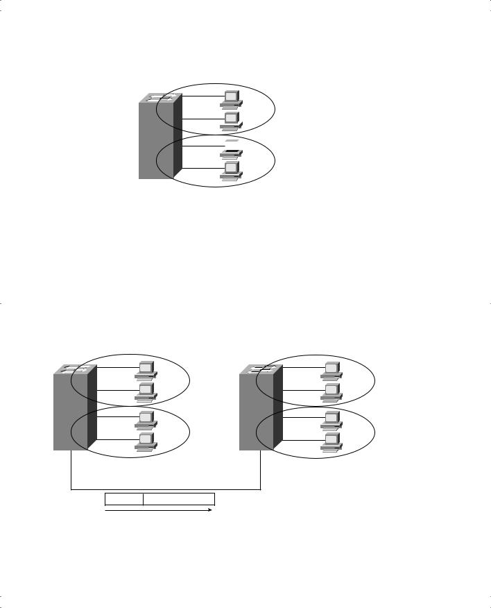
When using VLANs in networks that have multiple interconnected switches, you need to use VLAN trunking between the switches. With VLAN trunking, the switches tag each frame sent between switches so that the receiving switch knows to what VLAN the frame belongs. Figure 3-2 outlines the basic idea.
Figure 3-2 VLAN Trunking Between Two Switches |
|
|
|
||
Switch 1 |
0/1 |
VLAN 1 |
Switch 2 |
0/1 |
VLAN 1 |
|
0/2 |
|
|
0/2 |
|
|
0/5 |
VLAN 2 |
|
0/5 |
VLAN 2 |
0/23 |
|
|
0/13 |
|
|
Trunk
VLAN ID Ethernet Frame
With trunking, you can support multiple VLANs that have members on more than one switch. For instance, when Switch 1 receives a broadcast from a device in VLAN 1, it needs to forward the broadcast to Switch 2. Before sending the frame, Switch1 adds another header
Trunking with ISL and 802.1Q 73
to the original Ethernet frame; that new header has the VLAN number in it. When Switch 2 receives the frame, it sees that the frame was from a device in VLAN1, so Switch2 knows that it should only forward the broadcast out its own interfaces in VLAN1.
Cisco switches support two different trunking protocols—Inter-Switch Link (ISL) and IEEE 802.1Q. Both provide basic trunking, as shown in Figure 3-2. They do have some differences, as discussed next.
ISL
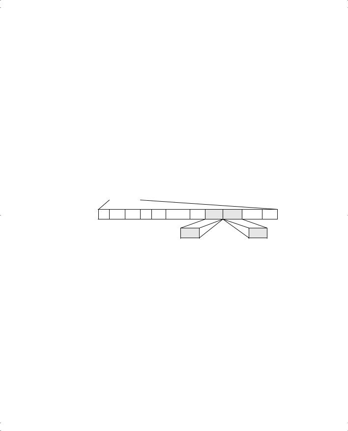
Cisco created ISL before the IEEE standardized a trunking protocol. Because ISL is Ciscoproprietary, it can be used only between two Cisco switches. ISL fully encapsulates each original Ethernet frame in an ISL header and trailer. The original Ethernet frame inside the ISL header and trailer remains unchanged. Figure 3-3 shows the framing for ISL.
Figure 3-3 ISL Header
ISL Header |
Encapsulated Ethernet Frame |
CRC |
26 bytes |
|
4 bytes |
DA Type User SA LEN AAAA03 HSA VLAN BPDU INDEX RES
VLAN |
BPDU |
The ISL header includes several fields, but most importantly, the ISL header VLAN field provides a place to encode the VLAN number. By tagging a frame with the correct VLAN number inside the header, the sending switch can ensure that the receiving switch knows to which VLAN the encapsulated frame belongs. Also, the source and destination addresses in the ISL header use MAC addresses of the sending and receiving switch, as opposed to the devices that actually sent the original frame. Other than that, the details of the ISL header are not that important.
802.1Q
The IEEE standardizes many of the protocols relating to LANs today, and VLAN trunking is no exception. After Cisco created ISL, the IEEE completed work on the 802.1Q standard, which defines a different way to do trunking.
74 Chapter 3: Virtual LANs and Trunking
802.1Q uses a different style of header than does ISL to tag frames with a VLAN number. In fact, 802.1Q does not actually encapsulate the original frame. Rather, it adds an extra 4-byte header to the original Ethernet header. That additional header includes a field with which to identify the VLAN number. Because the original header has been changed, 802.1Q encapsulation forces a recalculation of the original FCS field in the Ethernet trailer, because the FCS is based on the contents of the entire frame. Figure 3-4 shows the 802.1Q header and framing of the revised Ethernet header.
Figure 3-4 802.1Q Trunking Header
Dest |
Src |
Len/Etype |
Data |
FCS |
Original |
|
|
Frame |
|
|
|||||
|
|
|
|
|
|
|
|
Dest |
Src |
Etype Tag |
Len/Etype |
|
Data |
FCS |
Tagged |
|
Frame |
||||||
|
|
|
|
|
|
|
Priority VLAN-ID
ISL and 802.1Q Compared
Both ISL and 802.1Q provide trunking. The header used by each varies, and only ISL actually encapsulates the original frame, but both allow the use of a 12-bit-long VLAN ID field. So, either works fine, and both support the same number of VLANs because both use a 12-bit VLAN Number field.
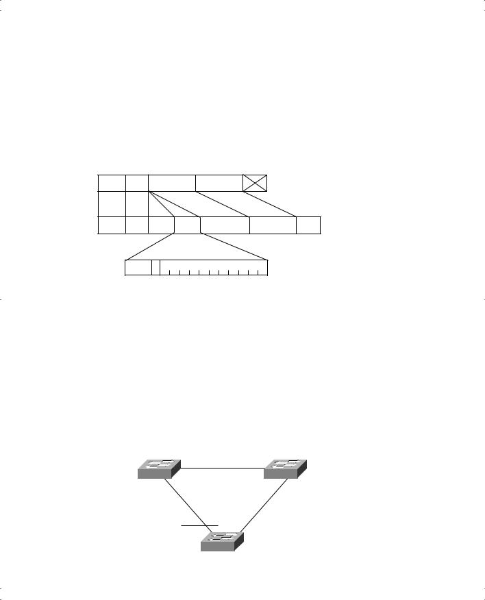
ISL and 802.1Q both support a separate instance of spanning tree for each VLAN. ISL supported this feature much earlier than did 802.1Q, so in years past, one of the stated differences between the two trunking protocols was that 802.1Q did not support multiple spanning trees. To appreciate the benefits of multiple spanning trees, examine Figure 3-5, which shows a simple network with two VLANs and three interconnected switches.
Figure 3-5 ISL Per-VLAN Spanning Tree (PVST)
SW1 |
SW2 |
Blocking — VLAN 2 Blocking — VLAN 1
SW3

Trunking with ISL and 802.1Q 75
You can tune STP parameters in each VLAN so that when all links are up, different interfaces block in different spanning trees. In the figure, only one of the six switch interfaces connecting the switches needs to block to prevent loops. STP can be configured so that VLAN 1 and VLAN 2 block different interfaces on SW3 in this example. So, SW3 actually uses the available bandwidth on each of its links to the other switches, because traffic in VLAN 1 uses the link to SW1, and traffic in VLAN 2 uses the link to SW2. Of course, if a link fails when you use ISL, both STP instances can converge so that a path is still available.
Cisco provides a variety of STP tools to accommodate multiple spanning trees. ISL uses a Cisco-proprietary feature called Per-VLAN Spanning Tree (PVST+) to support multiple spanning trees. 802.1Q did not originally support multiple spanning trees, but it can by using a couple other protocols. Cisco’s proprietary PVST+ allows multiple STP instances over
802.1Q trunks. Also, the IEEE has completed a new specification called 802.1S that adds to the 802.1Q specification, allowing multiple spanning trees. In addition to these protocols, Cisco supports other proprietary variations.
A key difference between ISL and 802.1Q relates to a feature called the native VLAN. 802.1Q defines one VLAN on each trunk as the native VLAN; by default, this is VLAN 1. By definition, 802.1Q simply does not encapsulate frames in the native VLAN when sending the frames over the trunk. When the switch on the other side of the link receives a frame in the native VLAN, it notices the lack of an 802.1Q header and knows that the frame is part of the native VLAN.
Native VLANs play a very important role from a practical perspective. Imagine that you have many PCs connected to some switch ports, and those PCs do not understand 802.1Q. You also plan to install IP phones near those PCs. IP phones have a built-in switch so that you can connect the phone to the Ethernet cable from the switch and then connect the phone to a PC. The phone understands 802.1Q, so you can put the phone in one VLAN and the PC in another. You can configure all those ports for 802.1Q, placing the PCs in the native VLAN. They work fine when connected directly to the switch, because the switch does not use any encapsulation for the native VLAN. When you install an IP phone between the switch and the PC, the phone can understand the 802.1Q headers and can send and receive traffic to and from the switch. The phone can just pass the native VLAN traffic between the PC and the switch.
ISL does not use a concept like native VLAN. All frames from all VLANs have an ISL header for transmission across an ISL trunk.