


388 Chapter 11: Frame Relay
The remaining examples in this chapter use global addressing in any planning diagrams unless otherwise stated. One practical way to determine whether the diagram lists the local DLCIs or the global DLCI convention is this: If two VCs terminate at the same DTE, and a single DLCI is shown, it probably represents the global DLCI convention. If one DLCI is shown per VC, local DLCI addressing is depicted.
Network Layer Concerns with Frame Relay
Most of the important Frame Relay concepts have been covered. First, the routers (DTEs) connect to the Frame Relay switches (DCEs) over an access link, which is a leased line between the router and the switch. The LMI protocol is used to manage the access link, and the LMI type must match between the router and the local switch. The routers agree to the style of encapsulation used. The single DLCI field in the Frame Relay header identifies the VC used to deliver the frame. The DLCI is used like a destination address when the frame is being sent and like a source address as the frame is received. The switches actually swap the DLCI in transit.
Frame Relay networks have both similarities and differences as compared to LAN and point- to-point WAN links. These differences introduce some additional considerations for passing Layer 3 packets across a Frame Relay network. You need to concern yourself with a couple of key issues relating to Layer 3 flows over Frame Relay:
■Choices for Layer 3 addresses on Frame Relay interfaces
■Broadcast handling
The following sections cover these issues in depth.
Layer 3 Addressing with Frame Relay
Cisco’s Frame Relay implementation defines three different options for assigning subnets and IP addresses on Frame Relay interfaces:
■One subnet containing all Frame Relay DTEs
■One subnet per VC
■A hybrid of the first two options
Frame Relay Layer 3 Addressing: One Subnet Containing All Frame Relay DTEs
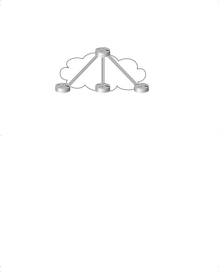
Figure 11-11 shows the first alternative, which is to use a single subnet for the Frame Relay network. The figure shows a fully meshed Frame Relay network because the single-subnet option is typically used when a full mesh of VCs exists. In a full mesh, each router has a VC to every other router, meaning that each router can send frames directly to every other router—which more closely equates to how a LAN works. So, a single subnet can be used for all the routers’ Frame Relay interfaces, as configured on the routers’ serial interfaces. Table 11-6 summarizes the addresses used in Figure 11-11.
Frame Relay Protocols 389
Figure 11-11 Full Mesh with IP Addresses
|
|
|
|
|
|
|
Subnet |
|
|
|
|
||
|
|
|
|
199.1.10.0/24 |
|
|
|
|
|
||||
|
|
|
|
|
|
|
|
|
|
|
|
|
|
|
|
|
|
|
|
|
|
Mayberry |
|||||
|
|
|
|
|
|
|
|
||||||
|
|
|
|
|
|
|
|
|
|
199.1.1.1 |
|
||
|
|
|
|
|
|
|
s0 |
|
|
|
|
||
|
|
|
|
|
|
|
Frame Relay |
|
|
|
|
||
199.1.1.2 |
|
|
|
Full Mesh |
199.1.1.3 |
|
|||||||
|
|
|
|
|
s0 |
s0 |
|||||||
|
Mount Pilot |
|
|
|
|
|
|
|
|
Raleigh |
|||
|
|
|
|
|
|
|
|
||||||
|
|
|
|
|
|
|
|
||||||
|
|
|
|
|
|
|
|
|
|
||||
|
|
Subnet |
|
Subnet |
|||||||||
199.1.11.0/24 |
|
|
|
|
199.1.12.0/24 |
|
|||||||
Table 11-6 IP Addresses with No Subinterfaces |
|
|
|
|
|||||||||
|
|
|
|
|
|
|
|
|
|
|
|
|
|
|
Router |
|
IP Address of Frame Relay Interface |
||||||||||
|
|
|
|
|
|
|
|
|
|
|
|
|
|
|
Mayberry |
199.1.1.1 |
|
|
|
|
|
|
|||||
|
|
|
|
|
|
|
|
|
|
|
|
|
|
|
Mount Pilot |
199.1.1.2 |
|
|
|
|
|
|
|||||
|
|
|
|
|
|
|
|
|
|
|
|
|
|
|
Raleigh |
199.1.1.3 |
|
|
|
|
|
|
|||||
|
|
|
|
|
|
|
|
|
|
|
|
|
|
The single-subnet alternative is straightforward, and it conserves your IP address space. It also looks like what you are used to with LANs, which makes it easier to conceptualize. Unfortunately, most companies build partial-mesh Frame Relay networks, and the singlesubnet option has some deficiencies when the network is a partial mesh.
Frame Relay Layer 3 Addressing: One Subnet Per VC
The second IP addressing alternative, the single-subnet-per-VC alternative, works better with a partially meshed Frame Relay network, as shown in Figure 11-12. Boston cannot forward frames directly to Charlotte, because no VC is defined between the two. This is a more typical Frame Relay network, because most organizations with many sites tend to group applications on servers at a few centralized locations, and most of the traffic is between each remote site and those servers.
Frame Relay Protocols 391
NOTE The example uses IP address prefixes of /24 to keep the math simple. In production networks, point-to-point subinterfaces typically use a prefix of /30 (mask 255.255.255.252), because that allows for only two valid IP addresses—the exact number needed on a point-to-point subinterface. Of course, using different masks in the same network means your routing protocol must also support VLSM.
Frame Relay Layer 3 Addressing: Hybrid Approach
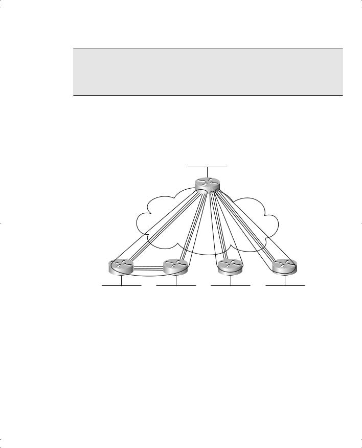
The third alternative of Layer 3 addressing is a hybrid of the first two alternatives. Consider Figure 11-13, which shows a trio of routers with VCs between each of them, as well as two other VCs to remote sites.
Figure 11-13 Hybrid of Full and Partial Mesh
DLCI 501
A
|
Subnet 1 |
|
|
|
|
|
Subnet 2 |
|
Subnet 3 |
|
|
|
|
|
DLCI 502 |
DLCI 503 |
DLCI 504 |
DLCI 505 |
|
|
|
C |
D |
E |
|
|
|
|
|
|
B |
|
|
|
Two options exist for Layer 3 addressing in this case. The first is to treat each VC as a separate Layer 3 group. In this case, five subnets are needed for the Frame Relay network.
However, Routers A, B, and C create a smaller full mesh between each other. This allows Routers A, B, and C to use one subnet. The other two VCs—one between Routers A and D and one between Routers A and E—are treated as two separate Layer 3 groups. The result is a total of three subnets.
To accomplish either style of Layer 3 addressing in this third and final case, subinterfaces are used. Point-to-point subinterfaces are used when a single VC is considered to be all that is in the group—for instance, between Routers A and D and between Routers A and E. Multipoint subinterfaces are used when more than two routers are considered to be in the same group— for instance, with Routers A, B, and C.