376 Chapter 11: Frame Relay
Foundation Topics
Frame Relay Protocols
If you’re using both books, in Chapter 4, “Fundamentals of WANs,” of CCNA INTRO Exam Certification Guide, you read about the basics of Frame Relay. This chapter begins with a brief review of those concepts, and then it dives into the details of Frame Relay protocols and concepts. This chapter ends with coverage of Frame Relay configuration.
Frame Relay networks provide more features and benefits than simple point-to-point WAN links, but to do that, Frame Relay protocols are more detailed. For example, Frame Relay networks are multiaccess networks, which means that more than two devices can attach to the network, similar to LANs. Unlike LANs, you cannot send a data link layer broadcast over Frame Relay. Therefore, Frame Relay networks are called nonbroadcast multiaccess (NBMA) networks. Also, because Frame Relay is multiaccess, it requires the use of an address that identifies to which remote router each frame is addressed.
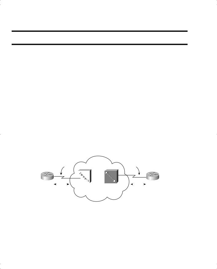
Figure 11-1 outlines the basic physical topology and related terminology in a Frame Relay network.
Figure 11-1 Frame Relay Components
|
|
Access |
|
Frame |
|
Access |
|||
|
|
|
Relay |
|
|||||
|
|
Link |
DCE |
DCE |
Link |
||||
|
|
|
|||||||
DTE |
|
|
|
|
|
|
DTE |
||
|
|
|
|
|
|
|
|
||
R1 |
|
|
|
|
|
|
|
|
R2 |
|
|
|
Frame |
|
Frame |
|
|
||
|
|
LMI |
|
|
LMI |
||||
|
|
Relay |
|
Relay |
|
||||
|
Messages |
|
Messages |
||||||
|
Switch |
|
Switch |
||||||
|
|
|
|
|
|
|
|
||
Figure 11-1 shows the most basic components of a Frame Relay network. A leased line is installed between the router and a nearby Frame Relay switch; this link is called the access link. To ensure that the link is working, the device outside the Frame Relay network, called the data terminal equipment (DTE), exchanges regular messages with the Frame Relay switch. These keepalive messages, along with other messages, are defined by the Frame Relay Local Management Interface (LMI) protocol. The routers are considered DTE, and the Frame Relay switches are data communications equipment (DCE).


378 Chapter 11: Frame Relay
Table 11-2 |
Frame Relay Terms and Concepts (Continued) |
|
|
|
|
|
Term |
Description |
|
|
|
|
Data communications equipment (DCE) |
Frame Relay switches are DCE devices. DCEs are |
|
|
also known as data circuit-terminating equipment. |
|
|
DCEs are typically in the service provider’s |
|
|
network. |
|
|
|
|
Access link |
The leased line between the DTE and DCE. |
|
|
|
|
Access rate (AR) |
The speed at which the access link is clocked. This |
|
|
choice affects the connection’s price. |
|
|
|
|
Data-link connection identifier (DLCI) |
A Frame Relay address used in Frame Relay |
|
|
headers to identify the VC. |
|
|
|
|
Nonbroadcast multiaccess (NBMA) |
A network in which broadcasts are not supported, |
|
|
but more than two devices can be connected. |
|
|
|
|
Local Management Interface (LMI) |
The protocol used between a DCE and DTE to |
|
|
manage the connection. Signaling messages for |
|
|
SVCs, PVC status messages, and keepalives are all |
|
|
LMI messages. |
|
|
|
Frame Relay Standards
The definitions for Frame Relay are contained in documents from the International Telecommunications Union (ITU) and the American National Standards Institute (ANSI). The Frame Relay Forum (www.frforum.com), a vendor consortium, also defines several Frame Relay specifications, many of which predate the original ITU and ANSI specifications, with the ITU and ANSI picking up many of the forum’s standards. Table 11-3 lists the most important of these specifications.
Table 11-3 Frame Relay Protocol Specifications
What the Specification Defines |
ITU Document |
ANSI Document |
|
|
|
Data-link specifications, including LAPF header/ |
Q.922 Annex A |
T1.618 |
trailer |
(Q.922-A) |
|
|
|
|
PVC management, LMI |
Q.933 Annex A |
T1.617 Annex D |
|
(Q.933-A) |
(T1.617-D) |
|
|
|
SVC signaling |
Q.933 |
T1.617 |
|
|
|
Multiprotocol encapsulation (originated in RFC |
Q.933 Annex E |
T1.617 Annex F |
1490/2427) |
(Q.933-E) |
(T1.617-F) |
|
|
|
Frame Relay Protocols 379
Virtual Circuits
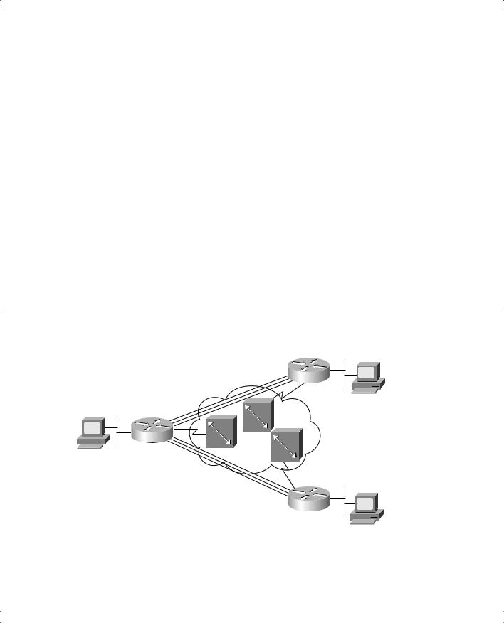
Frame Relay provides significant advantages over simply using point-to-point leased lines. The primary advantage has to do with virtual circuits. Consider Figure 11-3, which is a typical Frame Relay network with three sites.
Figure 11-3 Typical Frame Relay Network with Three Sites
Larry
R2
Server1
R1
Bob
R3
A virtual circuit defines a logical path between two Frame Relay DTEs. The term virtual circuit describes the concept well. It acts like a point-to-point circuit, providing the ability to send data between two endpoints over a WAN. There is no physical circuit directly between the two endpoints, so it’s virtual. For example, R1 terminates two VCs—one whose other endpoint is R2, and one whose other endpoint is R3. R1 can send traffic directly to either of the other two routers by sending it over the appropriate VC. R1 has only one physical access link to the Frame Relay network.
VCs share the access link and the Frame Relay network. For example, both VCs terminating at R1 use the same access link. In fact, many customers share the same Frame Relay network. Originally, people with leased-line networks were reluctant to migrate to Frame Relay, because they would be competing with other customers for the provider’s capacity inside the cloud. To address these fears, Frame Relay is designed with the concept of a committed information rate (CIR). Each VC has a CIR, which is a guarantee by the provider that a particular VC gets at least that much bandwidth. So you can migrate from a leased line to Frame Relay, getting a CIR of at least as much bandwidth as you previously had with your leased line.