
- •Warning and Disclaimer
- •Feedback Information
- •Trademark Acknowledgments
- •About the Author
- •About the Technical Reviewers
- •Dedication
- •Acknowledgments
- •Contents at a Glance
- •Contents
- •Icons Used in This Book
- •Command Syntax Conventions
- •Cisco’s Motivation: Certifying Partners
- •Format of the CCNA Exams
- •What’s on the CCNA Exams
- •ICND Exam Topics
- •Cross-Reference Between Exam Topics and Book Parts
- •CCNA Exam Topics
- •INTRO and ICND Course Outlines
- •Objectives and Methods
- •Book Features
- •How This Book Is Organized
- •Part I: LAN Switching
- •Part II: TCP/IP
- •Part III: Wide-Area Networks
- •Part IV: Network Security
- •Part V: Final Preparation
- •Part VI: Appendixes
- •How to Use These Books to Prepare for the CCNA Exam
- •For More Information
- •Part I: LAN Switching
- •“Do I Know This Already?” Quiz
- •Foundation Topics
- •Brief Review of LAN Switching
- •The Forward-Versus-Filter Decision
- •How Switches Learn MAC Addresses
- •Forwarding Unknown Unicasts and Broadcasts
- •LAN Switch Logic Summary
- •Basic Switch Operation
- •Foundation Summary
- •Spanning Tree Protocol
- •“Do I Know This Already?” Quiz
- •Foundation Topics
- •Spanning Tree Protocol
- •What IEEE 802.1d Spanning Tree Does
- •How Spanning Tree Works
- •Electing the Root and Discovering Root Ports and Designated Ports
- •Reacting to Changes in the Network
- •Spanning Tree Protocol Summary
- •Optional STP Features
- •EtherChannel
- •PortFast
- •Rapid Spanning Tree (IEEE 802.1w)
- •RSTP Link and Edge Types
- •RSTP Port States
- •RSTP Port Roles
- •RSTP Convergence
- •Edge-Type Behavior and PortFast
- •Link-Type Shared
- •Link-Type Point-to-Point
- •An Example of Speedy RSTP Convergence
- •Basic STP show Commands
- •Changing STP Port Costs and Bridge Priority
- •Foundation Summary
- •Virtual LANs and Trunking
- •“Do I Know This Already?” Quiz
- •Foundation Topics
- •Review of Virtual LAN Concepts
- •Trunking with ISL and 802.1Q
- •ISL and 802.1Q Compared
- •VLAN Trunking Protocol (VTP)
- •How VTP Works
- •VTP Pruning
- •Foundation Summary
- •Part II: TCP/IP
- •IP Addressing and Subnetting
- •“Do I Know This Already?” Quiz
- •Foundation Topics
- •IP Addressing Review
- •IP Subnetting
- •Analyzing and Interpreting IP Addresses and Subnets
- •Math Operations Used to Answer Subnetting Questions
- •Converting IP Addresses from Decimal to Binary and Back Again
- •The Boolean AND Operation
- •How Many Hosts and How Many Subnets?
- •What Is the Subnet Number, and What Are the IP Addresses in the Subnet?
- •Finding the Subnet Number
- •Finding the Subnet Broadcast Address
- •Finding the Range of Valid IP Addresses in a Subnet
- •Finding the Answers Without Using Binary
- •Easier Math with Easy Masks
- •Which Subnet Masks Meet the Stated Design Requirements?
- •What Are the Other Subnet Numbers?
- •Foundation Summary
- •“Do I Know This Already?” Quiz
- •Foundation Topics
- •Extended ping Command
- •Distance Vector Concepts
- •Distance Vector Loop-Avoidance Features
- •Route Poisoning
- •Split Horizon
- •Split Horizon with Poison Reverse
- •Hold-Down Timer
- •Triggered (Flash) Updates
- •RIP and IGRP
- •IGRP Metrics
- •Examination of RIP and IGRP debug and show Commands
- •Issues When Multiple Routes to the Same Subnet Exist
- •Administrative Distance
- •Foundation Summary
- •“Do I Know This Already?” Quiz
- •Foundation Topics
- •Link-State Routing Protocol and OSPF Concepts
- •Steady-State Operation
- •Loop Avoidance
- •Scaling OSPF Through Hierarchical Design
- •OSPF Areas
- •Stub Areas
- •Summary: Comparing Link-State and OSPF to Distance Vector Protocols
- •Balanced Hybrid Routing Protocol and EIGRP Concepts
- •EIGRP Loop Avoidance
- •EIGRP Summary
- •Foundation Summary
- •“Do I Know This Already?” Quiz
- •Foundation Topics
- •Route Summarization and Variable-Length Subnet Masks
- •Route Summarization Concepts
- •VLSM
- •Route Summarization Strategies
- •Sample “Best” Summary on Seville
- •Sample “Best” Summary on Yosemite
- •Classless Routing Protocols and Classless Routing
- •Classless and Classful Routing Protocols
- •Autosummarization
- •Classful and Classless Routing
- •Default Routes
- •Classless Routing
- •Foundation Summary
- •Advanced TCP/IP Topics
- •“Do I Know This Already?” Quiz
- •Foundation Topics
- •Scaling the IP Address Space for the Internet
- •CIDR
- •Private Addressing
- •Network Address Translation
- •Static NAT
- •Dynamic NAT
- •Overloading NAT with Port Address Translation (PAT)
- •Translating Overlapping Addresses
- •Miscellaneous TCP/IP Topics
- •Internet Control Message Protocol (ICMP)
- •ICMP Echo Request and Echo Reply
- •Destination Unreachable ICMP Message
- •Time Exceeded ICMP Message
- •Redirect ICMP Message
- •Secondary IP Addressing
- •FTP and TFTP
- •TFTP
- •MTU and Fragmentation
- •Foundation Summary
- •Part III: Wide-Area Networks
- •“Do I Know This Already?” Quiz
- •Foundation Topics
- •Review of WAN Basics
- •Physical Components of Point-to-Point Leased Lines
- •Data-Link Protocols for Point-to-Point Leased Lines
- •HDLC and PPP Compared
- •Looped Link Detection
- •Enhanced Error Detection
- •Authentication Over WAN Links
- •PAP and CHAP Authentication
- •Foundation Summary
- •“Do I Know This Already?” Quiz
- •Foundation Topics
- •ISDN Protocols and Design
- •Typical Uses of ISDN
- •ISDN Channels
- •ISDN Protocols
- •ISDN BRI Function Groups and Reference Points
- •ISDN PRI Function Groups and Reference Points
- •BRI and PRI Encoding and Framing
- •PRI Encoding
- •PRI Framing
- •BRI Framing and Encoding
- •DDR Step 1: Routing Packets Out the Interface to Be Dialed
- •DDR Step 2: Determining the Subset of the Packets That Trigger the Dialing Process
- •DDR Step 3: Dialing (Signaling)
- •DDR Step 4: Determining When the Connection Is Terminated
- •ISDN and DDR show and debug Commands
- •Multilink PPP
- •Foundation Summary
- •Frame Relay
- •“Do I Know This Already?” Quiz
- •Foundation Topics
- •Frame Relay Protocols
- •Frame Relay Standards
- •Virtual Circuits
- •LMI and Encapsulation Types
- •DLCI Addressing Details
- •Network Layer Concerns with Frame Relay
- •Layer 3 Addressing with Frame Relay
- •Frame Relay Layer 3 Addressing: One Subnet Containing All Frame Relay DTEs
- •Frame Relay Layer 3 Addressing: One Subnet Per VC
- •Frame Relay Layer 3 Addressing: Hybrid Approach
- •Broadcast Handling
- •Frame Relay Service Interworking
- •A Fully-Meshed Network with One IP Subnet
- •Frame Relay Address Mapping
- •A Partially-Meshed Network with One IP Subnet Per VC
- •A Partially-Meshed Network with Some Fully-Meshed Parts
- •Foundation Summary
- •Part IV: Network Security
- •IP Access Control List Security
- •“Do I Know This Already?” Quiz
- •Foundation Topics
- •Standard IP Access Control Lists
- •IP Standard ACL Concepts
- •Wildcard Masks
- •Standard IP ACL: Example 2
- •Extended IP Access Control Lists
- •Extended IP ACL Concepts
- •Extended IP Access Lists: Example 1
- •Extended IP Access Lists: Example 2
- •Miscellaneous ACL Topics
- •Named IP Access Lists
- •Controlling Telnet Access with ACLs
- •ACL Implementation Considerations
- •Foundation Summary
- •Part V: Final Preparation
- •Final Preparation
- •Suggestions for Final Preparation
- •Preparing for the Exam Experience
- •Final Lab Scenarios
- •Scenario 1
- •Scenario 1, Part A: Planning
- •Solutions to Scenario 1, Part A: Planning
- •Scenario 2
- •Scenario 2, Part A: Planning
- •Solutions to Scenario 2, Part A: Planning
- •Part VI: Appendixes
- •Glossary
- •Answers to the “Do I Know This Already?” Quizzes and Q&A Questions
- •Chapter 1
- •“Do I Know This Already?” Quiz
- •Chapter 2
- •“Do I Know This Already?” Quiz
- •Chapter 3
- •“Do I Know This Already?” Quiz
- •Chapter 4
- •“Do I Know This Already?” Quiz
- •Chapter 5
- •“Do I Know This Already?” Quiz
- •Chapter 6
- •“Do I Know This Already?” Quiz
- •Chapter 7
- •“Do I Know This Already?” Quiz
- •Chapter 8
- •“Do I Know This Already?” Quiz
- •Chapter 9
- •“Do I Know This Already?” Quiz
- •Chapter 10
- •“Do I Know This Already?” Quiz
- •Chapter 11
- •“Do I Know This Already?” Quiz
- •Chapter 12
- •“Do I Know This Already?” Quiz
- •Using the Simulation Software for the Hands-on Exercises
- •Accessing NetSim from the CD
- •Hands-on Exercises Available with NetSim
- •Scenarios
- •Labs
- •Listing of the Hands-on Exercises
- •How You Should Proceed with NetSim
- •Considerations When Using NetSim
- •Routing Protocol Overview
- •Comparing and Contrasting IP Routing Protocols
- •Routing Through the Internet with the Border Gateway Protocol
- •RIP Version 2
- •The Integrated IS-IS Link State Routing Protocol
- •Summary of Interior Routing Protocols
- •Numbering Ports (Interfaces)

330 Chapter 10: ISDN and Dial-on-Demand Routing
Figure 10-2 LAPD and PPP on D and B Channels
|
BRI |
|
BRI |
|
B0 |
|
|
|
B0 |
B1 |
|
Call Setup |
|
B1 |
D |
LAPD |
Flows (SS7) |
LAPD |
D |
Fred |
|
|
|
Barney |
|
Call Setup |
|
Call Setup |
|
|
Flows (SS7) |
|
Flows (SS7) |
|
|
BRI |
|
BRI |
|
B0 |
|
PPP |
|
B0 |
|
|
|
||
B1 |
|
|
|
B1 |
D |
LAPD |
|
LAPD |
D |
Fred |
|
|
|
Barney |
The service provider can use anything it wants to set up the call inside its network, but between each local switch and the routers, ISDN Q.931 messages are used for signaling. Typically, Signaling System 7 (SS7) is used between the two switches—the same protocol used inside phone company networks to set up circuits for phone calls.
As soon as the call is established, a 64-kbps circuit exists between a B channel on each of the two routers shown in Figure 10-2. The routers can use HDLC, but they typically use PPP as the data-link protocol on the B channel from end to end. As on leased lines, the switches in the phone company do not interpret the bits sent inside this circuit.
The D channel remains up all the time so that new signaling messages can be sent and received. Because the signals are sent outside the channel used for data, this is called out-of- band signaling.
An ISDN switch often requires some form of authentication with the device connecting to it. Switches use a free-form decimal value, call the service profile identifier (SPID), to perform authentication. In short, before any Q.931 call setup messages are accepted, the switch asks for the configured SPID values. If the values match what is configured in the switch, call setup flows are accepted. When you order new ISDN lines, the provider gives you some paperwork. If the paperwork includes SPIDs, you simply need to configure that number in the ISDN configuration for that line.
ISDN BRI Function Groups and Reference Points
When the ITU first began work on ISDN protocols, it took a very realistic approach to the technology. Any technology that interfaces with devices located at the customer site—which is exactly what ISDN was designed to do—will be accepted more quickly by some people,

ISDN Protocols and Design 331
and in some geographies, and more slowly by other people. Therefore, the ITU defined several different options as to what equipment might be used at the customer site while still ultimately using an ISDN line. By doing so, ISDN could grow and give customers many migration options.
The ISDN specifications identify the various functions that must be performed to support customer premises equipment (CPE). ISDN uses the term function group to refer to a set of functions that a piece of hardware or software must perform. Because the ITU wanted several options for the customer, it defined several different function groups. Because the function groups might be implemented by separate products, possibly even from different vendors, the ITU needed to explicitly define the interfaces between the devices that perform each function.
Therefore, ISDN uses the term reference point to refer to this interface between two function groups.
Many people get confused about the ISDN terms reference point and function group. One key reason for the confusion is that only some function groups—and therefore some reference points—are used in a single topology. Another reason is that if you just work with ISDN on routers, you do not typically need to think about some of the function groups and reference points. Also, most people who work with ISDN every day do not even use the terms function group and reference point. In an effort to clear up these two topics, consider the following inexact but more-familiar definitions of the two:
■Function group—A set of functions implemented by a device and software
■Reference point—The interface between two function groups, including cabling details
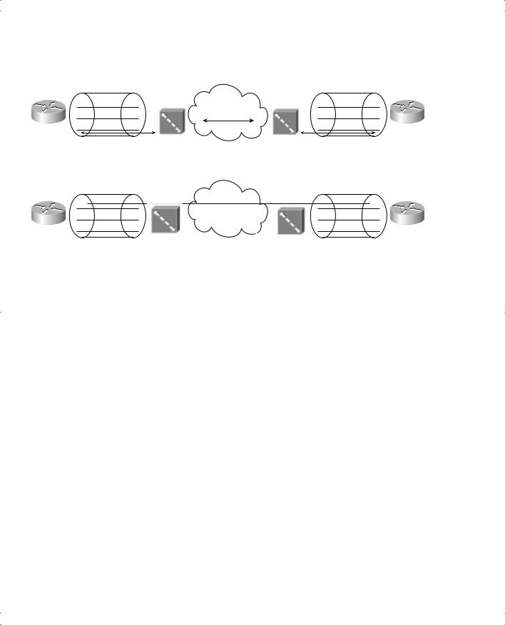
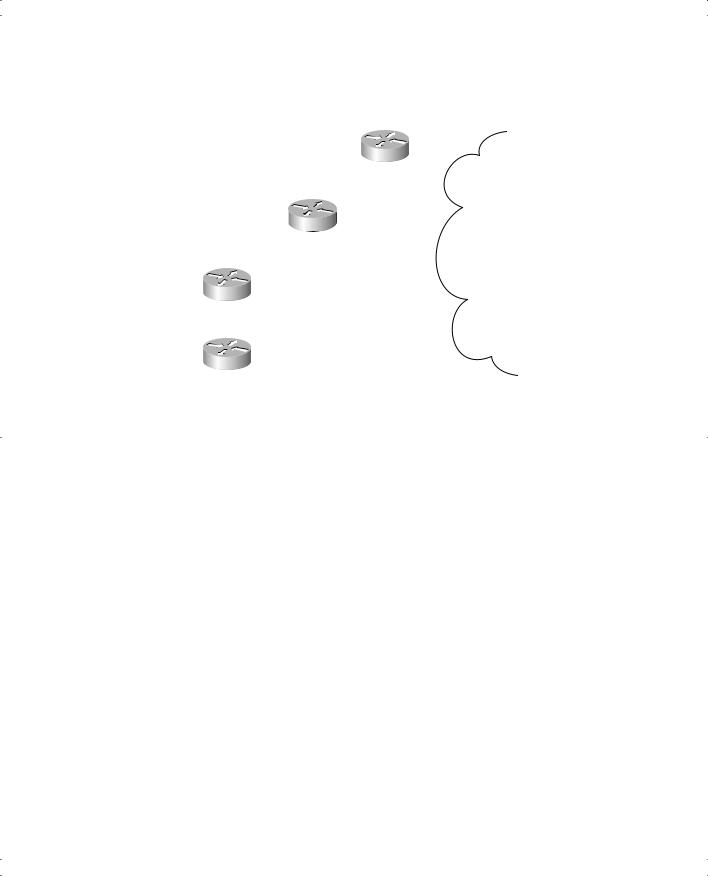
Most people understand concepts better if they can visualize or actually implement a network. A cabling diagram is helpful for examining the reference points and function groups. Figure 10-3 shows the cabling diagram for several examples.
Routers A and B represent typical cabling with a Cisco router, using ISDN, in North America. Router A is ordered with an ISDN BRI U interface; the U implies that it uses the U reference point, referring to the I.430 reference point for the interface between the customer premises and the telco in North America. No other device needs to be installed; the line supplied by the telco is simply plugged into the router’s BRI interface.
Router B uses a BRI card with an S/T interface, implying that it must be cabled to a function group NT1 device in North America. An NT1 function group device must be connected to the telco line through a U reference point in North America. When using a router BRI card with an S/T reference point, the router must be cabled to an external NT1, which in turn is plugged into the line from the telco (the U interface).

332 Chapter 10: ISDN and Dial-on-Demand Routing
Figure 10-3 ISDN Function Groups and Reference Points
|
|
|
|
|
A |
||
|
Uses ISDN Interface |
|
U |
||||
|
|
|
|
||||
|
|
|
|||||
|
|
B |
|
|
|
||
Uses ISDN Interface |
|
|
|
|
U |
||
|
|
|
NT1 |
||||
|
|
|
|
|
|||
|
|
S/T |
Telco |
||||
C |
|
|
|
||||
|
|
||||||
|
|
|
|
||||
|
|
|
|
|
|
||
Uses Serial Interface |
|
|
|
|
|
U |
|
|
TA |
|
NT1 |
||||
|
|
|
|
||||
R |
S/T |
|
|||||
|
|
|
|
|
|
||
|
|
|
|
|
|
||
D |
|
|
|
|
|
|
|
Uses Serial Interface |
|
|
|
|
|
U |
|
|
NT2 |
|
NT1 |
||||
|
|
|
|
||||
S |
T |
|
|||||
|
|
|
|
|
|
||
|
|
|
|
|
|
Both Router A and Router B use an ISDN BRI card, but they have different reference points. The list price of the BRI-U card is typically several hundred dollars higher than a BRI-S/T card, because the BRI-U essentially contains the NT1 function group on the card, making an external NT1 unnecessary.
A router can connect to an ISDN service with a simple serial interface, as shown with Router C in Figure 10-3. Router C must implement an ISDN function group called TE2 (Terminal Equipment 2) and connect directly to a device called a terminal adapter using the R reference point.
Fun, isn’t it? The real goal of ISDN is to allow various migration paths. Imagine that you already own a router at a remote site, and the router does not support ISDN interfaces. You could buy an external ISDN TA and NT1, and use ISDN, for a lot less money than buying a new router with an ISDN BRI-U card. For another site, you might deploy a new router, so you buy a router with a BRI-U card, and you can avoid worrying about all the external devices. In either case, the ITU tried to provide options to the public and to the service providers selling ISDN to the public—with the unfortunate side effect of requiring CCNA candidates to memorize a lot of details!

ISDN Protocols and Design 333
Table 10-5 summarizes the types shown in Figure 10-3. Tables 10-6 and 10-7 summarize the formal definitions.
Table 10-5 Function Groups and Reference Point Summary
|
Function |
Connected to Which |
|
Router |
Group(s) |
Reference Point(s) |
Type of Interface Used in the Router |
|
|
|
|
A |
TE1, NT1 |
U |
ISDN card, U interface |
|
|
|
|
B |
TE1 |
S/T (combined S and T) |
ISDN card, S/T interface |
|
|
|
|
C |
TE2 |
R |
Serial interface (no ISDN hardware/ |
|
|
|
software in the router) |
|
|
|
|
D |
TE1 |
S |
Serial interface (no ISDN hardware/ |
|
|
|
software in the router) |
|
|
|
|
Table 10-6 Definitions for the Function Groups Shown in Figure 10-3
Function |
What the Acronym |
|
Group |
Stands For |
Description |
|
|
|
TE1 |
Terminal Equipment 1 |
ISDN-capable four-wire cable. Understands signaling |
|
|
and 2B+D. Uses an S reference point. |
|
|
|
TE2 |
Terminal Equipment 2 |
Equipment that does not understand ISDN protocols |
|
|
and specifications (no ISDN awareness). Uses an R |
|
|
reference point, typically an RS-232 or V.35 cable, to |
|
|
connect to a TA. |
|
|
|
TA |
Terminal adapter |
Equipment that uses R and S reference points. Can be |
|
|
thought of as the TE1 function group on behalf of a |
|
|
TE2. |
|
|
|
NT1 |
Network Termination |
CPE equipment in North America. Connects with a |
|
Type 1 |
U reference point (two-wire) to the telco. Connects |
|
|
with T or S reference points to other CPE. |
|
|
|
NT2 |
Network Termination |
Equipment that uses a T reference point to the telco |
|
Type 2 |
outside North America or to an NT1 inside North |
|
|
America. Uses an S reference point to connect to |
|
|
other CPE. |
|
|
|
NT1/NT2 |
— |
A combined NT1 and NT2 in the same device. This |
|
|
is relatively common in North America. |
|
|
|