


48 Chapter 2: Spanning Tree Protocol
PortFast
PortFast allows a switch to place a port in forwarding state immediately when the port becomes physically active. However, the only ports on which you can safely enable PortFast are ports on which you know that no bridges, switches, or other STP-speaking devices are connected. So PortFast is most appropriate for connections to end-user devices. If you turn on PortFast for end-user devices, when an end-user PC boots, as soon as the Ethernet card is active, the switch port can forward traffic. Without PortFast, each port must wait MaxAge plus twice Forwarding Delay, which is 50 seconds with the default MaxAge and Forward Delay settings.
Although it isn’t required, you can also figuratively “buy insurance” against someone’s putting a bridge or switch on a PortFast-enabled port. The Cisco BPDU Guard feature, if enabled, tells the switch to disable PortFast ports if a BPDU is received on those ports. This prevents someone from accidentally or maliciously forcing STP convergence in your network.
Rapid Spanning Tree (IEEE 802.1w)
As mentioned earlier in this chapter, the IEEE defines STP in the 802.1d IEEE standard. The IEEE has improved the 802.1d protocol with the definition of Rapid Spanning Tree Protocol (RSTP), as defined in standard 802.1w.
RSTP (802.1w) works just like STP (802.1d) in several ways:
■It elects the root switch using the same parameters and tiebreakers.
■It elects the root port on nonroot switches with the same rules.
■It elects designated ports on each LAN segment with the same rules.
■It places each port in either forwarding or blocking state—although RSTP calls blocking state “discarding” instead of “blocking.”
RSTP can be deployed alongside traditional 802.1d STP bridges and switches, with RSTP features working in switches that support it, and STP features working in the switches that support only STP.
With all these similarities, you might be wondering why the IEEE bothered to create RSTP in the first place. The overriding reason is convergence. STP takes a relatively long time to converge (50 seconds with the default settings). RSTP improves network convergence when topology changes occur.
STP convergence has essentially three time periods, each of which RSTP improves upon. First, a switch must cease to receive root BPDUs for MaxAge seconds before it can begin to transition any interfaces from blocking to forwarding. For any interfaces that need to
Rapid Spanning Tree (IEEE 802.1w) 49
transition from blocking to forwarding, the interface must endure Forward Delay seconds in listening state and Forward Delay more seconds in learning state before being placed in forwarding state. These three waiting periods of (by default) 20, 15, and 15 seconds create STP’s relatively slow convergence.
RSTP convergence times typically take less than 10 seconds. In some cases, they can be as low as 1 to 2 seconds. Before examining how RSTP reduces convergence time, you should know some RSTP terminology and concepts.
RSTP Link and Edge Types
RSTP characterizes the types of physical connectivity in a campus LAN into three different types:
■Link-type point-to-point
■Link-type shared
■Edge-type
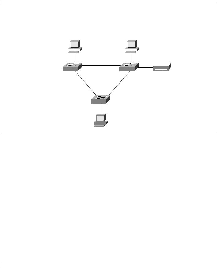
Figure 2-7 shows each type.
Figure 2-7 RSTP Link and Edge Types
Edge-Type
Shared
Hub
Link-Type
Link-Type
Pt-pt
Shared
 Hub
Hub
|
|
|
|
|
|
Edge-Type |
Edge-Type |
|
|
|
|
|
|
|
|
|
|
|
|
|
|
|
|
|
|
|
|||
|
|
|
|
|
|
|
|
|
|
|
|
|||
|
|
|
|
|
|
Pt-Pt |
|
|
|
|
|
|
|
|
|
|
|
|
|
|
|
|
|
|
|
|
|
||
|
|
|
|
|
|
|
|
|
|
|
|
|
|
|
|
|
|
|
|
|
|
|
|
|
|
|
|
|
|
|
|
|
|
|
|
|
|
|
|
|
|
|
|
|
|
|
|
|
|
|
|
|
|
|
|
|
|
|
|
|
|
|
|
|
|
|
|
|
|
|
|
|
|
|
Figure 2-7 shows two sample networks. The network on the left is a typical campus design today, with no hubs. All the switches connect with Ethernet cables, and all the end-user devices also connect with Ethernet cables. The IEEE defined RSTP to improve convergence in these types of networks.

50 Chapter 2: Spanning Tree Protocol
In the network on the right side of the figure, hubs are still in use for connections between the switches, as well as for connections to end-user devices. Most networks do not use hubs anymore. The IEEE did not attempt to make RSTP work in networks that use shared hubs, and RSTP would not improve convergence in the network on the right.
RSTP calls Ethernet connections between switches links and calls Ethernet connections to end-user devices edges. Two types of links exist—point-to-point, as shown on the left side of Figure 2-7, and shared, as shown on the right side. RSTP does not distinguish between point- to-point and shared types for edge connections, although the Cisco ICND course (upon which CCNA is partially based) makes this distinction.
RSTP reduces convergence time for link-type point-to-point and edge-type connections. It does not improve convergence over link-type shared connections. However, most modern networks do not use hubs between switches, so the lack of RSTP support for link-type shared doesn’t really matter.
RSTP Port States
You should also be familiar with RSTP’s new terms to describe a port’s state. Table 2-6 lists the states, with some explanation following the table.
Table 2-6 RSTP and STP Port States
|
|
|
Port Included in Active |
Operational State |
STP State (802.1d) |
RSTP State (802.1w) |
RSTP Topology? |
|
|
|
|
Enabled |
Blocking |
Discarding |
No |
|
|
|
|
Enabled |
Listening |
Discarding |
No |
|
|
|
|
Enabled |
Learning |
Learning |
Yes |
|
|
|
|
Enabled |
Forwarding |
Forwarding |
Yes |
|
|
|
|
Disabled |
Disabled |
Discarding |
No |
|
|
|
|
Similar to STP, RSTP stabilizes with all ports either in forwarding state or discarding state. Discarding means that the port does not forward frames, process received frames, or learn MAC addresses—but it does listen for BPDUs. In short, it acts just like the STP blocking state. RSTP uses an interim learning state, which works just like the STP learning state. However, RSTP needs to use learning state for only a short time.
RSTP Port Roles
RSTP defines a set of port roles. STP also uses port roles, such as root port and designated port. RSTP adds three more port roles, two of which are shown in Figure 2-8. (The disabled state is not shown in the figure.)
Rapid Spanning Tree (IEEE 802.1w) 51
Figure 2-8 RSTP Port Roles
|
Larry |
|
|
Archie |
||||||
|
|
|
|
|
|
|
|
|
|
|
|
|
|
|
|
|
|
|
|
|
|
|
|
|
|
|
|
|
|
|
|
|
|
|
|
|
|
|
|
|
|
|
|
Forwarding
SW1 |
|
|
SW2 |
RSTP |
|
|
|
|
Backup Port |
|
|
Discarding |
|
|
|
Root Port |
|
RSTP |
|
|
|
Alternate |
|
|
|
|
|
|
|
|
|
|
Port |
|
SW3
Bob
Switch SW3 has a root port, just as it would with STP. SW3 also considers its link to SW2 an RSTP alternate port. RSTP designates ports that receive suboptimal BPDUs (BPDUs that are not as “good” as the one received on the root port) as alternate ports. If SW3 stops getting hellos from the root bridge, RSTP on SW3 chooses the best alternate port as the new root port to begin the speedier convergence process.
The other new RSTP port type, backup port, applies only when a single switch has two links to the same segment. To have two links to the same segment, the switch must be attached to a hub, as shown in Figure 2-8. For instance, switch SW2 places one of the two ports
in forwarding state and the other in discarding state. SW2 forwards BPDUs out the port in forwarding state and gets the same BPDU back on the port that is in discarding state. So SW2 knows it has an extra connection to that segment, called a backup port. If the port in forwarding state fails, RSTP on SW2 can immediately place the backup port in forwarding state.