

38 Chapter 2: Spanning Tree Protocol
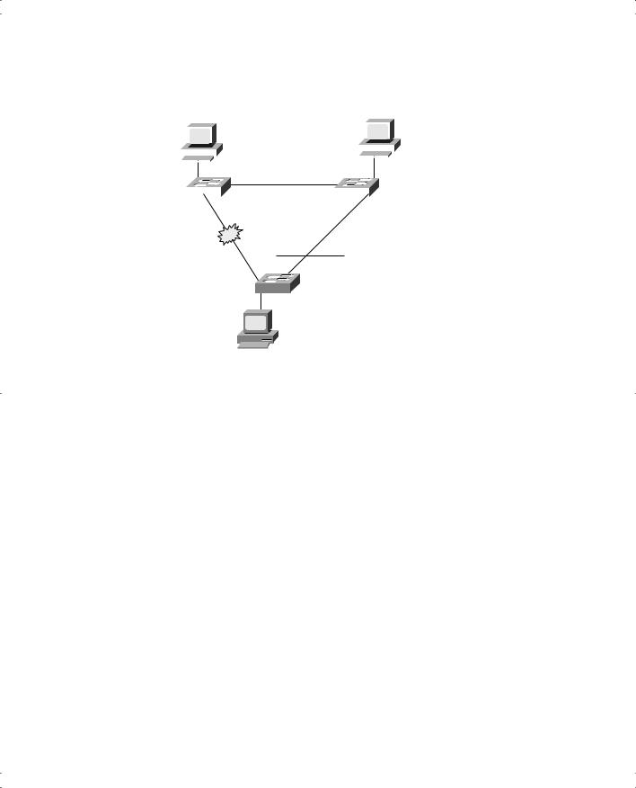
Figure 2-2 Network with Redundant Links and STP After Link Failure
|
Larry |
Archie |
||||||||
|
|
|
|
|
|
|
|
|
|
|
|
|
|
|
|
|
|
|
|
|
|
|
|
|
|
|
|
|
|
|
|
|
|
|
|
|
|
|
|
|
|
|
|
|
|
|
|
|
|
|
|
|
|
|
|
|
|
|
|
|
|
|
|
|
|
0/26 |
0/26 |
|
||
|
|
|
|
|
SW1 |
|
|
SW2 |
|
0/27 |
|
0/27 |
||
Forwarding
0/27
0/26
SW3
Bob
How does STP manage to make switches block or forward on each interface? And how does it converge to change state from blocking to forwarding to take advantage of redundant links in response to network outages? The following sections answer these questions.
How Spanning Tree Works
The STP algorithm creates a spanning tree of interfaces that forward frames. The tree structure creates a single path to and from each Ethernet segment, just like you can trace a single path in a living, growing tree from the base of the tree to each leaf. STP actually places interfaces in forwarding state or blocking state; if an interface has no specific reason to be in forwarding state, STP places the interface in blocking state.
In other words, STP simply picks which interfaces should forward and which shouldn’t.
STP uses three criteria to choose whether to put an interface in forwarding state:
■STP elects a root bridge. STP puts all interfaces on the root bridge in forwarding state.
■Each nonroot bridge considers one of its ports to have the least administrative cost between itself and the root bridge. STP places this least-root-cost interface, called that bridge’s root port, in forwarding state.
Spanning Tree Protocol 39
■Many bridges can attach to the same Ethernet segment. The bridge with the lowest administrative cost from itself to the root bridge, as compared with the other bridges attached to the same segment, is placed in forwarding state. The lowest-cost bridge on each segment is called the designated bridge, and that bridge’s interface, attached to that segment, is called the designated port.
All other interfaces are placed in blocking state. Table 2-2 summarizes the reasons why STP places a port in forwarding or blocking state.
Table 2-2 |
STP: Reasons for Forwarding or Blocking |
|
|
|
|
|
|
|
Characterization of Port |
STP State |
Description |
|
|
|
|
|
All the root bridge’s ports |
Forwarding |
The root bridge is always the designated |
|
|
|
bridge on all connected segments. |
|
|
|
|
|
Each nonroot bridge’s root port |
Forwarding |
The root port is the port receiving the |
|
|
|
lowest-cost BPDU from the root. |
|
|
|
|
|
Each LAN’s designated port |
Forwarding |
The bridge forwarding the lowest-cost |
|
|
|
BPDU onto the segment is the designated |
|
|
|
bridge for that segment. |
|
|
|
|
|
All other ports |
Blocking |
The port is not used for forwarding |
|
|
|
frames, nor are any frames received on |
|
|
|
these interfaces considered for |
|
|
|
forwarding. |
|
|
|
|
Electing the Root and Discovering Root Ports and Designated Ports
STP begins with each bridge claiming to be the root bridge by sending STP messages. STP defines these messages used to exchange information with other bridges, which are called bridge protocol data units (BPDUs). Each bridge begins by sending a BPDU specifying the following:
■The root bridge’s bridge ID—The bridge ID is the concatenation of the bridge’s priority and a MAC address on that bridge (unless it is explicitly configured as another number).
At the beginning of the root-election process, each bridge claims to be root, so each bridge advertises itself as root using its own bridge ID. For instance, Example 2-1 later in this chapter shows output from a switch with a priority of 32768 and a MAC address 0050.f035.a940, combined to form the bridge ID. The lower the priority, the better chance of being root. The IEEE 802.1d STP specification allows for priorities between 0 and 65,535, inclusive.
■The cost to reach the root from this bridge—At the beginning of the process, each bridge claims to be root, so the value is set to 0, which is this bridge’s cost to reach itself. The lower the cost, the better the path, with the range of costs being between 0 and 65,535, inclusive.

40 Chapter 2: Spanning Tree Protocol
■The bridge ID of the sender of this BPDU—This value is always the bridge ID of the sender of the BPDU, regardless of whether the bridge sending the BPDU is the root.
The bridges elect a root bridge based on the bridge IDs in the BPDUs. The root bridge
is the bridge with the lowest numeric value for the bridge ID. Because the two-part bridge ID starts with the priority value, essentially the bridge with the lowest priority becomes the root. For instance, if one bridge has priority 100, and another bridge has priority 200, the bridge with priority 100 wins, regardless of what MAC address was used to create the bridge ID for each bridge/switch.
If a tie occurs based on priority, the root bridge with the lowest MAC address used in the bridge ID is the root. The MAC addresses used to build the bridge IDs should be unique.
Bridges and switches use one of their own burned-in MAC addresses as their bridge ID, so the bridge IDs are unique, because MAC addresses are supposed to be unique. So if the priorities tie, and one switch uses a MAC address of 0020.0000.0000 as part of the bridge ID, and the other uses 0FFF.FFFF.FFF, the first switch (MAC 0200.0000.0000) becomes the root.
The message used to identify the root, its bridge ID, and cost is called a hello BPDU.
STP elects a root bridge, in a manner not unlike a political election. The process of choosing the root begins with all bridges claiming to be the root by sending hello BPDUs with their bridge IDs and priorities. If a bridge hears of a better candidate, it stops advertising itself as root and starts forwarding the hello sent by the better bridge. It works like a political race in which a candidate gives up and leaves the race: The lesser candidate throws his support behind another candidate. Eventually someone wins, and everyone supports the elected switch—which is where the political race analogy falls apart.
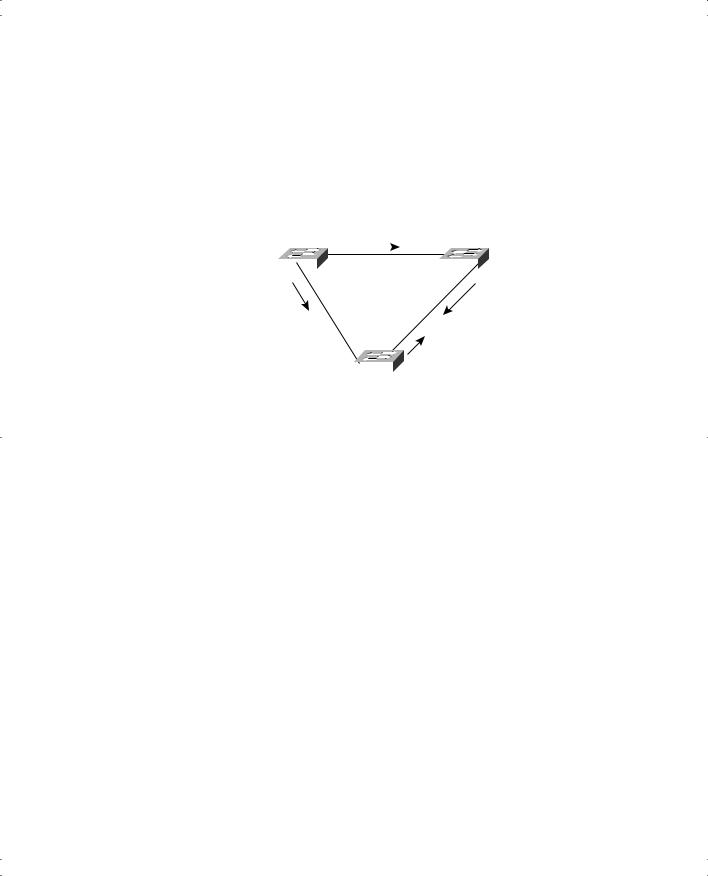
Figure 2-3 outlines part of the process. Imagine that SW1 has advertised itself as root, as have SW2 and SW3. SW2 now believes that SW1 is a better root, but SW1 and SW3 still believe that they each are the best, so they still advertise themselves as root.
Figure 2-3 Root Election Process
Root: SW1
Cost: 0
Root-id 32,768:0200.0000.0001
|
|
|
|
|
|
|
0/26 |
|
|
|
SW1 |
|
|
|
|
|
SW2 |
|
|
|
|
|
|
|
|
|
0/27 |
|
|
Root: SW1 |
|
|
|
|
Root: SW1 |
||||
Cost: 0 |
|
|
|
|
Cost: 100 |
||||
Root-id 32,768:0200.0000.0001 |
|
|
|
|
Root-id 32,768:0200.0000.0001 |
||||
|
|
|
|
0/26 0/27 |
|
|
|
||
Root: SW3 |
|
|
Root: SW3 |
||||||
|
SW3 |
|
|||||||
|
|||||||||
Cost: 0 |
|
|
|
Cost: 0 |
|||||
Root-id 32,768:0200.0000.0003 |
Root-id 32,768:0200.0000.0003 |
||||||||
Spanning Tree Protocol 41
Two candidates still exist in Figure 2-3—SW1 and SW3. So who wins? Well, from the bridge ID, the lower-priority switch wins; if there is a tie, the lower MAC address wins. As shown in the figure, SW1 has a lower bridge ID (32768:0200.0000.0001), so it wins, and SW3 now also believes that SW1 is the better bridge. Figure 2-4 shows the resulting hello messages sent by the switches.
Figure 2-4 SW1 Wins Election
|
|
|
|
SW1 Is Root |
|
|
|
|||
|
|
|
|
Cost = 0 |
|
|
Cost = 100 |
|||
|
|
|
|
|
|
|
|
|||
|
|
|
F |
RP 0/26 |
|
|
||||
|
|
|
|
|||||||
|
SW1 |
|
||||||||
|
|
SW2 |
||||||||
|
F |
|
|
0/27 |
|
|||||
SW1 Is Root |
|
|
|
SW1 Is Root |
||||||
Cost = 0 |
|
|
|
|||||||
|
|
|
Cost = 100 |
|||||||
|
|
|
|
|
|
|
|
|
||
|
|
|
|
RP |
|
|
|
|
|
|
0/26 |
0/27 |
|
|
|
||||||
|
Cost = 150 |
|
|
SW1 Is Root |
||||||
|
|
|
|
|
|
|
|
|||
|
|
|
|
|
SW3 |
|
||||
|
|
|
|
|
|
Cost = 150 |
||||
|
|
|
|
|
|
|
|
|||
SW1’s interfaces are placed in forwarding state because SW1 won the election. All interfaces on the root switch forward. But what about SW2’s and SW3’s interfaces? Well, the second reason that STP places an interface in forwarding state is if it is the root port on that switch. Each switch has one root port, which is the port receiving the least-cost BPDU from the root. In Figure 2-4, SW2’s best cost is seen in the hello entering its port 0/26. Likewise, SW3’s best cost is seen entering its 0/26 port. Therefore, the figure places “RP” beside each of those ports. SW2 and SW3 place those ports in forwarding state.
The final reason that STP places interfaces in forwarding state is if they advertise the lowestcost hello onto a LAN segment—in other words, if the bridge becomes the designated bridge on a segment. In Figure 2-4, both SW2 and SW3 forward hello messages onto the link between them. The cost is calculated by adding the cost in the received hello (0 in this case) to the cost of the interface on which the hello was received. So SW2 adds cost 100 to 0, and
SW3 adds 150 to 0. (The costs of those interfaces are listed in Figure 2-4.) The costs can be configured, or they can default. So, because SW2 advertises the lower-cost hello, SW2’s 0/27 port is the designated port on the LAN segment between SW2 and SW3. SW2 places its port 0/27 in forwarding state because it is the designated port on that segment. (If the costs were the same, the lower bridge ID of the switch sending the BPDUs to the segment would become the designated bridge. In this case, SW2 would win, with bridge ID 32768:0200.0000.0002 versus SW3’s 32768:0200.0000.0003.)