


34 HYPERTHERMIA, INTERSTITIAL
HYPERTENSION. See BLOOD PRESSURE MEASUREMENT.
HYPERTHERMIA, INTERSTITIAL
MICHAEL D. SHERAR
London Health Sciences Centre
and University of Western
Ontario
London, Ontario, Canada
LEE CHIN
University of Toronto
Toronto, Ontario, Canada
J. CARL KUMARADAS
Ryerson University
Toronto, Ontario, Canada
INTRODUCTION
Interstitial hyperthermia or thermal therapy is a minimally invasive method for the treatment of cancer. Radio frequency (RF), microwave, laser light, or ultrasound energy is delivered through one or more thin needle devices inserted directly into the tumor.
Interstitial devices have the significant advantage over external devices of being able to deliver thermal energy directly into the target region, thereby avoiding depositing energy into intervening nontarget tissue. Their main disadvantage is that the needle devices employed often deposit energy over only a small volume. This can make it challenging to deliver an adequate thermal dose to large target regions. This problem was highlighted in an early radiation therapy oncology group (RTOG) phase III trial in which only 1 out of 86 patients was deemed to have received an adequate thermal treatment (1).
These early challenges in interstitial hyperthermia have been addressed, to some extent, through the development of improved heating devices and more detailed monitoring of applicator placement and dose delivery. Quality assurance guidelines have been developed by the RTOG to raise the quality of heating (2). The guidelines recommend pretreatment planning and equipment checks, the implantation of considerations and documentation, the use of thermometry, and the development of safety procedures. Treatment procedures have also been improved through the use of more detailed thermometry, especially using magnetic resonance imaging approaches (3,4).
THERMAL DOSE AND HEAT TRANSFER
The goal of interstitial thermal therapy is to deliver a prescribed dose to a target volume. Thermal dose is defined as equivalent minutes at 43 8C, or TD. The units of TD are minutes, which represents the time tissue would need to be maintained at a constant temperature of 43 8C to have the same effect as the particular time–temperature history that the tissue was exposed to. The thermal dose after & minutes of heating can be calculated if the time–
temperature history is known (5), |
|
||
TDðtÞ ¼ Z0t R43 TðtÞdt |
where |
1 |
|
0:25 for T |
|
43 C |
|
|
|
ð Þ |
|
R ¼ 0:5 for T > 43 C |
ð2Þ |
||
The dose prescribed for treatment depends on whether the heating is being used as an adjuvant to radiation or systemic therapy, or whether it is being used as a stand-alone treatment to coagulate tissue. For the former use, the dose prescribed is typically 10–60 min (Eq. 1) and for the latter it is usually prescribed to be > 240 min (Eq. 2). This is because temperatures employed for adjuvant treatment (usually referred to as hyperthermia) are in the 40– 45 8C range. For stand-alone coagulation (usually referred to as thermal therapy or thermal ablation), temperatures in the range of 55–90 8C are used.
The temperature (T) produced in tissue depends on the heat deposition by the applicator, heat conduction, and blood flow according to
rc @@Tt r ðkrTÞ þ v rT ¼ Q
where r is the tissue mass density, r is the heat capacity of the tissue, k is the thermal conductivity of the tissue, v is the blood velocity profile, and Q is the heat absorbed per unit volume. Detailed knowledge of the blood velocity profile at the capillary level is generally unknown, and even if it were known the calculations would require impractically large computational resources. While several models have been proposed to calculate heat transfer due to perfusion, the Pennes bioheat transfer equation is most often employed (6)
@T
rc @t r ðkrTÞ þ wcbðT TbÞ ¼ Q
where w is blood mass perfusion rate, cb is the blood heat capacity, and Tb is the temperature of the blood entering the treatment field, and v is the velocity field of any convective flow (e.g., as the blood in large vessels). This equation can be used to predict the temperature in tissue, and therefore plan thermal therapy or hyperthermia treatments if the perfusion rate is known. Penne’s equation does not accurately predict for the effect of large blood vessels that must be modeled individually.
ELECTROMAGNETIC HEATING
The heat absorbed (or deposited) in tissue is often described in terms of the power per unit mass. It is called the specific absorption rate or SAR. For electromagnetic devices heat is deposited by the motion of charges or ions. The movement of charge depends on the electric field produced by the applicator in tissue. In microwave and RF hyperthermia, the applicators are driven by sinusoidally time-varying signals. In this case, the electric field can be written in phasor form E such that the electric field is given by, EðtÞ ¼ RðEejvtÞ, where R(x) is the real part of the complex vector x, and v is the angular frequency of the driving
signal. The SAR is then
SAR ¼ Qr ¼ 2sr ðE E Þ
where s is the electrical conductivity of the tissue.
The calculation of the electric field E is based on Maxwell’s equations. For microwave devices, these equations are combined to produce the Helmholtz vector wave equation
r r E k2E ¼ 0
where k is the complex-valued wavenumber given by k2 ¼ v2me jvms and m is the magnetic permeability of the medium, which for tissue is the same as the free-space value, and e is the electrical permittivity of the medium. The divergence free condition, r E ¼ 0, may have to also be explicitly imposed if the solution technique does not inherently do this.
For RF devices, the frequency is sufficiently low that the displacement currents can be ignored. In this case, it is usually simpler to determine the scalar electric potential V and from this derive the electric field, E ¼ rV. The electric potential obeys a Poisson-type equation
r ðkrVÞ ¼ 0
For models of both microwave and RF devices, the governing Helmholtz or Poisson equation is imposed in a domain with a known electric field or electric potential specified as a boundary condition to represent the power source. Another condition that is often imposed on the surface of metals is that the tangential component of the electric field is zero, nˆ E ¼ 0.
The solution of the governing equations with appropriate boundary conditions is impossible for all but the simplest geometries. For most practical cases, numerical methods and computational tools are required. The finite difference time domain (FDTD) method (7), the finite element (FE) method (8,9), and the volume surface integral equation (VSIE) method (10) are the most commonly utilized methods for solving the governing equations in electromagnetic hyperthermia and thermal therapy. In the FDTD method, the domain is discretized into rectangular elements. The accuracy of a FDTD solution depends on the size of the mesh spacing. Smaller elements produce more accurate solutions, but also require more memory to store the system of equations. Since the grids are rectangular, their nonconformation to curved tissue boundaries produces a stair-casing effect. Therefore, a large number of elements are required to model such geometries accurately. Unlike the FDTD method, the FE method uses tetrahedral meshes in the domain and the VSIE method uses triangular meshes on domain surfaces. Tetrahedral and triangular meshes are more suitable than regular finite difference grids for three-dimensional (3D) modeling since they do not have the stair casing effect at tissue boundaries.
RADIO FREQUENCY DEVICES
In RF, thermal therapy tissue is heated by electrical resistive (or J) heating. The heating devices, or applicators, are
HYPERTHERMIA, INTERSTITIAL |
35 |
Figure 1. The heating in RF devices is caused by current flow. Since the current flows from the heating electrode to the ground pad, there is a high current density near the electrode due to its small size compared to the ground pad. This results in heating that is localized to the heating electrode.
inserted interstitially to produce currents in the tissue. The currents typically oscillate sinusoidally in the kilohertz or low megahertz frequency range. As a result, this modality is often referred to as radio frequency or RF heating. There devices have an advantage over other interstitial devices in their simplicity and low cost. They can operate at low frequency, and therefore do not require complex power generators. The RF probes, due their simplicity, tend to have the smallest diameter of all the types of interstitial heating probes. The RF heating technique has been extensively reviewed by others (11–15).
There are several designs of RF interstitial devices, which may be categorized into three groups. The simplest design consists of a single electrode at a probe tip (often referred to as a needle electrode) (9,16–20). The current flows between a single electrode at the end of an applicator and a large ground plate placed at a distal site. Since the current flows between a small electrode and a large plate, the currents are concentrated near the electrodes resulting in SAR patterns that are localized to the electrodes as illustrated in Fig. 1.
With these single electrode probes the coagulation diameter is usually limited to 1.6 cm. Therefore several probes are needed to cover a larger area (21), or a single probe can be inserted into several locations, sequentially, during a treatment.
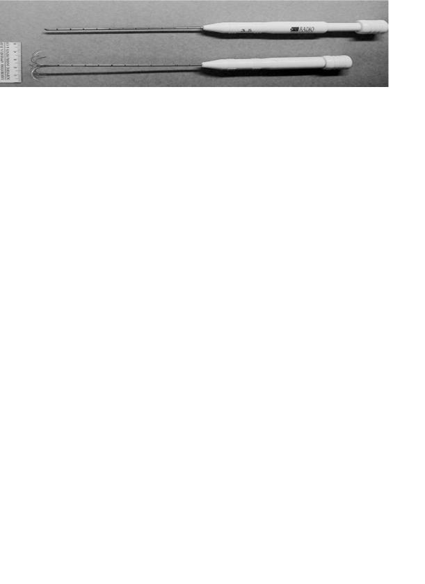
Since it is desirable to avoid the insertion of multiple interstitial probes, single probes that release multiple electrodes outward from the probe tip have been designed to produce large coagulation volumes. Two examples of these are the Boston Scientific (Watertown, MA; formerly Radio Therapeutics Corporation, Mountain View, CA) RF 3000 system in which 10–12 tines are deployed from a cannula to form an umbrella shape (Fig. 2) and the RITA Medical Systems (Mountain View, CA) Starburst probes with up to 9 tines. In some configurations, some of the tines in the Starburst probes are replaced with dedicated thermocouples while others are hollow electrodes through which saline can be infused into the target region to enhance heating. These multielectrode probes are able to produce coagulation regions with diameters up to 7 cm, although complete coverage of a large region can be difficult in high blood flow organs, such as the kidney (22).
The negative RTOG phase III trial, in which only 1 out of 86 patients was deemed to have received an adequate thermal dose (1) illustrated the need to not only increase the target volume coverage, but also to control the heating.
36 HYPERTHERMIA, INTERSTITIAL
Figure 2. A Boston Scientific (Watertown, MA; formerly Radio Therapeutics Corporation, Mountain View, CA) insterstital RF probe with 10 tines that are deployed from the cannulus after insertion into a target region. The deployed tines produce a coagulation zone that is larger than the zone that can be produced by a single electrode probe. The top probe is shown with the tines undeployed (ready for insertion) and the bottom probe shows the probe with the tines deployed (as they would be after insertion).
Control is needed to enable the conformation of the heating to irregularly shaped target volumes while avoiding nearby organs at risk and to compensate for heterogeneous cooling by the vasculature (23). Partial control can be achieved by appropriate positioning of the probes and the adjustment their power. Further control along the direction of the probe is also needed (24,25) and multielectrode current source (MECS) applicators have been developed to provide this capability (26). The MECS applicators contain several electrodes placed along their length with the amplitude and phase of each electrode independently controlled. In the most common configuration, the electrodes are capacitively coupled (insulated) with the tissue. The electric fields induced by the electrodes produce currents in the tissue that cause heating. Since the electrodes are capacitively coupled, the probes can be inserted into brachytherapy catheters, for example, making it feasible to add interstitial heating as a simultaneous adjuvant to brachytherapy (interstitial radiation therapy). The electric field (and hence current) may be induced between electrodes on the same probe or on separate probes, or it may be induced between the probe electrodes and a grounding plane.
MICROWAVE DEVICES
Microwave applicators can produce larger coagulation regions than RF applicators due to their radiative nature. However, the construction of the power generator and matching circuitry makes these devices more complex, and therefore more expensive. Due to this, microwave interstitial hyperthermia has been used less often in the clinic than RF interstitial hyperthermia.
Ryan et al. reviewed and compared several types of microwave interstitial applicators (27) and several excellent reviews of microwave interstitial thermal therapy exist (28–32). The two most commonly used devices are the dipole antenna and the helical antenna. The dipole antenna is the simplest form of microwave interstitial antenna (7,8,33). It is usually constructed from a coaxial cable with the outer conductor removed from an end section (typically 1 or 2 cm in length) to expose the inner conductor (Fig. 3). A power generator feeds a sinusoidally oscillating signal into the cable at one of the ISM frequency bands between 400 MHz and 3 GHz. The innerand
outer-conductor electrodes at the tip of the coaxial cable act as an antenna that produces microwaves that radiate out into the tissue. Tissue is an attenuating medium that absorbs microwaves, and this absorbed energy is converted into heat in the tissue.
The radiative or active length of a typical dipole interstitial device is 1–3 cm. The devices produce a coagulation region that is ellipsoidal shaped with a large axis of up to 3 cm along the length of the antenna and a small axis of up to 2 cm diameter. The drawback of the dipole applicator is that the region of highest SAR, or hot spot, is located at the point at which the outer conductor is cut away. Therefore, the tips of these antennas have to be inserted past the center of the target region, and this can be a problem if the target region is located adjacent to a critical structure.
A further problem with dipole antennas is that the SAR patterns are sensitive to the depth to which the antenna is inserted into tissue (8). A second common microwave applicator design, referred to as a helical antenna (34– 36), has been designed to make the applicator insensitive to its insertion depth. In this applicator, one electrode is wrapped in a helix pattern around an exposed coaxial cable (Fig. 4). The antennas are also designed to extend the heating pattern along the applicator and toward the tip of the antenna compared to the dipole antenna. The SAR pattern from a BSD Medical (Salt Lake City, UT) helical antenna is shown in (Fig. 5). The antenna was operating at 915 MHz. The measurement was performed using the thermographic imaging technique (37) and demonstrates
Figure 3. A schematic representation of a microwave interstitial dipole antenna applicator. The outer conductor of a coaxial cable is stripped away to produce a radiating section.
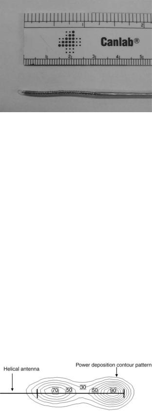
Figure 4. Shown here is a BSD Medical (Salt Lake City, UT) helical microwave applicator. The inner conductor of a coaxial cable is extended backward in a helical pattern around the dielectric insulator. There is no connection between the helical section and the outer conductor.
that the heating extends along the length of the helix and that the hot spot is close to the tip of the applicator.
Interstitial microwave applicators have the advantage over RF applicators in the ability to use arrays of applicators to dynamically steer the SAR pattern (33). For large target volumes, several applicators can be inserted. The heating pattern can then be adjusted by not only adjusting the power to each applicator, but also by adjusting the relative phase of the signal to each applicator. The phase can be adjusted such that the microwaves produced by the applicators interfere constructively in regions that require heating and interfere destructively in regions that should be spared. The predetermination of the phase required for each applicator can be calculated during treatment planning. This is a challenging calculation for applications in which tissue is electrically heterogeneous or the placement of the applicators cannot be accurately predicted. In these cases real-time monitoring of the treatment is required and a manual or computer run feedback control is used to set the phase of the applicators to produce the desired heating profile.
The size of the coagulation volume is limited by the maximum temperature in the treatment field. Since the maximum temperature is usually located at the applicator, it is possible to increase the coagulation volume by cooling adjacent to the applicator. Using this technique, the cross-
Figure 5. The normalized SAR pattern along the coronal plane of a BSD Medical (Salt Lake City, UT) helical applicator operating at 915 MHz. The image was provided courtesy of Claire McCann.
HYPERTHERMIA, INTERSTITIAL |
37 |
section area of a coagulation volume has been noted to increase by a factor of 2.5 in one study (38) and the coagulation volume diameter was found to increase from 1.2 to 2.4 cm (39). In microwave heating, the cooling is usually done by passing water or air through the catheter containing the antenna (29,38,40). In RF heating, cooling water is passed inside the electrode to cool the tissue near the electrode (41,42).
In RF heating, it is also possible to increase the coagulation volume by saline injection from the lumen of the electrode (43). Since saline is electrically conductive, injecting it into the tumor increases the electrical conductivity of the tumor, and hence the SAR in the tumor. This technique has not gained popularity due to the inability of control the flow of saline in the tumor, resulting in irregular and unpredictable coagulation regions being produced.
CLINICAL STUDIES WITH MICROWAVE AND RF DEVICES
Interstitial microwave and RF heating systems have been widely used to clinically treat a variety of tumors in phase I (34,44–47), phase II (18,32,44–49) and phase III trials (1,50). The RF systems have been used to treat a large range of sites, including brain (45), head and neck (1), breast (1), myocardium (51), lung (14), liver (11,52), pancreas (18), prostate (48), and kidney (44,53). Microwave systems have also been used to treat a large range of sites, including liver (4), prostate (both carcinoma and benign hyperplasia) (29,36), head and neck (1,32,49), brain (34,50), breast (1), and other pelvic areas (1). The heat treatments are used alone (29,36), or combined with external beam radiation (54), interstitial radiotherapy (brachytherapy) (1,32,46), and/or chemotherapy (17). The heat treatments are used alone (29,36), or combined with external beam radiation (29,36,48,54,55), combined with external beam radiation (54) or interstitial radiotherapy (brachytherapy) (1,32,46,48,55), and with chemotherapy (17).
The interstitial hyperthermia treatments are usually administered under ultrasound, CT or MR guidance. During the treatment the hyperechoginicity of microbubbles that can be produced at sufficiently high temperatures can provide some real-time ultrasound feedback of the treatment. Posttreatment evaluation can be performed using contrast enhanced ultrasound, CT or MR. The vasculature in the coagulated volume is destroyed and the destroyed volume can be identified as an unenhanced region in the image (41,56,57).
LASER DEVICES
First described in 1983 by Bown (58), Interstitial Laser Photocoagulation (ILP) [sometimes referred to as Laser Induced Thermal Therapy (LITT)] involves the use visible or near infra-red (IR) light delivered through fibre optic cables to heat tissue for therapeutic purposes. The ILP has been investigated as an experimental treatment for a variety of solid tumors including liver, breast, stomach, pancreas, kidney, lung, and bone (59). The tissue temperature is raised causing coagulation of the target volume. Similar to the microwave and RF cases, the production of

38 HYPERTHERMIA, INTERSTITIAL
heat in a local volume of tissue results from the amount of absorbed laser energy, S(r). In biomedical treatments, such as LITT, it is the total absorbed laser energy that typically determines the therapeutic outcome. It is equal to the product of the local fluence rate, f(r) which is the total photon power over all directions that pass through a point area of space, and the absorbing characteristics, ma(r) of the tissue (60):
SðrÞ ¼ maðrÞfðrÞ
The absorbed optical energy deposition pattern is governed by the absorption and scattering characteristics of the tissue. An absorption event causes the interacting molecule to enter a vibrational–rotational state that results in a transfer of energy to surrounding molecules that manifests as a local increase in temperature (61). Absorption occurs due to interactions with native molecules called chromophores with examples including melanin, hemoglobin, and water. In a given tissue, the concentration weighted sum of the absorption of different chromophores leads to its bulk macroscopic absorption. Scattering refers to a directional change in light propagation and likely results from differences in the index of refraction in the various cellular components, such as the between cell membranes and the extracellular space. Here the scattering is assumed to be elastic with no change in energy occurring during the interaction. The statistical quantities that govern light interactions are the scattering coefficient, ma(cm 1) and absorption coefficient, ma(cm 1) and are defined, respectively, as the probability of scattering or absorption per average distance traveled (also known as the mean free path). In the case of scattering, consideration is given to the probability of scatter in a particular direction. An additional parameter known as the anisotropy factor, g, quantifies this directionality by integrating the average cosine of the scattering probability over all directions. When g ¼ 0, scattering is isotropic. However, in the case of biological tissues g typically lies within the range of 0.7 and 0.99 meaning that scattering typically occurs in the forward direction. The reduced scattering coefficient, m0s ¼ msð1 gÞ, allows light scattering to be approximated as isotropic although scattering events are actually in the forward direction. The inverse of the reduced scattering coefficient is, therefore, the average distance that light travels before it changes direction from its original direction of propagation (62).
In theory, Maxwell’s equations could be used to calculate the scattering and absorption of the EM vector fields due to the underlying tissue components (63). In this case, the tissue microstructure could be modeled as random perturbations, e1(r) in the dielectric constant around a mean value, e0(r), with the total dielectric constant, e(r), given by the sum of these quantities. However, in practice, due to the complex and random composition of tissue, a complete and accurate description of e(r) has yet to be realized. Instead a more commonly used solution is to consider light as a stream of neutral particles or photons with individual quanta of energy that propagate elastically throughout the medium. This formalism is governed by radiative transport theory (64), and assumes light to be
monochromatic while ignoring its conventional wave characteristics, such as polarization, diffraction, interference, and fluorescence. Although incomplete, the photon model has been shown to be consistent with experimental measurements in turbid media (65).
A commonly employed model of photon propagation is the Monte Carlo (MC) method (66), which utilizes probability distributions to simulate the propagation of thousands to millions of individual photon packets based on the optical properties of tissue to arrive at a statistical representation of the overall light distribution. The MC is amenable to heterogeneous and arbitrary geometries and does not suffer from the limiting assumptions of analytical solutions. However, its primary disadvantage is the requirement of long computational times, on the order of hours to days, to achieve reasonable statistics. Regardless, with the increasing speed of modern computers, the Monte Carlo method remains a viable option for photon simulations. The reader is referred to an excellent review by Roggan and Muller (67) for the implementation of the MC model for treatment planning of LITT.
Alternatively, one may employ formal solutions to the governing equations for photon transport. The energy flow of photons in a scattering and absorbing medium is described by the radiative transfer equation (RTE) (64). The RTE is an integro differential equation that describes the energy conservation of photons within an infinitesimally small volume that result from losses due to absorption and scattering as well as gains arising from photons scattered from other directions and from the laser source. Analytical solutions to the RTE are difficult to obtain. Hence, various approximations have been proposed to convert the RTE to a more mathematically tractable and practical form. A standard technique, called the Pn approximation, expands the radiance and source as a finite series of spherical harmonics to nth order. The P1 approximation is the simplest of these expansions and in the steady state is also known as the diffusion approximation (63,64):
2 * ma * * 1 *
r fð r Þ D ð r Þfð r Þ ¼ D Sð r Þ
*
Here fð r Þ is the photon fluence rate, while D is the photon diffusion coefficient given by
1
D ¼ 3½m0s þ ma&
The primary assumption of the diffusion equation, that is linear flux anisotropy, is only accurate when the scattering properties of the medium are much larger than the absorption properties and at locations > 1/m0s from the source. A number of analytical solutions to the diffusion equation exist for simple but practical geometries. The solution for a point source in an infinite homogeneous medium is given by (63)
* |
|
Poeð meff rÞ |
fð r |
Þ ¼ |
|
4pr |
This solution is particularly useful as, assuming an infinite medium, it may be integrated numerically to provide the light distribution of cylindrical or extended source

of arbitrary geometries. However, it is well known that tissue optical properties often change from their native state after undergoing thermal coagulation. This results in heterogeneities in optical properties that effect the overall light distribution (68). In such cases, analytical solutions are available only for the simplest geometries and numerical methods such as the finite element (69), finite difference (70), and boundary element method (71) must be employed. A thorough discussion of these methods was given in the preceding section for microwaves and their implementation in the case of photon propagation is the same.
Initially, bare tipped optical fibers were used to deliver laser light to the tumor. High temperatures immediately adjacent to the fiber tip cause the tissue to char and form a zone of carbonization. The charred fiber then acts as a point heat source and the temperature of the fiber increases significantly leading to vacuolization of the surrounding tissue. The volume of coagulation around the fiber grows until thermal equilibrium is reached at the edges of the lesion. Here, the conduction of heat from the fiber is balanced by the tissue’s ability to remove energy through blood flow and thermal conduction.
The size of the lesion depends on the thermal conduction properties of the tissue, but would normally be limited to2 cm in diameter. Larger tumors require multiple optical fiber implants to enable complete coverage of the tumor volume. For example, a 4 cm diameter tumor would require at least eight fibers to fully coagulate the tumor.
The limitations of the bare tipped fibers have been addressed in two ways. The first was to employ a line source geometry instead of a point source. This can be achieved by using a diffusing tip fiber where light gradually leaks out of the fiber over an extended distance of a few centimeters. The second approach is to restrict the temperature of the fiber to lower than the charring threshold by controlling the power delivered to the fiber. If charring is avoided, light can propagate into the tissue resulting in heating at a distance from the fiber and a broader SAR pattern. These two approaches can be combined to achieve greater lesion volumes from single fibers. Heisterkamp et al. (72) demonstrated an almost doubling of the coagulated volume from 4.32 cm3 (bare tipped) to 8.16 cm3 (temperature restricted diffusing tip) using such an approach.
The other major factor that affects the lesion size is the wavelength of the light used. Somewhat counterintuitively, light that is less absorbed by tissue, results in greater lesion sizes. This is because the light can penetrate further into the tissue, and therefore directly heat at greater distances from the fiber. The availability of high power sources at two specific wavelengths (810 nm as produced by diode lasers and 1064 nm as produced by Nd:YAG lasers) has dominated the development of interstitial laser thermal therapy. Wyman et al. (73) have shown that 1064 nm light can enable the creation of greater lesion sizes due to its greater penetration. However, Nd:YAG lasers are large, generally immobile and inconvenient and so many have adopted 810 nm as the wavelength of choice due to the availability of compact and inexpensive sources. More recently 980 nm lasers have been employed to combine mobility with greater light penetration (74,75).
HYPERTHERMIA, INTERSTITIAL |
39 |
Differences between Nd:YAG and Diode lasers are only realized if charring is avoided. Once charring and carbonization has occurred the fiber acts as a point or line heat source. There is no further light propagation into the tissue and subsequent heating has no wavelength dependency. In order to exploit the penetration of light into the tissue, the fiber tip temperature must be controlled to avoid charring. Achieving such control is somewhat challenging asthetemperatureofthe tipcanriseveryquicklyina positive feedback loop. As charring begins, the rate of temperature rise increases that causes an increasing rate of charring. Robust, automatic feedback control mechanisms are necessary to ensure controlled heating and lesion formation.
INTERSTITIAL ULTRASOUND
The possibility of developing interstitial ultrasound devices for hyperthermia applications was proposed by Hynynen in 1992 (76). The initial studies examined various design parameters including the choice of ultrasound frequency, electric and acoustic power, and catheter cooling. As Hynynen showed (76), thin interstitial ultrasound applicators were likely capable of heating perfused tissue to therapeutic temperatures.
Ultrasound is a high frequency longitudinal pressure wave that can pass relatively easily through soft tissue. Consequently, it has been useful as an energy source for diagnostic imaging where focussed ultrasound radiators are used to produce high resolution images of soft tissue abnormalities. During transmission through tissue energy is lost due to absorption and to a much lesser extent to scattering. The absorption is caused by friction as the pressure wave causes relative motion of the tissue components. These frictional forces cause heating that can be significant if the incident ultrasound power is high enough. The absorption, a is frequency dependent where
a ¼ a f m
and a and m are coefficients that are variable between tissues although m is 1.5 for most soft tissues. Rapidly increasing absorption with frequency is the main reason that the penetration of diagnostic imaging is limited at very high ultrasound frequencies. Higher penetration is also the reason that relatively low ultrasound frequencies are used for ultrasound heating. Typically, frequencies in the range 0.5–2 MHz have been used in external focused ultrasound heating applications. However, this becomes problematic for interstitial devices that are small and resonate at high ultrasound frequencies.
Interstitial ultrasound applicators have since been developed and are usually designed as thin tubular radiators. The radiator consists of a piezoelectric material that will resonate acoustically at a frequency f determined by the wall diameter d:
f ¼ 2vd
where v is the speed of sound in the piezoelectric material (e. g., 4000 m s 1 in the piezoelectric material PZT 4A). For interstitial applicators, thin radiators are required. A wall

40 HYPERTHERMIA, INTERSTITIAL
thickness of 0.2 mm, for example, would translate into an operating frequency of 10 MHz (76). The SAR for a cylindrical applicator is dependent on its dimensions and the frequency of operation as given by
SAR ¼ 2a fI0 r e 2m f ðr r0Þ r0
where a is the ultrasound absorption coefficient in tissue, I0 is the intensity of ultrasound at the applicator surface, r0 is the radius of the applicator, r is the distance from the centre of the applicator to the point of interest and m is the attenuation coefficient of ultrasound that includes absorption and scattering. Skinner et al. (77) have calculated and compared the SAR of ultrasound, laser, and microwave applicators assuming a simple cyclindrical radiation pattern for each. The SAR of all these applicators is dominated by the thin cylindrical geometry so that despite the larger penetration depth of ultrasound, only slightly larger diameter lesions can be produced. In order to overcome the limiting geometry, new interstitial ultrasound applicators have been developed that take advantage of the focusing ability of ultrasound (78) or that employs acoustic matching that can result in efficient transmission at multiple frequencies (79).
The development of interstitial ultrasound applicators is still at the preclinical stage (80,81) although larger, intracavitary applicators are being applied in the treatment of prostate cancer using a transrectal technique (82).
BIBLIOGRAPHY
1.Emami BC, et al. Phase III study of interstitial thermoradiotherapy compared with interstitial radiotherapy alone in the treatment of recurrent or persistent human tumors: A prospectively controlled randomized study by the Radiation Therapy Oncology Group. Inte J Rad Oncol Biol Phy 1996;34(5): 1097–1104.
2.Emami BP, et al. RTOG Quality Assurance Guidelines for Interstitial Hyperthermia. Inter J Rad Oncol Biol Phy 1991; 20(5):1117–1124.
3.Peters RD, et al. Magnetic resonance thermometry for predicting thermal damage: An application of interstitial laser coagulation in an in vivo canine prostate model. Magn Reson Med 2000;44(6):873–883.
4.Morikawa S, et al. MR-guided microwave thermocoagulation therapy of liver tumors: Initial clinical experiences using a 0.5 T open MR system. J Magn Reson Imaging 2002;16(5):576– 583.
5.Sapareto SA, Dewey WC. Thermal dose determination in cancer therapy. Int J Radiat Oncol Biol Phys 1984;10(6): 787–800.
6.Pennes HH .Analysis of tissue and arterial blood temperatures in the resting human forearm. 1948. J Appl Physiol 1998; 85(1):5–34.
7.Camart JC, et al. New 434 MHz interstitial hyperthermia system monitored by microwave radiometry: theoretical and experimental results. Intern J Hypertherm 2000;16(2):95– 111.
8.Mechling JA, Strohbehn JW. 3-Dimensional Theoretical SAR and Temperature Distributions Created in Brain-Tissue by 915 and 2450 MHz Dipole Antenna-Arrays with Varying Insertion Depths. Intern J Hypertherm 1992;8(4):529–542.
9.Uzuka T, et al. Planning of hyperthermic treatment for malignant glioma using computer simulation. Int J Hypertherm 2001;17(2):114–122.
10.Wust P, et al. Simulation studies promote technological development of radiofrequency phased array hyperthermia. Int J Hypertherm 1996;12(4):477–494.
11.Haemmerich D, Lee Jr FT. Multiple applicator approaches for radiofrequency and microwave ablation. Int J Hypertherm 2005;21(2):93–106.
12.McGahan JP, Dodd GD, 3rd. Radiofrequency ablation of the liver: current status. AJR Am J Roentgenol 2001;176(1):3–16.
13.Friedman MI, et al. Radiofrequency ablation of cancer. Cardiovasc Intervent Radiol 2004;27(5):427–434.
14.Lencioni RL, et al. Radiofrequency ablation of lung malignancies: where do we stand? Cardiovasc Intervent Radiol 2004;27(6): 581–590.
15.Gazelle GS, Goldberg SN, Solbiati L, Livraghi T. Tumor ablation with radio-frequency energy. Radiology 2000;217(3): 633–646.
16.Goletti O, et al. Laparoscopic radiofrequency thermal ablation of hepatocarcinoma: preliminary experience. Surg Laparosc Endosc Percutan Tech 2000;10(5):284–290.
17.Morita K, et al. Combination therapy of rat brain tumours using localized interstitial hyperthermia and intra-arterial chemotherapy. Inter J Hypertherm 2003;19(2):204–212.
18.Matsui Y, et al. Selective thermocoagulation of unresectable pancreatic cancers by using radiofrequency capacitive heating. Pancreas 2000;20(1):14–20.
19.Aoki H, et al. Therapeutic efficacy of targeting chemotherapy using local hyperthermia and thermosensitive liposome: evaluation of drug distribution in a rat glioma model. Int J Hypertherm 2004;20(6):595–605.
20.Lencioni R, et al. Radio-frequency thermal ablation of liver metastases with a cooled-tip electrode needle: results of a pilot clinical trial. Eur Radiol 1998;8(7):1205–1211.
21.Haemmerich D, et al. Large-volume radiofrequency ablation of ex vivo bovine liver with multiple cooled cluster electrodes. Radiology 2005;234(2):563–568.
22.Rendon RA, et al. The uncertainty of radio frequency treatment of renal cell carcinoma: Findings at immediate and delayed nephrectomy. J Urol 2002;167(4):1587–1592.
23.Crezee J, Lagendijk JJ. Temperature uniformity during hyperthermia: the impact of large vessels. Phys Med Biol 1992;37(6):1321–1337.
24.vanderKoijk JF, et al. Dose uniformity in MECS interstitial hyperthermia: The impact of longitudinal control in model anatomies. Phys Med Biol 1996;41(3):429–444.
25.VanderKoijk JF, et al. The influence of vasculature on temperature distributions in MECS interstitial hyperthermia: Importance of longitudinal control. Intern J Hypertherm 1997; 13(4):365–385.
26.Kaatee RSJP. Development and evaluation of a 27 MHz multielectrode current-source interstitial hyperthermia system. Med Phys 2000;27(12):2829–2829.
27.Ryan TP. Comparison of 6 Microwave Antennas for Hyperthermia Treatment of Cancer—SAR Results for Single Antennas and Arrays. Intern J Rad Oncol Biol Phys 1991; 21(2):403–413.
28.Roemer RB. Engineering aspects of hyperthermia therapy. Annu Rev Biomed Eng 1999;1:347–376.
29.Sherar MD, Trachtenberg J, Davidson SRH, Gertner MR. Interstitial microwave thermal therapy and its application to the treatment of recurrent prostate cancer. Intern J Hypertherm 2004;20(7):757–768.
30.Fabre JJ, et al. 915 MHz Microwave Interstitial Hyperthermia. 1. Theoretical and Experimental Aspects with Temperature Control by Multifrequency Radiometry. Intern J Hypertherm 1993;9(3):433–444.
31.Camart JC, et al. 915 MHz Microwave Interstitial Hyperthermia. 2. Array of Phase-Monitored Antennas. Intern J Hypertherm 1993;9(3):445–454.
32.Prevost B, et al. 915 MHz Microwave Interstitial Hyperthermia. 3. Phase-II Clinical-Results. Intern J Hypertherm 1993; 9(3):455–462.
33.Camart JC, et al. Coaxial Antenna-Array for 915 MHz Interstitial Hyperthermia—Design and Modelization Power Deposition and Heating Pattern Phased-Array. IEEE Trans Microwave Theory Tech 1992;40(12):2243–2250.
34.Fike JR, Gobbel GT, Satoh T, Stauffer PR. Normal Brain Response after Interstitial Microwave Hyperthermia. Intern J Hypertherm 1991;7(5): 795–808.
35.McCann C, et al. Feasibility of salvage interstitial microwave thermal therapy for prostate carcinoma following failed brachytherapy: studies in a tissue equivalent phantom. Phys Med Biol 2003;48(8):1041–1052.
36.Sherar MD, et al. Interstitial microwave thermal therapy for prostate cancer. J Endourol 2003;17(8):617–625.
37.Guy A. Analysis of Electromagnetic Fields Induced in Biological Tissues by Thermographic Studies on Equivalent Phanton Models. IEEE Trans Biomed Eng 1971;19:205– 214.
38.Trembly BS, Douple EB, Hoopes PJ. The Effect of Air Cooling on the Radial Temperature Distribution of a Single Microwave Hyperthermia Antenna In vivo. Intern J Hypertherm 1991;7(2):343–354.
39.Goldberg SN, et al. Radiofrequency tissue ablation: increased lesion diameter with a perfusion electrode. Acad Radiol 1996;3(8):636–644.
40.Eppert V, Trembly BS, Richter HJ. Air Cooling for an Interstitial Microwave Hyperthermia Antenna—Theory and Experiment. IEEE Trans Biomed Eng 1991;38(5):450–460.
41.Goldberg SN, et al. Treatment of intrahepatic malignancy with radiofrequency ablation: Radiologic-pathologic correlation. Cancer 2000;88(11):2452–2463.
42.Solbiati L, et al. Hepatic metastases: percutaneous radiofrequency ablation with cooled-tip electrodes. Radiology 1997; 205(2):367–373.
43.Livraghi T, et al. Saline-enhanced radio-frequency tissue ablation in the treatment of liver metastases. Radiology 1997;202(1):205–210.
44.Michaels MJ, et al. Incomplete renal tumor destruction using radio frequency interstitial ablation. J Urol 2002;168(6):2406– 2409.
45.Takahashi H, et al. Radiofrequency interstitial hyperthermia of malignant brain tumors: Development of heating system. Exper Oncol 2000;22(4):186–190.
46.Seegenschmiedt MH, et al. Clinical-Experience with Interstitial Thermoradiotherapy for Localized Implantable Pelvic Tumors. Am J Clin Oncol Cancer Clin Trials 1993;16(3): 210–222.
47.Seegenschmiedt MH, et al. Multivariate-Analysis of Prognostic Parameters Using Interstitial Thermoradiotherapy (Iht-Irt)—Tumor and Treatment Variables Predict Outcome. Intern J Rad Oncol Biol Phys 1994;29(5):1049–1063.
48.van Vulpen M, et al. Radiotherapy and hyperthermia in the treatment of patients with locally advanced prostate cancer: Preliminary results. Bju Inter 2004;93(1):36–41.
49.Engin K, et al. Thermoradiotherapy with Combined Interstitial and External Hyperthermia in Advanced Tumors in the Head and Neck with Depth Greater-Than-or-Equal-to 3 Cm. Intern J Hyperther 1993;9(5):645–654.
50.Sneed PK, et al. Thermoradiotherapy of Recurrent Malignant Brain-Tumors. Int J Radiat Oncol Biology Physics. 1992.
51.Wonnell TL, Stauffer PR, Langberg JJ. Evaluation of Microwave and Radio-Frequency Catheter Ablation in a Myocar- dium-Equivalent Phantom Model. IEEE Trans Biomed Eng 1992;39(10):1086–1095.
52.Buscarini L, Buscarini E. Therapy of HCC-radiofrequency ablation. Hepato-Gastroenterol 2001;48(37):15–19.
HYPERTHERMIA, INTERSTITIAL |
41 |
53.Rendon RA, et al. Development of a radiofrequency based thermal therapy technique in an in vivo porcine model for the treatment of small renal masses. J Urol 2001;166(1):292–298.
54.Blute ML, Larson T. Minimally invasive therapies for benign prostatic hyperplasia. Urology 2001;58(6A):33–40.
55.Van Vulpen M, et al. Three-dimensional controlled interstitial hyperthermia combined with radiotherapy for locally advanced prostate carcinoma—A feasibility study. Intern J Rad Oncol Biol Phy 2002;53(1):116–126.
56.Belfiore G, et al. CT-guided radiofrequency ablation: a potential complementary therapy for patients with unresectable primary lung cancer—a preliminary report of 33 patients. AJR Am J Roentgenol 2004;183(4):1003–1011.
57.Cioni D, Lencioni R, Bartolozzi C, Percutaneous ablation of liver malignancies: Imaging evaluation of treatment response. Eur J Ultrasound 2001;13(2):73–93.
58.Bown SG. Phototherapy in tumors. World J Surg 1983;7(6): 700–709.
59.Witt JD, et al. Interstitial laser photocoagulation for the treatment of osteoid osteoma. J Bone Joint Surg Br 2000; 82(8):1125–1128.
60.Welch A. The thermal response of laser irradiated tissue. IEEE J Quantum Electr 1984;20(12):1471–1481.
61.Boulnois J. Photophysical processes in recent medical laser developments: A review. Lasers Med Sci 1986;1(1):47–66.
62.Wyman D, Patterson M, Wilson B. Similarity relations for the interaction parameters in radiation transport and their applications. Appl Op 1989;28:5243–5249.
63.Ishimaru A. Diffusion Approximation, in Wave Propagation and Scattering in Random Media. New York: Academic Press; 1978. p. 178.
64.Duderstadt JH. Nuclear Reactor Analysis. New York: John Wiley & Sons; 1976.
65.Rinzema K, Murrer L. Direct experimental verification of light transport theory in an optical phantom. J Opt Soc Am A 1998;15(8):2078–2088.
66.Wilson BC, Adam G. A Monte Carlo model for the absorption and flux distributions of light in tissue. Med Phys 1983; 10(6):824–830.
67.Roggan A, Muller G. Dosimetry and computer based irradiation planning for laser-induced interstitial thermotherapy (LITT). In: Roggan A, Muller G, editors. Laser-Induced Interstitial Thermotherapy. Bellingham, (WA): SPIE Press; 114–156.
68.Jaywant S, et al. Temperature dependent changes in the optical absorptio nand scattering spectra of tissue. SPIE Proc 1882. 1993;
69.Arridge SR, Schweiger M, Hiraoka M, Delpy DT. A finite element approach for modeling photon transport in tissue. Med Phys 1993;20(2 Pt. 1):299–309.
70.Pogue BW, Patterson MS, Jiang H, Paulsen KD. Initial assessment of a simple system for frequency domain diffuse optical tomography. Phys Med Biol 1995;40(10):1709–1729.
71.Ripoll J, Nieto-Vesperinas M. Scattering Integral Equations for Diffusive Waves. Detection of Objects Buried in Diffusive Media in the Presence of Rough Interfaces. J Opt Soc of Am A 1999;16:1453–1465.
72.Heisterkamp J, van Hillegersberg R, Sinofsky E. Heatresistant cylindrical diffuser for interstitial laser coagulation: Comparison with the bare-tip fiber in a porcine liver model. Lasers Surg Med 1997;20(3):304–309.
73.Wyman DR, Schatz SW, Maguire JA. Comparison of 810 nm and 1064 nm wavelengths for interstitial laser photocoagulation in rabbit brain. Lasers Surg Med 1997;21(1):50–58.
74.McNichols RJ, et al. MR thermometry-based feedback control of laser interstitial thermal therapy at 980 nm. Lasers Surg Med 2004;34(1):48–55.