Добавил:
Опубликованный материал нарушает ваши авторские права? Сообщите нам.
Вуз: Предмет: Файл:
Wiley - Encyclopedia of Medical Devices and Instrumentation - Vol. 4.pdf
Скачиваний:
283
Добавлен:
10.08.2013
Размер:
15.09 Mб
Скачать

228 JOINTS, BIOMECHANICS OF

132.Matsen FA, Fu FH, Hawkins RJ. The Shoulder: A Balance of Mobility and Stability. Rosemont: AAOS; 1992.

133.Chao EY, Morrey BF. Three-dimensional rotation of the elbow. J Biomech 1978;11:57–73.

134.Panjabi MM, Krag MH, Goel VK. A technique for measurement and description of three-dimensional six degree-of- freedom motion of a body joint with an application to the human spine. J Biomech 1981;14:447–460.

135.Yang KH, Latouf BK, King AI. Computer simulation of occupant neck response to airbag deployment in frontal impacts. J Biomech Eng 1992;114:327–331.

136.Walker PS. Human Joints and Their Artificial Replacements. Springfield (IL): Thomas; 1977.

137.Youm Y, Yoon YS. Analytical development in investigation of wrist kinematics. J Biomech 1979;12:613–621.

See also CARTILAGE AND MENISCUS, PROPERTIES OF; HIP JOINTS, ARTIFICIAL;

HUMAN SPINE, BIOMECHANICS OF; LIGAMENT AND TENDON, PROPERTIES OF.

JOINT REPLACEMENT. See MATERIALS AND DESIGN FOR

ORTHOPEDIC DEVICES.

L

LAPARASCOPIC SURGERY. See MINIMALLY INVASIVE

SURGERY.

LARYNGEAL PROSTHETIC DEVICES

GUIDO BELFORTE

MASSIMILIANA CARELLO

Politecnico di Torino

Torino, Italy

GUIDO BONGIOANNINI

MAURO MAGNANO

ENT Division Mauriziano

Hospital

Torino, Italy

INTRODUCTION

The larynx is a uniquely complicated organ strategically located at the division of the upper aerodigestive tract into the gastrointestinal tract and the airways. Alteration of its function can have a significant impact on vocal, digestive, and respiratory physiology (1–6). The hyoid bone, the thyroid cartilage, and the cricoid cartilage form the outside framework of the larynx. The mobile interior framework consists of the leaf-shaped epiglottis and the arytenoid cartilages. Each vocal cord stretches from an anterior projection of the arytenoid to the anterior midline of the inside thyroid cartilage. The arytenoid cartilages move in both a rocking and sliding motion on the cricoid cartilage to abduct and adduct the true vocal cords. The intrinsic muscles of the larynx control the movement of the vocal cords.

A section of the larynx is shown in Fig. 1, which is a posterior view of the cartilages and membranes (skeleton of larynx).

Figure 1. Section of the larynx: posterior view of cartilages and membranes.

The larynx has three important functions: protection of the lower airways during swallowing; respiration; and phonation.

Phonation is a complicated process in which sound is produced for speech. During phonation, the vocal folds are brought together near the center of the larynx by muscles attached to the arytenoids. As air is forced through the vocal folds, they vibrate and produce sound. The tone and level of the sound can be changed by contracting or relaxing the muscles of the arytenoids. As the sound produced by the larynx travels through the throat and mouth, it is further modified to produce speech.

Cancer of the larynx represented 0.7% of the total cancer risk in 2001, and is the most common of all head and neck cancers. However, head and neck cancers account for only 9% of all cancers diagnosed annually.

Laryngeal cancer occurs about five times more frequently in males than females. It is rare prior to age 40, after which the incidence in males increases rapidly with age. Cigarette smoking is the most important cause of laryngeal cancer, with smokers having a roughly 10-fold higher risk than nonsmokers. Heavy alcohol consumption also is a well-established risk factor.

Though laryngeal cancer is infrequent compared to cancer of the breast, lung, and prostate, the literature regarding this disease is substantial. This apparently disproportionate body of writing reflects the perceived importance of this neoplasm, which is in turn related to its potential impact on people’s communicative ability: the threat to a patient’s vocal organ is associated with profound psychological and socioeconomic overtones.

Originally, larynx cancer treatment focused primarily on cure by relentless and aggressive surgery. That era has been followed by the emergence of conservative partial laryngectomy, the development of more sophisticated radiation methods, and organ-sparing strategies in which chemotherapeutic, radiotherapeutic, and surgical techniques are used in a variety of combinations.

Total laryngectomy is one of the standard operations for laryngeal carcinomas. The prognosis associated with laryngeal carcinoma has improved: As the curability of laryngeal carcinoma is now > 60%, many patients thus survive for a long time after surgery.

Laryngectomy changes the anatomy: The lower respiratory tract is separated from the vocal tract and from the upper digestive tract, and the laryngectomee breathes through a tracheostoma. The direct connection between the vocal tract and the upper digestive tract remains unchanged.

Figure 2 shows the anatomic structure before laryngectomy (a) and after laryngectomy (b). Before laryngectomy (Fig. 2a), air can travel from the lungs to the mouth (as represented by the arrows), and the voice can be produced and modulated. After the laryngectomy (Fig. 2b), air issuing from the tracheostoma cannot reach the mouth, and sounds cannot be produced.

229

230 LARYNGEAL PROSTHETIC DEVICES

Figure 2. Anatomy before (a) and after

(b) laryngectomy. (From Ref. 6.)

THE VOICE AFTER A LARYNGECTOMY

After laryngectomy, the patient is deprived of both the vibrating sound source (the vocal folds) and the energy source for voice production, as the air stream from the lungs is no longer connected to the vocal tract (1–9).

For some laryngectomy patients, the loss of speech is more important than survival itself. Consequently, a number of different methods for recovering phonation have been developed, including: esophageal speech; artificial larynx; and surgical laryngoplasty.

Numerous internal or external mechanical vibration sources have been developed that cause the air in the vocal tract to vibrate. These vibration sources can be powered by air pressure (expired air from the tracheostoma in some cases) or by an electric source with battery, and are thus classified as pneumo-larynges or electrical larynges.

ESOPHAGEAL SPEECH

Rehabilitation of the laryngectomized patient is usually a delayed process following recovery from surgery. After surgery, some patients try aphonic lip speech enhanced by buccal air trapping, while others choose written language as the method of communication.

Though most laryngectomized patients begin to learn esophageal speech, this method of speech rehabilitation requires a sequence of training sessions to develop the ability to insufflate the esophagus by inhaling or injecting air through coordinated muscle activity of the tongue, cheeks, palate, and pharynx.

Patients are encouraged to attempt esophageal sound soon after they are able to swallow food comfortably and learn to produce esophageal sound by trapping air in the mouth and forcing it into the esophagus. This produces a ‘‘burp-like’’ tone that can be developed into the esophageal voice.

There are various techniques for transporting air into the esophagus.

With the injection technique, the tongue forces air back into the pharynx and esophagus. This takes place in two stages, with the tongue forcing the air from the mouth back

into the pharynx in the first stage, and the back of the tongue propelling the air into the esophagus in the second stage. For air to be transported into the esophagus, it is extremely important that these two stages be correctly synchronized.

With the inhalation method of esophageal speech, the patient creates a pressure in the esophagus that is lower than atmospheric pressure. As a result of this pressure difference, air will flow through the mouth past the upper segment of the esophagus into the lower esophagus. The patient will need to inhale air to be able to create a low endothoracic and esophageal pressure.

The last technique of capturing air is by swallowing air into the stomach.

Voluntary air release or ‘‘regurgitation’’ of small volumes vibrates the cervical esophageal inlet, hypopharyngeal mucosa, and other portions of the upper aerodigestive tract to produce a ‘‘burp-like’’ sound. Articulation by the lips, teeth, palate, and tongue produces intelligible speech.

Esophageal speech training is time consuming, frustrating, and sometimes ineffective.

Its main disadvantage is the low success rate in acquiring useful voice production, which varies from 26 to 55%. In addition, esophageal speech results in low-pitched (60– 80 Hz) and low intensity speech, whose intelligibility is often poor. Age is the most important factor in determining success or failure: older patients are less successful in learning esophageal speech.

The airway used to create the esophageal voice is shown in Fig. 3. Direction of flow is indicated by the arrows, making it possible to distinguish between the pulmonary air used for breathing and the mouth air used for speech.

THE ELECTRONIC ARTIFICIAL LARYNX

Wright introduced the first electrolarynx in 1942. The most widely used electronic artificial larynx is the handheld transcervical device, or electrolarynx. This electrical device contains a vibrating diaphragm, which is held against the throat and activated by a button to inject vibratory energy through the skin and into the hypopharynx. By mouthing

LARYNGEAL PROSTHETIC DEVICES

231

Figure 3. Oesophageal speech. (From Ref. 6.)

words, the laryngectomee converts the vibrations into a new, low frequency voice for speech.

An example of electrolarynx application is shown in Fig. 4, where it is possible to distinguish the airway from the sound way and the positioning of the device in contact with the neck. Examples of commercial electrolarynges are shown in Fig. 5.

The same operating principle has been used in recent years to develop a transoral device (Fig. 6), which is placed in the mouth, where it is housed in an upper denture or an orthodontic retainer. The system consists of a control circuit, a loud speaker, and rechargeable batteries positioned inside the denture, as well as a charging port so that the batteries can be recharged outside the mouth.

FROM THE PNEUMOLARYNX TO THE VOICE PROSTHESIS

The artificial larynx has undergone many transformations over the years, and continues to do so today. The first types

Figure 5. Examples of commercial electrolarynx. (From Ref. 5.)

of pneumolarynges, which included neck or mouth types and internal or external types were developed in 1860, when the first attempts at voice rehabilitation through surgery or prosthetization were made. A device was used to direct air from the lungs via a small tube to the mouth (1,3,5,7,9).

Experimental research started in 1860 with Ozermack and Burns, though it was not until 1874 that Billroth used an internal prosthesis designed by Gussenbauer (Fig. 7). This device was fitted in the trachea via the stoma with a cannula featuring a branch that entered the oral cavity.

Other similar prostheses were developed and used (Gosten, Gluck, etc.). Results, however, were not particularly satisfactory, as these devices were plagued by problems, such as tissue necrosis and leakage of food and liquids into the windpipe and lungs, thus causing infections (i.e., pneumonia).

Figure 8 shows the external prosthesis developed by Caselli in 1876. Figure 9 shows the application of the external prosthesis developed by Briani in 1950.

Figure 4. Electrolarynx speech. (From Ref. 6.)

Figure 6. Transoral device. (From Ref. 5.)

232 LARYNGEAL PROSTHETIC DEVICES

Figure 7. The Gussembauer prosthesis. (From Ref. 3.)

Figure 8. The Caselli prosthesis. (From Ref. 3.)

Figure 10. Example of removable prosthesis (Bivona).

Since 1960, surgical technique has been improved and a number of different types of prosthesis have been invented that take the importance of reproducing a voice that is similar to the original voice into account.

Tracheoesophageal puncture (TEP) or fistula with a voice prosthesis is the most popular of the new techniques, and has become the standard method of voice restoration after laryngectomy. However, it is usable only for selected patients.

Singer and Blom introduced the first TEP in 1980 (7,8). The aim was to create a permanentfistula(puncture or shunt) into the posterior tracheoesophageal wall between the trachea and the esophagus tract, so the pulmonary air can shunt from the airway into and up the esophagus. In this way, the vibration of the anatomic structures produces a noise.

A removable or fixed one-way type prosthesis can be positioned in the fistula.

The removable, or nonindwelling, prosthesis (Bivona, Blom-Singer duckbill) can be removed daily for cleaning by the patient, and is taped to the peritracheostomal skin. Figure 10 shows a photo of two Bivona valves; lengths differ in order to adapt the prosthesis to the patient.

The fixed, or indwelling, prosthesis cannot be removed daily, but is surgically placed in the fistula under local anesthesia. The operating principle of this type of prosthesis (known as a phonatory valve or voice button) can be explained with reference to Fig. 11.

Pulmonary air can be pushed through the valve into the esophagus for speech during expiration in two ways: by the laryngectomee, who covers the tracheal stoma with a finger (bottom left, Fig. 11) or automatically by a tracheostoma breathing valve (bottom right, Fig. 11).

Figure 9. The Briani prosthesis. (From Ref. 3.)

Figure 11. Speech with phonatory prosthesis. (From Ref. 6.)


LARYNGEAL PROSTHETIC DEVICES

233


The tracheostoma breathing valve contains an elastic


diaphragm installed in a peristomal housing, which permits


normal respiration during silent periods. Expiratory air for


speech shuts off the pressure-sensitive diaphragm, and is thus


diverted through the valve into the esophagus. This device


eliminates the need for manual stoma occlusion during speech.


In both cases, air from the lung reaches the esophagus

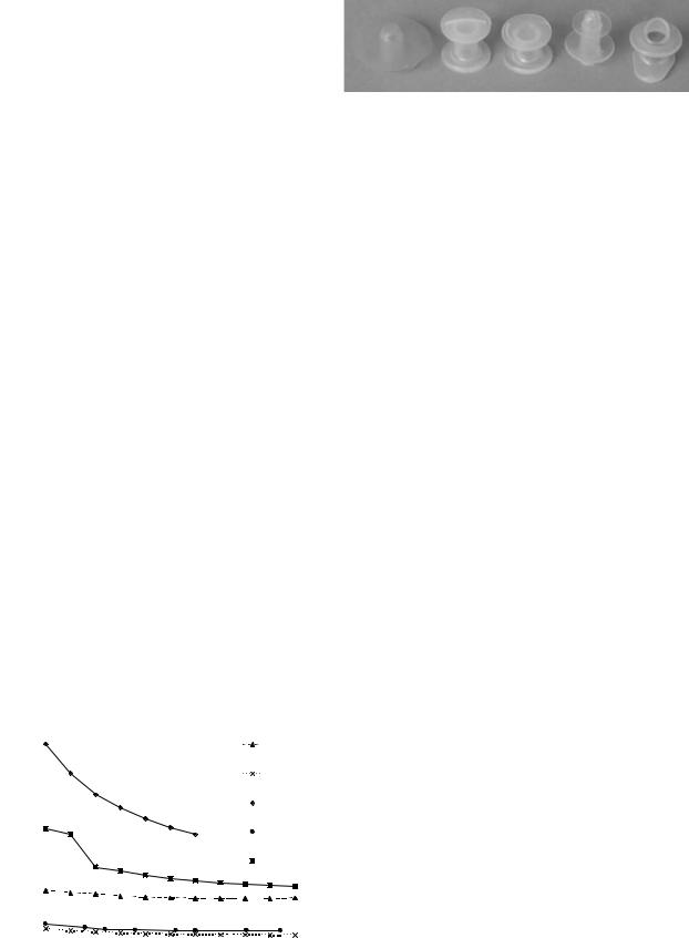
Figure 13. Examples of fixed commercial prosthesis. (Staffieri,

and causes the mucosal tissue tovibrate. The resulting

Groningen standard, Groningen low pressure, Panje, Provox).

sound can be modulated by the mouth, teeth, oral cavity,


and so on, to produce the new voice.


Most speakers that have prosthesis do not have difficul-

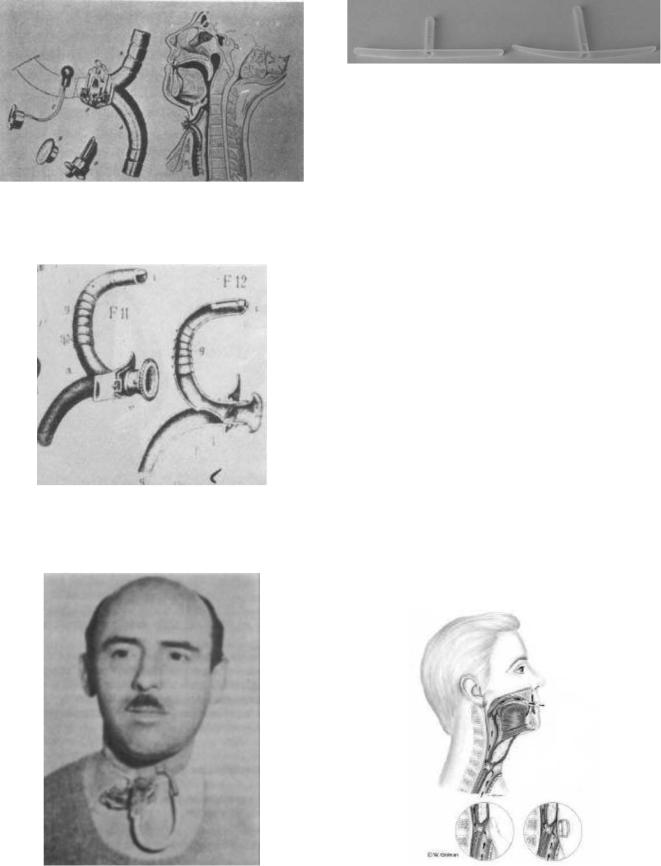
tracheal retention collar is connected to the mucosa (or

ties with articulation, rate of speech, or phonatory duration.

tracheal flange), a hollow cylindrical tube (whose length


If esophageal speech depends on gulping or trapping air

depends on the patient’s physical characteristics) connect-

using the phonatory valve, the resulting speech depends on

ing the trachea to the esophagus, an endoesophageal

expiratory capacity. Voice quality is very good, and may

flange, and a dome (or hat) that closes the proximal endoe-

resemble the ‘‘original’’ voice.


sophageal end of the tube. Via the razor-thin slit (or


Poor digital occlusion of the tracheostoma as well as

esophagus exit), the hat enables airflow to pass from the

poor tracheostoma valve adherence allows pulmonary air

trachea to the esophagus when there is a positive differ-

to escape from the stoma prior to its diversion through the

ential pressure, and prevents the reverse flow of liquid (or

prosthesis into the oesophagus for voice production. In fact,

food) when the differential pressure becomes negative. The

the bleeding off of pulmonary air limits phonatory duration

arrows represent the airflow paths.


and, therefore, the number of words that can be spoken.


Hat shape and the extension of the razor-thin slit can


The one-way valve design of the prosthesis prevents

differ according to valve type. The razor-thin slit may be

aspiration (of food and liquid) from the esophagus to the

located at the base of the hat (Staffieri, Groningen low

trachea. An example of a phonatory valve is shown in

pressure), at the center of the hat (Panje, Groningen

Fig. 12 (11,12). The prosthesis illustrated in this sketch

standard), or inside the hollow tube (Provox, Blom-Singer).

consists of an air-flow tracheal entry, whereby an endo-


Though valve geometry and shape may vary, the oper-


ating principle remains the same.


Several commercial prostheses are shown in Fig. 13:


from left to right, they include the Staffieri, Groningen


standard, Groningen low pressure, Panje, and Provox types.


Fixed and removable prostheses are available in differ-


ent lengths, which usually range from 6 to 12 mm to enable


the surgeon to select the dimensions that are best suited to


the patient’s physical characteristics, for example, poster-


ior tracheoesophageal wall thickness.


To compare valve performance in the laboratory, most


authors use valve airflow resistance (7,11), which is defined


as the ratio of pressure to flow-rate. Figure 14 show an


example of resistance versus flow-rate characteristics


obtained with experimental tests on commercial valves (11).


Low resistance allows air to pass freely though the


Figure 12. Sketch of phonatory valve or prostheses.

prosthesis with little effort on the part of the patient, and


80


Staffieri


/s)]

70


Provox


60


3

40


pressure


[kPa/(dm


50


Groningen


standard


Resistance


Groningen low


30


Panje


20


10


0


0

0,05

0,1

0,15

0,2

0,25

0,3

0,35


Flow-rate [dm3/s (ANR)]


Figure 14. Resistance of commercial valves.