

- •VOLUME 4
- •CONTRIBUTOR LIST
- •PREFACE
- •LIST OF ARTICLES
- •ABBREVIATIONS AND ACRONYMS
- •CONVERSION FACTORS AND UNIT SYMBOLS
- •HYDROCEPHALUS, TOOLS FOR DIAGNOSIS AND TREATMENT OF
- •HYPERALIMENTATION.
- •HYPERBARIC MEDICINE
- •HYPERBARIC OXYGENATION
- •HYPERTENSION.
- •HYPERTHERMIA, INTERSTITIAL
- •HYPERTHERMIA, SYSTEMIC
- •HYPERTHERMIA, ULTRASONIC
- •HYPOTHERMIA.
- •IABP.
- •IMAGE INTENSIFIERS AND FLUOROSCOPY
- •IMAGING, CELLULAR.
- •IMAGING DEVICES
- •IMMUNOLOGICALLY SENSITIVE FIELD–EFFECT TRANSISTORS
- •IMMUNOTHERAPY
- •IMPEDANCE PLETHYSMOGRAPHY
- •IMPEDANCE SPECTROSCOPY
- •IMPLANT, COCHLEAR.
- •INCUBATORS, INFANTS
- •INFANT INCUBATORS.
- •INFUSION PUMPS.
- •INTEGRATED CIRCUIT TEMPERATURE SENSOR
- •INTERFERONS.
- •INTERSTITIAL HYPERTHERMIA.
- •INTRAAORTIC BALLOON PUMP
- •INTRACRANIAL PRESSURE MONITORING.
- •INTRAOCULAR LENSES.
- •INTRAOPERATIVE RADIOTHERAPY.
- •INTRAUTERINE DEVICES (IUDS).
- •INTRAUTERINE SURGICAL TECHNIQUES
- •ION-EXCHANGE CHROMATOGRAPHY.
- •IONIZING RADIATION, BIOLOGICAL EFFECTS OF
- •ION-PAIR CHROMATOGRAPHY.
- •ION–SENSITIVE FIELD-EFFECT TRANSISTORS
- •ISFET.
- •JOINTS, BIOMECHANICS OF
- •JOINT REPLACEMENT.
- •LAPARASCOPIC SURGERY.
- •LARYNGEAL PROSTHETIC DEVICES
- •LASER SURGERY.
- •LASERS, IN MEDICINE.
- •LENSES, CONTACT.
- •LENSES, INTRAOCULAR
- •LIFE SUPPORT.
- •LIGAMENT AND TENDON, PROPERTIES OF
- •LINEAR VARIABLE DIFFERENTIAL TRANSFORMERS
- •LITERATURE, MEDICAL PHYSICS.
- •LITHOTRIPSY
- •LIVER TRANSPLANTATION
- •LONG BONE FRACTURE.
- •LUNG MECHANICS.
- •LUNG PHYSIOLOGY.
- •LUNG SOUNDS
- •LVDT.
- •MAGNETIC RESONANCE IMAGING
- •MAGNETOCARDIOGRAPHY.
- •MANOMETRY, ANORECTAL.
- •MANOMETRY, ESOPHAGEAL.
- •MAMMOGRAPHY
- •MATERIALS, BIOCOMPATIBILITY OF.
- •MATERIALS, PHANTOM, IN RADIOLOGY.
- •MATERIALS, POLYMERIC.
- •MATERIALS, POROUS.
- •MEDICAL EDUCATION, COMPUTERS IN
- •MEDICAL ENGINEERING SOCIETIES AND ORGANIZATIONS
- •MEDICAL GAS ANALYZERS
- •MEDICAL PHOTOGRAPHY.
- •MEDICAL PHYSICS LITERATURE
- •MEDICAL RECORDS, COMPUTERS IN
- •MICROARRAYS
- •MICROBIAL DETECTION SYSTEMS
- •MICROBIOREACTORS
- •MICRODIALYSIS SAMPLING
- •MICROFLUIDICS
- •MICROPOWER FOR MEDICAL APPLICATIONS
- •MICROSCOPY AND SPECTROSCOPY, NEAR-FIELD
- •MICROSCOPY, CONFOCAL
- •MICROSCOPY, ELECTRON
- •MICROSCOPY, FLUORESCENCE
- •MICROSCOPY, SCANNING FORCE
- •MICROSCOPY, SCANNING TUNNELING
- •MICROSURGERY
- •MINIMALLY INVASIVE SURGICAL TECHNOLOGY
- •MOBILITY AIDS
- •MODELS, KINETIC.
- •MONITORING IN ANESTHESIA
- •MONITORING, AMBULATORY.
- •MONITORING, FETAL.
- •MONITORING, HEMODYNAMIC
- •MONITORING, INTRACRANIAL PRESSURE
- •MONITORING, NEONATAL.
- •MONITORING, UMBILICAL ARTERY AND VEIN
- •MONOCLONAL ANTIBODIES
- •MOSFET.
- •MUSCLE ELECTRICAL ACTIVITY.
- •MUSCLE TESTING, REHABILITATION AND.
- •MUSCULOSKELETAL DISABILITIES.
428 MICROPOWER FOR MEDICAL APPLICATIONS
MICROPOWER FOR MEDICAL APPLICATIONS
JI YOON KANG
Korea Institute of Science and
Technology
Seoul, Korea
INTRODUCTION
Generally, micropower is the local generation of electricity by small-scale generators, which locates the end point. As the recent development of the microelectromechanical system (MEMS), as well as CMOS electronics technology, has been reducing the size and cost of biomedical devices, the research of micropower became important for implantable biomedical devices since they require internal selfsustained power sources.
As for biomedical devices, micropower is an internal or external power source to supply energy for active devices, which replaces an organ’s function or treats diseases. The examples of active implantable devices that consume energy are cardiac pacemakers, cardiac defibrillators, muscle stimulators, neurological stimulators, cochlear implants, and drug pumps (1). Hence, in this article the term micropower describes rather tiny power supplying devices for miniatur-
ized sensors, actuators, and electric devices, whose size is > or < 1 cm3.
The low power electrical actuator, such as a pacemaker or neuronal stimulator, requires tens of microwatts intermittently and their power source is usually a lithium iodine battery that lasts from 5–8 years. Usually, the stand-by current of a pacemaker is 1 mA in waiting mode and its pulse current is 6 mA. One example of a specification for a pacemaker pulse is in the range of 25 mJ ( 11 mA at 2.2 V with a 1 ms discharge) and the capacity of the battery is 2 Ah at typical rating (2). The volume of a pacemaker is20 mL and the volume occupied by the battery is about one-half of the total volume, 10 mL. Hence, the energy density (energy/volume) and reliability are important factors in the lifetime of the device.
An internal battery that is hermetically sealed in these devices can operate them with low power consumption; however, other implantable devices have radically different power requirements. Implantable cardioverter defibrillators demand the energy of 15–40 J providing six orders of magnitude larger than that of a pacemaker even though the pulses are less frequent. The current from a lithium silver vanadium battery is charged in an internal capacitor and the pulse of 1–2 A of current is fired. Electromechanical actuator like drug pumps demand more current than a lithium ion battery can deliver since it needs to overcome the high pressure in the chamber. The examples of drug pumps are insulin pumps, pain reliever, and an cerebrospinal fluid pump. A high current implantable battery should have low source impedance, such as lithium thionyl chloride, lithium carbon monofluoride, or lithium silver vanadium oxide.
Other future application are in wireless sensors, including physiological, chemical, or physical sensors embedded in an encapsulated environment. Miniaturized sensor
consumes < 100 mW and a radio frequency (rf) transmitter consumed 10 mW intermittently. Since most of the power is used for communication, some research groups are developing several low power wireless transmission protocols (3,4). Hence, less power will be necessary for a sensor transmitter as technology evolves.
Some groups investigated more efficient and reliable batteries. To enhance their efficiency and lifetime, potential alternatives of the conventional batteries studied, such as a microfabricated battery, microfabricated fuel cell, and biofuel cell. Microelectrical system technology reduces the size of the primary battery and microfluidic galvanic cell (5), water activated microbatteries (6), and Li-ion microbatteries were demonstrated. The fuel cell attracts much attention since it has a high efficiency, high power, and low pollution rate. Research on fuel cells focus on high power applications,suchastheautomobileand portableelectronics, like laptop computers and cellular phones (7). Recently, micromachining technologies employed as a method to fabricate miniature fuel cells (8–11) and their size became smaller than a button cell battery (12) with high power. Enzyme-based glucose/O2 biofuel cells were reported by several groups (13) and a miniaturized all (14) was reported that is < 1 mm3, with although a power of 4.3 mW. Since glucose is available in all tissues and organs, it is advantageous in implanted medical sensortransmitters.
Although a primary battery as well as a rechargeable battery is an important tool that supplies reliable power to implant devices, the continuous power of the battery decreases with time, and after 5 years they will not supply enough power (15). Power delivery with an rf transmission can extend the lifetime and continuously deliver high power. In the case of a cochlear implant, an external device provides power and data through electromagnetic field coupling; however, it needs accurate positioning of the external device and may cause rf interference and heating of the tissue.
Therefore, many research groups are paying attention to microfabricated power scavenging devices as an auxiliary power source to recharge the battery with no external power. Ambient energy sources are body heat or movement of the human body. Piezoelectric material (16–18), capacitance change (19–24), and inductive coil (25–27) convert vibration or human motion into electrical energy. The generation by high frequency vibration is not suitable for implant devices since vibration of the human body is in the range of tens of hertz. Hence, energy conversion using vibration of low frequency can be integrated with implant devices.
Thermoelectric generators that convert temperature differences of the human body or combustion engine to electricity were reported (28,29). Another conversion method is the thermophotovoltaic power generator (30,31), which combines the combustion engine and solar cell. However, integrating a power generation device into an implant device has some limitations due to biocompatibility. Power generation with a high temperature like the combustion engine or thermovoltaic metoid, cannot be implemented in the inside of the human body due to the heating of tissues. Thermoelectric generation using body heat is promising for the implantable device. However, this article includes the review on the other portable power sources like the micro-
combustion engine, because those are also useful for a portable diagnosis system. The recent development of microfluidics and miniaturized biosensors enables point-of-care testing devices to be on the market in the near future. A microheat engine is highly efficient in energy conversion and will be useful as a portable medical equipment.
A good review article on micropower for wireless sensor networks was reported (20,32). It lists the candidates of portable power sources and compares the energy density for the battery and power density for a power generator. This article reviews the existing and potential micropower sources in view of medical applications from tiny sensors embedded in the human body to portable medical electronic devices.
MICROBATTERY
For a long time, the battery was a major energy source in portable electronic devices and it has evolved from Zn/ MnO2 to the Zn/air cell since 1900. Electrochemical power sources were developed in response to the needs of the flashlight, automotive starter, mobile electronics, and laptop computers. These days, there is a tremendous need for portable electronics demanding smaller, lighter, and longer lived batteries. Hence, many researches are on the way to making microfuel cell or microfabricated batteries using various kinds of electrochemical power. This section will briefly review microbatteries including fuel cells, biofuel cells, and micromachined batteries.
Microfuel Cell
Although the energy density of conventional batteries has
been increasing |
1from 500 Wh L 1 for the Ni/Cd battery |
|||
to 1500 Wh |
|
L |
a |
|
|
|
for the Li/C–CoO2 battery, there is |
1 |
|
large jump for the air-cathode fuel cells of 4500 Wh L |
|
|||
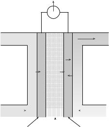
using hydrogen, hydrocarbon, and metals (7). The proton exchange membrane fuel cell (PEMFC) depicted in Fig. 1 is one of the promising techniques for fuel cell, which was
Power
Water
|
H2O |
H2 |
H+ |
|
O2 |
Hydrogen |
|
|
|
|
|
|
|
Oxygen |
||
|
|
|
||||||||
|
|
|
|
|
|
|||||
|
|
|
||||||||
|
|
|
|
|
|
|
|
|
|
|
|
|
|
|
|
|
|
|
|
|
|
|
|
|
|
|
|
|
|
|
||
|
|
|
|
|
|
|||||
|
|
Anode |
Electrolyte Cathode |
|||||||
Figure 1. Schematic of a PEM fuel cell.
MICROPOWER FOR MEDICAL APPLICATIONS |
429 |
implemented in miniaturization. Power sources for the automobile or the portable electronics of a huge market have been a main concern of fuel cell research because of the advantage of high efficiency and easy rechargeability. However, these days, in response to the demand of low power application, many miniaturized fuel cells are under study. Miniature fuel cells with a series path in a flipflop configuration was fabricated in a planar array and a fourcell prototype was produced, 40 mW cm 1 (33). Yu (11) added microfluidic channels using anisotropic wet etching of silicon to the flipflop configuration and measured a peak power density of 190 mW cm 2. They also reported that the flipflop fuel cell was constructed on printed circuit board (PCB) and that they achieved the area power density of >700 mW cm 2. Wainright (12) fabricated on-board hydrogen storage with multiple coplanar fuel cells in series on ceramic substrates. They stored hydrogen in the form of the stabilized aqueous solutions of sodium borohydride (NaBH4) or a metal hydride material, such as LaAl0.3Ni4.7. The energy density of microfabricated fuel cells did not exceed that of a Li/MnO2 coin cell, but it had the advantage of higher power and compatibility with other microelectronic, microelectromechanical, or microfluidic devices. A polymer microfluidic channel was applied to a fuel cell using PDMS (10) and poly (methyl methacrylate) (PMMA)
(8). They achieved a comparable area power density with a silicon based one. Whitesides and co-workers (9) also reported a membraneless vanadium redox fuel cell using a laminar flow property in a microfluidic channel with 200 mW cm 2. As for the commercialization, MTI microfuel cells and Manhattan Scientifics are making portable fuel cells using direct methanol fuel cell (DMFC) and Medis technology announced direct liquid fuel cell (DLFC) for handheld devices. Miniaturized fuel cells are promising for implantable medical devices with a high power requirement and it has the advantage of a longer lifetime and less charging time than a conventional battery.
However, PEM fuel cells do not fit well with the implantable microdevices with high power and a long life application because the refill of a hydrogen fuel cell is not easy when it is sealed in the human body. As an alternative fuel cell, the biofuel cell is a strong candidate for a low power embedded device like a microbiosensor. Although a biofuel cell is not capable of high power, the easy availability of fuel (glucose) gives it a long operation time. Enzyme-based glucose/O2 biofuel cells were studied since 1980s (13) and Heller and co-worker (34) demonstrated the feasibility of a membraneless miniature biofuel cell as an implanted micropower source. Its chemical reaction is described in equations 1 and 2.
glucose ! glucolactone þ 2Hþ þ 2e |
(1) |
O2 þ 4Hþ þ 3e ! 2H2O |
(2) |
Some fuel cell components, such as case, membrane, ion conductive electrolyte, and plumbing was removed in the biofuel cell and its size became <1 mm2. The power of the biofuel is 4.3 mW with 0.52 V and it is suitable for an implanted devices because of tiny volume and abundant glucose inside of human body. Moor et al. (35) developed a microfluidic chip based ethanol–oxygen biofuel cell, which
430 MICROPOWER FOR MEDICAL APPLICATIONS
produced 18 mW with 0.34 V and is applicable to integrate the biofuel cell and the microfluidic chip.
Micromachined Battery
A microfabricated battery usually refers to a thin-film battery, however, recently some research groups are studying MEMS-based microbatteries. Integration of microbatteries with CMOS electronics or an MEMS device is easy and can be fabricated on a chip with a device. Since the microbatteries main concern is power output due to limitation of surface rather than the capacity, most research activities are focused on increasing power to out perform maintaining capacity.
As for thin-film batteries, Bates et al. (36) at Oak Ridge National Laboratory reported a thin-film secondary battery, which was made up of lithium and lithium ion. The thickness is tens of mm and the area is in the cm2 range. Its continuous current output is 1 mA cm 2. Pique et al. (37) constructed primary Zn–Ag2O and secondary Li ion microbatteries in plane using laser direct-write with a capacity of 100 mAh cm 2.
Other than classical thin-film batteries, several micromachined MEMS batteries were developed. They try to integrate power sources with microelectronic circuits and microsensors. Prof. Lin at UC Berkeley proposed a wateractivated battery with 1.86 mWh in the area of 12 12 mm for lab-on-a-chip application (6) that overcomes the corrosiveness of the micromachined batteries with sulfuric acid and hydrogen peroxide (38). Andres (5) devised a pump integrated with a micropower source, in which microfluidic galvanic cells supplied power to heat up the two-phase fluid for pumping. The capacity of the micromachined battery is lower than that of a thin-film battery yet, its application is restricted to the integrated power for a micromachined implantable device.
MICROPOWER GENERATOR
A micropower generator scavenges energy from devices. The energy sources are mechanical (vibration and human body movement), thermal (temperature difference), and
solar energy. Thermoelectric devices convert the temperature difference to electricity and the photovoltaic cell collects solar energy. A MEMS-based power generator scavenges energy from the vibration in the mechanical structure or human body movements.
Thermoelectric Generator
Thermoelectric generation using the Seebeck effect was widely studied. This effect was discovered in 1821 by the physicist, Jonn Seebeck. It is the same phenomenon with a thermocouple where the temperature difference produces electricity or work. Although a thermoelectric power generator is an old technique and is commercially available in various sizes in the market, recent research focuses on making miniaturized low power thermoelectric microgenerators using microfabrication. Cost-effective fabrication technology was developed using electroplated structures with an epoxy film (28) and nanowire arrays by electrochemical deposition was implemented to improve thermoelectrical properties (29). Reportedly, several companies announced a thermoelectric generator using body heat. Applied Digital Solutions (39) announced a thermoelectric generator called ThermoLife, which produced a power of 49 mW from a temperature difference of 5 8C in 0.5 cm2. Biophan technologies (40) also announced a biothermal power source as shown in Fig. 2 for implantable devices like a pacemaker and defibrillator (41). They aim to produce 100 mW at 3 V with 1 8C temperature difference. A different scheme converting thermal energy to electricity is piezoelectric generator actuated by thermal expansion of two-phase working fluid (42). Although they produced up to 56 mW at its resonance frequency of 370 Hz, a practical application needs the careful design of a heat-transfer mechanism because the temperature is required to oscillate at a resonance frequency of structure. A thermoelectric generator has a well-established technology and its operation is relatively stable; however, note that the temperature difference inside the human body is < 1 8C. The temperature gradient is maximum at the skin surface and will limit the location of the thermoelectric power generator.
|
p-type Semiconductors pallets |
|
|
Heat absorbed |
|
Ceramic |
(Cold side) |
|
n-type Semiconductors pallets |
||
substrate |
Conductor
Positive(+)
Heat rejected (Hot side)
Negative(−)
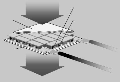
Figure 2. Principles of thermoelectric power source (Biophan).
microWatts
MICROPOWER FOR MEDICAL APPLICATIONS |
431 |
Continuous Power / cm3 vs. Life Several Energy Source
1000 |
|
Solar |
|
Lithium |
|
|
|
|
100 |
Alkaline |
Vibrations |
10 |
|
|
|
|
|
|
|
|
|
|
|
|
|
|
|
|
Zinc air |
|
Lithium rechargeable |
|
|
|
|
|
|||
1 |
NiMH |
|
|
|
|
|
|
|
|
||||
|
|
|
|
|
|
|
|
|
|
|
|||
0 |
|
|
|
|
|
|
|
|
|
|
|
|
|
0 |
0.5 |
1 |
1.5 |
2 |
2.5 |
3 |
3.5 |
4 |
4.5 |
5 Figure 3. Comparison of power density |
|||
|
|||||||||||||
|
|
|
|
|
|
Years |
|
|
|
|
|
from vibrations, solar and batteries (21). |
|
Power Generation with Ambient Vibration
Conversion of a mechanical vibration to electric power has been studied from the mid 1990s (43) using MEMS, while thermal and solar energy were exploited to generate electricity long ago. They changed vibration to electrical energy using piezoelectric, electromagnetic, and electrostatic generations.
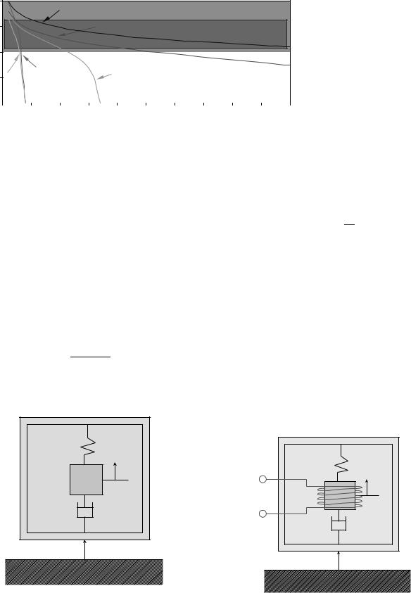
The frequency of vibration in an ambient environment ranges from 60 to 400 Hz and for the microwave oven the acceleration was 2.25 m s 2 at a resonance frequency of 120 Hz (15). Shad (21) suggested a graph comparing the power density of power scavenging and batteries as a function of time (Fig. 3). Power density in the vibration of machining center or microwave oven becomes larger than conventional batteries after 3 or 4 years, which means the waste vibration energy is not negligible. Williams and Yates (43) presented a general model in equation 3 for the power of external vibration as depicted in Fig. 4, when a mass is moved at a resonant frequency of vn.
ztmY2v3
P ¼ o n z (3) 4ðzt þ zoÞ2
where m is mass, and Yo is the maximum extent that the mass can move, zt and zo denote a damping factor both
in the transducer structure and in the environment (e.g., air).
Electromagnet Conversion. Motion between the inductor and the permanent magnet induces an electromagnetic current in the inductor coil, as shown in Fig. 5 (25). The induced voltage, V, in the coil is given by equation 4.
V ¼ NBl |
vn |
(4) |
2z |
where N is the number of turns in the coil, B is the strength of the magnetic field, l is the length of coil, and z is the displacement of the magnet in the coil. This type of generator was fabricated with laser micromachining by Ching et al. (27) in 1 cm3 volume and generated a 4.4 V peak-to-peak with a maximum rms power of 830 mW. Glynne-Jones et al. (44) at the University of Southampton, derived 157 mW on average new car engine. Perpetuum Ltd., a spin-off company from the University of Southampton, produced an electromechanical microgenerator. That generated up to 4 mW and its operation frequency was 30–350 Hz. The vibration amplitude was 200 mm with 60–110 Hz and demonstrated a wireless temperature sensor transmitter system. This result showed electromagnetic conversion is feasible in low frequency vibration and is promising if it is compatible with silicon micromachining.
k |
z |
m |
b |
y |
|
k |
+ |
|
|
z |
|
m |
− |
Permanent |
b |
magnet |
|
y |
Figure 4. Schematic analysis for mechanical movement of a power generator with external vibration.
Figure 5. Schematic of an electromagnetic conversion device.

432 MICROPOWER FOR MEDICAL APPLICATIONS
Anchor
PZT layer
Silicon layer
Mass
Figure 6. Structure of a piezoelectric cantilever for power generation.
Piezoelectric Conversion. The piezoelectric effect states that the deformation in the material produces an electrical charge due to the separation of charge within crystal structures. The most widely used piezoelectric material is PZT (lead zirconate titanate) in ceramic materials and PVDF [poly (vinylidene fluoride)] in polymers. Several groups are studying the piezoelectric cantilever with seismic mass (Fig. 6). The constitutive equations of piezoelectric materials are expressed in equation 5.
s ¼ Yðd d31EÞ D ¼ d31s þ eE |
(5) |
where s is the mechanical stress, d is the mechanical strain, Y is Young’s modulus, d31 is the piezoelectric strain coefficient, D is the charge density, E is the electric field, and e is the dielectric constant of the piezoelectric material. The piezoelectric coefficient links the mechanical stress–strain to the electrical charge equation. If the circuit is open (D ¼ 0), the voltage across the piezoelectric layer is described in equation 6.
V |
¼ |
d31s |
t |
piezo |
(6) |
|
e |
|
|||
where tpiezo is the thickness of the piezoelectric layer. The charge collected on the electrode is integrated on the area of the surface with no load condition as in equation 7
ZZ
Q ¼ D dA ¼ d31s dA |
(7) |
When the impedance in the load circuit is pure resistance, the time-averaged power can be derived in Ref. 17 with the geometry of a cantilever. White and co-workers (16) presented a thick-film PZT generator, and the maximum power is 2 mW. According to the analysis of Lu et al. (17), a 5 mm long PZT cantilever can generate >100 mW with the amplitude of >20 mm at 3 kHz resonance. Roundy (15) demonstrated a piezoelectric converter of 1 cm3 in volume, that is 1.75 cm in length. It generated 200 mW and is driven with vibrations of 2.25 m s 2 at 120 Hz. A microfabricated PZT cantilever generator driven by a bubble was studied by Kang et al. (44), and a few picowatt was generated with one tiny cantilever at 30 Hz and tens of mW is expected on a 1 cm2 surface (46). If the design, material, and fabrication are optimized, piezoelectric powergeneration will produce hundreds of microwatts with a volume of 1 cm3.
|
SW1 |
|
|
|
|
|
SW2 |
|||
Vin + |
Cv |
|
|
|
Cpar |
|
Cstar |
|||
|
|
|
|
|
|
|
|
|
|
|
|
|
|
|
|
|
|
|
|
|
|
−
Figure 7. Circuit representation for an electrostatic converter (15).
Electrostatic Conversion. The electrical energy in a capacitor is given in equation 8.
E ¼ |
1 |
QV ¼ |
1 |
CvV2 |
¼ |
1 |
Q2 |
(8) |
|
|
|
|
|
|
|||||
2 |
2 |
2 |
Cv |
||||||
When the charge, Q, is constant, if the variable capacitance, Cv, is decreased the total energy E in the capacitor will increase. The MEMS structure can change the capacitance Cv with an external vibration, and stored energy in the capacitor transfers to energy storage. In the beginning, the external power source Vin initiates the charging process as in Fig. 7 (15). When Cv is maximum, SW1 is closed and the variable capacitance Cv is charged. While vibration changes capacitance Cv, all switched are open. When Cv reaches a minimum, SW2 is turned on and the energy in Cv is transferred to a storage capacitance Cstor. The disadvantage of electrostatic conversion is that it needs an external voltage source and switching circuit. The voltage across the storing capacitance is given in equation 9.
Estor ¼ |
1 |
ðCmax CminÞVmaxVin |
ðRef: 47Þ (9) |
2 |
where Vmax is the maximum voltage across the capacitor Cv. Switching the circuit is realized using a diode and field effect transistor (FET) switch. Meninger et al. (47) made a comb-type variable capacitance with an in-plane overlap type with a 7 mm gap and a 500 mm depth using the 0.6 mm CMOS process. They produced a power of 8 mW with an ultralow power delay locked loop (DLL)-based system. Miao et al. (23) reported an out-of-plane variable capacitor with a gap closing type that varies from 100 pF to 1 pF. A periodic voltage output of 2.3 kV (10 Hz) was generated when the charging voltage was 26 V, which implies that a power of 24 mW (2.4 mJ cycle 1) can be produced. Mitchenson et al. analyzed architectures for vibration-driven micropower generators (26) and they fabricated a prototype of an electrostatic power generator producing 250 V cycle 1 that corresponds to 0.3 mJ cycle 1 (22). Other studies demonstrated polymer capacitor (24) and a liquid rotor power generator with a variable permittivity producing 10 mW (19). Recent developments in electrostatic generators
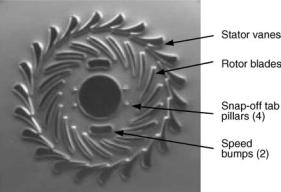
Figure 8. SEM of microturbine of MIT (52).
demonstrated that it is feasible and manufacturable with MEMS and that it has the advantage of a low frequency application like human body movement. However, the generated voltage is very high and should be managed for the implant application. Since it is compatible with the CMOS process and the variable capacitor is a well-established MEMS device, it is very promising as an integrated power generator with a sensor and transmitter.
Microheat Engine
A microheat engine is hard to be implanted in the human body, but it is promising as an external power source for portable medical equipment. A tiny internal combustion engine, made by precise machining, such as electrical discharge machining (EDM) or MEMS, may have a much higher density than a primary battery since the energy density of fossil fuel is 45 MJ kg 1, while that of Li ion batteries are at most 0.5 MJ kg 1 (48). Microturbine by EDM (48), Microrotors by deep reactive ion etching (DRIE) (49), heat engine (42) and reciprocating devices (50) was reported for electric power generation.
Several groups are working on a microheat engine, since fossil fuel offers a much higher energy density. Since the generated power is expected to generate 10–20 W, it is suitable for high power application. The Stirling engine (51), the reciprocal combustion engine (50), the Wankel motors, and gas turbines are reported. One of the first microengine projects was started at MIT (52) and the microfabricated turbine with a 4.2 mm diameter was illustrated in Fig. 8. Massachusetts Institute of Technology has been working on making microheat engines with a turbo charger and Georgia tech is collaborating with MIT on a magnetic generator (53). Allen and co-workers (54) at Georgia Institute of Technology generated a direct current (dc) electric power of 1.1 W with microfabricated windings at 120,000 rpm, although it was not integrated with a heat engine. Peirs et al. (48) made a microturbine by EDM and that tested to speeds of 160,000 rpm and produced a mechanical power of 28 W and an electrical power of 16 W. A miniaturized heat engine is still in the initial stage and no demonstration of power generation using a heat engine was reported. The heat engine would be very useful for high power applications such as portable
MICROPOWER FOR MEDICAL APPLICATIONS |
433 |
analytical equipment. Another scheme of a heat engine is thermophotovoltaic power generation (30,31). They converted the heat radiation in a SiC microcombustor to electric energy using photovoltaic cells, which is <1 cm2 and produced a power of 1.02 W with 2.28 V.
CONCLUSION
This article reviews micropower devices for medical implantable devices and portable medical device. Since the micropower devices have their own characteristics, there is no winner among them. When a selecting a micropower system for a specific application, one should consider the energy capacity, power, volume, voltage, and compatibility of fabrication with microelectronic device.
Currently, primary or secondary batteries with external power transmission are a main power storage for a low power implanted device. As the application of implant devices is diversified and requires a high power output and longer lifetime, new battery like fuel cell, or biofuel will replace conventional battery system in the future. Furthermore, when power transmission through the skin is impossible due to the attenuation of transmission, integrated power generation device will be an alternative.
Most micropower generators are still in their infancy and they need much more study to be implemented in implant device. Research results on micropower generators showed only the feasibility of concept and their power is much less than the requirement. Hybrid micropower supplies (55) or integrated power system would be strong candidates for long battery life applications. The promising application of active implant device will be glucose sensor and the artificial pancreas for the treatment of diabetes and the ubiquitous bioor environmental sensor network. Since there is strong demand in the market, it is believed that micropower system will be available in near future.
BIBLIOGRAPHY
1.Soykan O. Power sources for implantable medical devices. Business briefing: Medical device manufacturing and technology. 2002, p 76–79.
2.Mallela VS, Ilankumaran V, Rao NS. Trends in Cardiac Pacemaker Batteries. Indian Pacing Electrophysiol J 2004;4: 201–212.
3.Zhong LC, Shah R, Guo C, Rabaey J. An Ultra-Low Power and Distributed Access Protocol for Broadband Wireless Sensor Networks. Presented at IEEE Broadband Wireless Summit, Las Vegas (NV); 2001.
4.David Culler DE, Srivastava M. Overview of Sensor Networks. IEEE Comput Special Issue Sensor Networks 2004; 41–49.
5.Cardenas-Valencia A, et al. A microfluidic galvanic cell as an on-chip power source. Sensors Actuator B 2003;95:406–413.
6.Sammoura F, Lee Kb, Lin L. Water-activated disposable and long shelf life microbatteries. Sensors Actuators A 2004;111: 79–86.
7.Dyer CK. Fuel cells for portable applications. J Power Sources 2002;106:31–34.
8.Chan SH, Nguyen N-T, Xia Z, Wu Z. Development of a polymeric micro fuel cell containing laser-micromachined flow channels. J Micromech Microeng 2005;15:231–236.
434MICROPOWER FOR MEDICAL APPLICATIONS
9.Ferrigno R, et al. Membraneless Vanadium Redox Fuel Cell uisng Laminar Flow. J Am Chem Soc 2002;124: 12930–12931.
10.Shah K, Shin WC, Besser RS. Novel microfabrication approaches for directly patterning PEM fuel cell membranes. J Power Sources 2003;123:172–181.
11.Yu J, Cheng P, Maa Z, Yi B. Fabrication of a miniature twin-fuel-cell on silicon wafer. Electrochim Acta 2003;48: 1537–1541.
12.Wainright JS, Saniell RF, Liu CC, Lit M. Microfabricated fuel cells. Electrochem Acta 2003;48:2869–2877.
13.Barton SC, Gallaway J, Atanassov P. Enzymatic Biofuel Cells for Implantable and Microscale Devices. Chem Rev 2004;104: 4867–4886.
14.Heller A. Miniature biofuel cells. Phys Chem Chem Phys 2004;6:209–216.
15.Roundy SJ. Energy Scavenging for Wireless Sensor Nodes with a Focus on Vibration to Electricity Conversion. Mechanical Engineering. Berkeley: The University of California; 2003 p 287.
16.Glynne-Jones P, Beeby SP, White NM. Towards a piezoelectric vibration-powred microgenerator. IRR Proc-Sci Meas Technol 2001;148:68–72.
17.Lu F, Lee HP, Lim SP. Modeling and analysis of micro piezoelectric power generators for micro-electromechanical- systems applications. Smart Mat and Structure 2004;13: 57– 63.
18.Shenck N, Paradiso JA. Energy Scavenging with Shoemounted piezoelectronics. IEEE Micro 2001;21:30–42.
19.Boland JS, Messenger JDM, Lo HW, Tai YC. Arrayed liquid rotor electret power generation. Presented at IEEE MEMS 2005, Miami(FL) 2005.
20.Roundy S, Steingart D, et al. Power Sources for Wireless Networks. Presented at Proc. 1st European Workshop on Wireless Sensor Networks (EWSN’04), Berlin(Germany). 2004.
21.Roundy S, Wright PK, Rabaey J. A study of low level vibrations as a power source for wireless sensor nodes. Comp Commun 2003;26:1131–1144.
22.Mitcheson PD, et al. MEMS electrostatic micropower generator for low frequency operation. Sensors and Actuator A 2004;115:523–529.
23.Miao P, Holmes AS, Yeatman EM, Green TC. MicroMachined Variable Capacitors for Power Generaton. Presented at Electrostatics’03, Edinburgh(UK). 2003.
24.Arakawa Y, Suzuki Y, Kasagi N. Micro seismic power generator using electret polymer film. Presented at The Fourth International workshop on Micro and Nanotechnology for power generation and energy conversion applications Power MEMS 2004, Kyoto(Japan). 2004.
25.Li WJ, et al. A micromachined vibration-induced power generator for low power sensors of robotic systems. Presented at World Automation Congress: 8th International Symposium on Robotics with Applications, Hawaii 2000.
26.Mitcheson PD, Green TC, Yeatman EM, Holmes AS. Architectures for Vibration-Driven Micropower Generators. J Microelectomech Systems 2004;13:429–440.
27.Ching NNH, et al. A laser-micromachined multi-modal resonating power transducer for wireless sensing systems. Sensors Actuator A 2002;97:685–690.
28.Qu W, Plotner M, Fischer W-J. Microfabrication of thermoelectric generators on flexible foil substrates as a power source for autonomous microsystems. J Micromechan Microeng 2001; 11:146–152.
29.Wang W, Jia F, Huang Q, Zhang J. A new type of low power thermoelectric micro-generator fabricated by nanowire array thermoelectric material. Proc 22nd Int Conf Thermoelectrics 2003;682–684.
30.Wenming Y, et al. Effect of wall thickness of micro-combustor on the performance of micro-thermophotovoltaic power generators. Sensors Actuator A; in press, 2005.
31.Yang WM, et al. A prototype microthermophotovoltaic power generator. Appl Phys Lett 2004;84:3864–3866.
32.Pescovitz D. The power of small tech. Smalltimes 2002; 2.
33.Lee SJ, et al. Design and fabrication of a micro fuel cell array with flip-flop interconnection. J Power Sources 2002;112: 410–418.
34.Chen T, et al. A Miniature Biofuel Cell. J Am Chem Soc 2001;123:8630–8631.
35.Moore CM, Minteer SD, Martin RS. Microchip-based ethanol/ oxygen biofuel cell. Lab Chip 2005;5:218–225.
36.Bates JB, et al. Thin-film lithium and lithium-ion batteries. Solid State Ionics 2000;135:33–45.
37.Pique A, et al. Rapid prototyping of micropower sources by laser direct write. Appl Phys A Mat Sci Proc 2004;79:783–786.
38.Lee KB, Lin L. Electrolyte based on-demand disposable microbattery. Presented at IEEE MEMS 2002, Las Vega. 2002.
39.Applied Digital solutions, www.adsl.com.
40.Biophan technologies. Available at www.biophan.com/ biothermal.php.
41.MacDonald SG, Biothermal power source for implantable devices. US Patent 6,640,137, 2003.
42.Whalen S, et al. Design, Fabrication and testing of the P3 micro heat engine. Sensors Actuator A 2003;104:290–298.
43.Williams CB, Yates RB. Analysis of a micro-electric generator for microsystems. Sensors Actuator A 1996;52:8–11.
44.Glynne-Jones P, et al. An electromagnetic, vibration-powered generator for intelligent sensor systems. Sensors Actuators A 2004;110:344–349.
45.Kang J-Y, Kim H-J, Kim J-S, Kim T-S. Optimal design of piezoelectric cantilever for a micro power generator with microbubble. Presented at Microtechnologies in Medicine & Biology 2nd Annual International IEEE-EMB Special Topic Conference, Madison (WI). 2002.
46.Kang JY, Kim JS, Kim HY, Kim TS. Micro Power Generator with Piezoelectric Cantilever Driven By Micro Bubble. Sensors Actuator A submitted, 2005.
47.Meninger S, et al. Vibration-to-Electric Energy Conversion. IEEE Trans VLSI Systems 2001;9:64–76.
48.Peirs J, Reynaerts D, Verplaetsen F. A microturbine for electric power generation. Sensors Actuator A 2004;113: 86–93.
49.Miki N, Teo CJ, Ho LC, Zhang X. Enhancement of rotordynamic performance of high-speed micro-rotors for power MEMS applications by precision deep reactive ion etching. Sensors Actuator A 2003;104:263–267.
50.Lee DH, et al. Fabrication and test of a MEMS combustor and reciprocating device. J Micromech 2002;12:26–34.
51.Backhaus S, Swift GW. A thermoacustic Stirling heat engine. Nature (London) 1999;399:335–338.
52.Frechette LG, et al. Demonstration of a microfabricated highspeed turbine supported on gas bearings. Presented at Solid-state sensors and actuator workshop, Hilton head island, (SC). 2000.
53.Jacobson SA, et al. Progress toward a icrofabricated gas turbine generator for soldier portable power applications. Presented at 24th Army Science Conference, Orlando (FL). 2004.
54.Das S, et al. Multi-Watt electric power from a microfabricated permanent magnet generator. Presented at IEEE MEMS 2005, Miami(FL). 2005.
55.Harb J, LaFollete R, Selfridge R, Howell L. Microbatteries for self-sustained hybrid micropower supplies. J Power Sources 2002;104:46–51.
See also BIOTELEMETRY; COMMUNICATION DEVICES; MICROFLUIDICS.