

- •VOLUME 4
- •CONTRIBUTOR LIST
- •PREFACE
- •LIST OF ARTICLES
- •ABBREVIATIONS AND ACRONYMS
- •CONVERSION FACTORS AND UNIT SYMBOLS
- •HYDROCEPHALUS, TOOLS FOR DIAGNOSIS AND TREATMENT OF
- •HYPERALIMENTATION.
- •HYPERBARIC MEDICINE
- •HYPERBARIC OXYGENATION
- •HYPERTENSION.
- •HYPERTHERMIA, INTERSTITIAL
- •HYPERTHERMIA, SYSTEMIC
- •HYPERTHERMIA, ULTRASONIC
- •HYPOTHERMIA.
- •IABP.
- •IMAGE INTENSIFIERS AND FLUOROSCOPY
- •IMAGING, CELLULAR.
- •IMAGING DEVICES
- •IMMUNOLOGICALLY SENSITIVE FIELD–EFFECT TRANSISTORS
- •IMMUNOTHERAPY
- •IMPEDANCE PLETHYSMOGRAPHY
- •IMPEDANCE SPECTROSCOPY
- •IMPLANT, COCHLEAR.
- •INCUBATORS, INFANTS
- •INFANT INCUBATORS.
- •INFUSION PUMPS.
- •INTEGRATED CIRCUIT TEMPERATURE SENSOR
- •INTERFERONS.
- •INTERSTITIAL HYPERTHERMIA.
- •INTRAAORTIC BALLOON PUMP
- •INTRACRANIAL PRESSURE MONITORING.
- •INTRAOCULAR LENSES.
- •INTRAOPERATIVE RADIOTHERAPY.
- •INTRAUTERINE DEVICES (IUDS).
- •INTRAUTERINE SURGICAL TECHNIQUES
- •ION-EXCHANGE CHROMATOGRAPHY.
- •IONIZING RADIATION, BIOLOGICAL EFFECTS OF
- •ION-PAIR CHROMATOGRAPHY.
- •ION–SENSITIVE FIELD-EFFECT TRANSISTORS
- •ISFET.
- •JOINTS, BIOMECHANICS OF
- •JOINT REPLACEMENT.
- •LAPARASCOPIC SURGERY.
- •LARYNGEAL PROSTHETIC DEVICES
- •LASER SURGERY.
- •LASERS, IN MEDICINE.
- •LENSES, CONTACT.
- •LENSES, INTRAOCULAR
- •LIFE SUPPORT.
- •LIGAMENT AND TENDON, PROPERTIES OF
- •LINEAR VARIABLE DIFFERENTIAL TRANSFORMERS
- •LITERATURE, MEDICAL PHYSICS.
- •LITHOTRIPSY
- •LIVER TRANSPLANTATION
- •LONG BONE FRACTURE.
- •LUNG MECHANICS.
- •LUNG PHYSIOLOGY.
- •LUNG SOUNDS
- •LVDT.
- •MAGNETIC RESONANCE IMAGING
- •MAGNETOCARDIOGRAPHY.
- •MANOMETRY, ANORECTAL.
- •MANOMETRY, ESOPHAGEAL.
- •MAMMOGRAPHY
- •MATERIALS, BIOCOMPATIBILITY OF.
- •MATERIALS, PHANTOM, IN RADIOLOGY.
- •MATERIALS, POLYMERIC.
- •MATERIALS, POROUS.
- •MEDICAL EDUCATION, COMPUTERS IN
- •MEDICAL ENGINEERING SOCIETIES AND ORGANIZATIONS
- •MEDICAL GAS ANALYZERS
- •MEDICAL PHOTOGRAPHY.
- •MEDICAL PHYSICS LITERATURE
- •MEDICAL RECORDS, COMPUTERS IN
- •MICROARRAYS
- •MICROBIAL DETECTION SYSTEMS
- •MICROBIOREACTORS
- •MICRODIALYSIS SAMPLING
- •MICROFLUIDICS
- •MICROPOWER FOR MEDICAL APPLICATIONS
- •MICROSCOPY AND SPECTROSCOPY, NEAR-FIELD
- •MICROSCOPY, CONFOCAL
- •MICROSCOPY, ELECTRON
- •MICROSCOPY, FLUORESCENCE
- •MICROSCOPY, SCANNING FORCE
- •MICROSCOPY, SCANNING TUNNELING
- •MICROSURGERY
- •MINIMALLY INVASIVE SURGICAL TECHNOLOGY
- •MOBILITY AIDS
- •MODELS, KINETIC.
- •MONITORING IN ANESTHESIA
- •MONITORING, AMBULATORY.
- •MONITORING, FETAL.
- •MONITORING, HEMODYNAMIC
- •MONITORING, INTRACRANIAL PRESSURE
- •MONITORING, NEONATAL.
- •MONITORING, UMBILICAL ARTERY AND VEIN
- •MONOCLONAL ANTIBODIES
- •MOSFET.
- •MUSCLE ELECTRICAL ACTIVITY.
- •MUSCLE TESTING, REHABILITATION AND.
- •MUSCULOSKELETAL DISABILITIES.
252 LINEAR VARIABLE DIFFERENTIAL TRANSFORMERS
Evans CH, Scully SP, guest editors. Orthopaedic Gene Therapy. Clinical Orthopaedics and Related Research. Volume 379 Suppl., 2000.
See also BONE AND TEETH, PROPERTIES OF; CARTILAGE AND MENISCUS,
PROPERTIES OF.
LINEAR VARIABLE DIFFERENTIAL
TRANSFORMERS
SUNIL KESAVAN
Akebono Corporation
Farmington Hills, Michigan
NARENDER REDDY
The University of Akron
Akron, Ohio
INTRODUCTION
Several methods of transduction are available to convert physiological events into electrical signals. Basic physiological variables are first converted by sensing elements into variables that can easily be measured by available transducers. One such transducer, the linear variable differential transformer, commonly abbreviated as LVDT (some manufacturers designate it as LDVT — linear differential voltage transformer), is used to convert mechanical displacement into proportional electronic signals. LVDTs are capable of measuring physiological variables, such as displacement, pressure, force, and acceleration, which are either available in the form of a linear displacement or can be converted into such movement.
THEORY
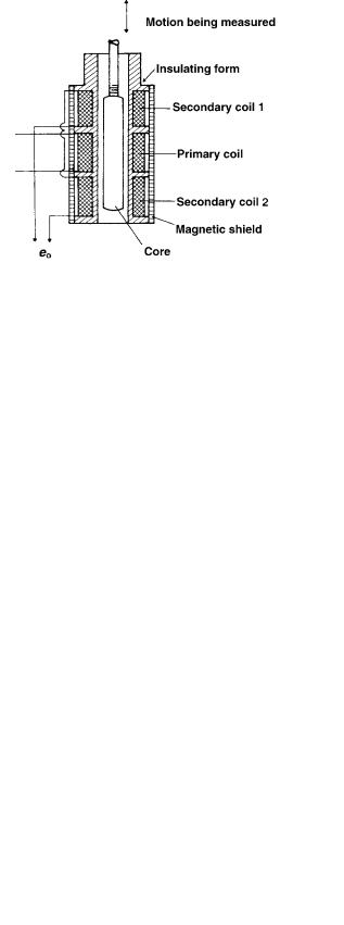
An LVDT is an inductive electromechanical transducer that uses a primary (energizing) coil and two seriesopposed secondary coils. This mode of connecting the secondaries serves to mutually cancel out the secondary voltages. In this popular configuration, due to Shaevitz (1), the primary winding is symmetrically placed with respect to the secondary windings on a cylindrical former. The former surrounds a free-moving rod-shaped magnetic core, which provides a path for the magnetic flux linking the coils (Fig. 1). The magnetic core is connected to a sensing device like a movable diaphragm. Movement of the sensor induces core movement, which in turn produces voltage variations that are measured directly.
When the sliding magnetic core is in the central (null) position, the electromotive forces (emfs) generated in the secondaries are equal, and the net output voltage, e0 is, therefore, zero. Movement of the core from this central position causes the mutual inductance (coupling) for one coil to increase and the other coil to decrease. The amplitude of the output voltage, e0, being the difference between the emfs in the two secondaries, varies approximately linearly with the position of the core on either side of the null position (Fig. 2). The differential secondary con-
Figure 1. Schematic of the cutaway view of an LVDT showing the core, primary coil, and two secondary coils: (ei) excitation voltage; (e0) output voltage.
nection in the LVDT causes the phase of the output voltage to change by 1808 as the core passes through the null position. The output voltage, e0, is generally out of phase with the excitation voltage, ei. The phase shift is dependent on the frequency of ei, and each LVDT has a particular frequency at which phase shift is zero.
FABRICATION
The LVDT features essentially frictionless measurement and long mechanical life, because there is no mechanical
Figure 2. Output voltage of an LVDT as a linear function of core position.
contact between the enclosed coil assembly and the separate freely moving core within the coil assembly (Fig. 1).
A typical alternating current (ac) LVDT core consists of a uniformly dense cylindrical slug of a high permeability nickel–iron alloy. The core is internally threaded to accept nonmagnetic core rods from an external sensing or actuating element. The core moves within a cylindrical coil assembly. Hollow cores are employed when a low mass core is desired. Recently, researchers have developed lightweight glass-covered amorphous wire cores that can be used to fabricate high sensitivity LVDTs with good mechanical and corrosion resistance (2). The primary and secondary windings are spaced symmetrically by winding them on a slotted cylindrical former. To avoid material corrosion or insulation leakage, the windings are impregnated with an insulating varnish under a vacuum. The coils are encapsulated in epoxy for further mechanical and moisture protection. Magnetic or ferromagnetic materials in the proximity of an LVDT can disrupt its magnetic field. The magnetic field of an LVDT may also induce eddy currents into nonmagnetic materials in its vicinity. These currents in turn would create a magnetic flux that would interfere with the LVDT output. These problems are avoided in practice by enclosing the LVDT in a case fabricated from an alloy, a high permeability iron, or a stainless steel. The LVDT assembly is then mounted in a C- or split block. LVDTs that can measure rotational movement are also available.
In addition to the ac LVDTs described in the previous sections, direct current (dc) LVDTs are also available (3,4). These LVDTs, in addition to having all the advantages of ac LVDTs, possess the simplicity of dc operation. They consist of two integral parts: an ac-operated LVDT and a carrier generator–signal conditioning module. The small carrier system eliminates the need for the ac excitation, demodulation, and amplification equipment required for conventional ac LVDTs. This cuts down the cost and reduces the volume of LVDT instrumentation; dc units can be battery operated or be supplied by a simple dc power supply (3,4). Also, any dc meter can be employed to read the LVDT output. These advantages, coupled with the small size of the dc LVDTs, make them attractive for use in hospitals and other medical environments.
The LVDTs have several advantages and a few disadvantages (3–6) as briefly reviewed next.
1.Essentially frictionless operation and long mechanical life: As described in the previous section, the LVDT has no moving mechanical contact between the moving core and the windings. This ensures that LVDTs have a fast dynamic response as no additional load apart from the core mass is imposed on the measured event. In addition, this helps LVDTs to have a long, essentially infinite, mechanical life.
2.Good in hostile environments: LVDTs can be manufactured to withstand the vagaries of chemical corrosion and extremes of temperature and pressure. This is facilitated by the separation between the core and windings of the LVDT. Only a static seal is required to isolate the coil assembly from hostile environments.
LINEAR VARIABLE DIFFERENTIAL TRANSFORMERS |
253 |
3.Extremely high resolution: LVDTs can respond to extremely small displacements. Microdisplacement LVDT transducers capable of measuring displacements down to 100 pm have been fabricated (7).
4.Null repeatability: The null position of an LVDT is very repeatable, even with large temperature variations.
5.Input–Output isolation: Since the primary and secondary windings are isolated from each other, the signal ground can be isolated from the excitation ground.
6.Cross-axis rejection: The LVDT is only responsive to axial core motion. Cross-axis motion induced by conditions such as jarring or continuous vibration will not affect the LVDT output.
7.Overtravel damage resistance: As the LVDT core can pass completely through the coil assembly, the transducer is inherently immune to damage from unanticipated overtravel that can be encountered in applications where materials or structures can yield or fail.
8.Absolute output: Unlike a lot of other transducers that are incremental output devices, LVDTs are absolute output devices, that is, the displacement information from an LVDT is not lost if the system loses power. When the measuring system is restarted, the LVDTs output value will be the same as it was before the power failure occurred.
All these advantages, in addition to their reasonable cost, have made the LVDT an attractive displacement measurement technique. However, LVDTs for use in medical applications have the following disadvantages: (1) They require a constant amplitude excitation of high frequency. (2) They cannot be used in the vicinity of equipment that creates strong magnetic fields.
LVDT INSTRUMENTATION
Instrumentation normally used with an ac LVDT should perform the following functions (3,4).
Excitation
An LVDT needs an ac input of constant amplitude at a frequency that is not readily available. Hence, an oscillator of the appropriate frequency has to be connected to an amplifier with amplitude regulation on its output.
Amplification
As in the case of most transducers, the low level outputs of LVDTs require amplification. One procedure for amplification employs two steps: (1) use of an ac carrier–amplifier before demodulation; and (2) a dc amplifier after the demodulator (3,4).
Demodulation
As discussed earlier, the output of an LVDT remains proportional to the displacement while it undergoes a
254 LINEAR VARIABLE DIFFERENTIAL TRANSFORMERS
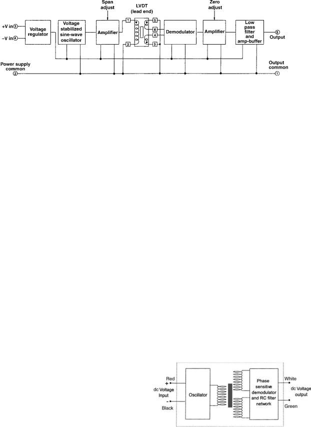
Figure 3. Block diagram for an LVDT employing a series 1000 oscillator–demodulator supplied by Trans-Tek, Inc. (Courtesy of Trans-Tek Inc.)
phase shift of 1808 when the core goes through the null. When this LVDT output is connected to a voltmeter, the meter will register the same reading for equal amounts of core displacement on either side of the null position. This lack of directional sensitivity has to be overcome if one has to tell to which side of the null the core is displaced. Two techniques can be used to confer directional sensitivity on an LVDT output. In one technique, the core is offset, and the operation is centered on a position other than the null point. In this case, the output signal either increases or decreases. The other procedure uses a phase-sensitive demodulator (also called a detector). Several such devices are available and are discussed in detail elsewhere (8). The simplest forms employ diode rectification while the complex forms involve synchronous demodulation. Figure 3 shows the block diagram for an LVDT employing a series 1000 oscillator–demodulator supplied by Trans-Tek, Inc. (9).
The demodulator confers directional sensitivity on its input (output of the LVDT), which is either in phase with, or 1808 out of phase with, the carrier signal (10). The demodulator output e0 is usually sent to a low pass filter that will pass only the frequencies present in x and reject all higher frequencies created by the modulation procedure. Obviously, demodulation is not required if the LVDT transducer is to be used only on one side of the null position.
Recent developments allow all LVDT support circuitry to be accomplished using an inexpensive flexible field programmable analog array (FPAA). The FPAA consists of ‘‘configurable analog blocks’’ consisting of switched-capa- citor op-amp cells surrounded by a programmable interconnect and I/O structure (11).
dc Power
Stable dc voltage sources are required for operation of the electronics associated with LVDTs. The dc LVDTs available at the present time employ a microcircuit module including all the electronics needed to provide ac excitation to the primary of the LVDT and to demodulate and amplify the analog LVDT signal. The module is mounted in tandem with the LVDT and only increases the effective LVDT length slightly.
Figure 4 shows the block diagram for a dc LVDT (9). The oscillator produces a constant amplitude sine wave excitation for the primary of the LVDT. A phase sensitive demodulator and an RC filter network process the secondary coil output. Some dc LVDT modules are furnished with
a reverse polarity protector for the dc power input. dc LVDTs are becoming increasingly popular due to their advantages in the areas of calibration and signal conditioning.
SELECTION CRITERIA
Several criteria have to be considered in selecting a particular LVDT for a certain application (12). The manufacturer supplies several of these parameters as specification criteria.
Total Stroke
Stroke-length specification in the selection of an LVDT for a particular application is governed by the displacement to be measured. LVDTs can be custom-made for either short- (up to 0.01 m) or long-stroke (up to 1.5 m) operation; however, cost of fabrication increases greatly with increase in length, and lengths over 0.03 m may not be cost effective.
Linearity and the Nominal Linear Range
The output of an LVDT is a nearly linear function of core position for a rather wide range on either side of the balance (null) position (Fig. 2). A nominal linear range is defined for an LVDT as the core displacement on either side of the balance position for which the LVDT output as a function of displacement remains a straight line. Outside this range, the output starts to deviate gradually from the ideal straight line in the form of a smooth curve. Linearity of an LVDT is defined as ‘‘the maximum deviation from a best-fit straight line (applied to a plot of LVDT output voltage vs. core displacement) within the nominal linear
Figure 4. Block diagram of a dc LVDT. (Courtesy of Trans-Tek Inc.)
range’’ (12). Linearity is usually expressed as a percentage of the full scale. A typical LVDT has a linearity of about0.25%.
Sensitivity
The sensitivity of an LVDT is usually expressed as the output in millivolts (or V) per 0.001 m core displacement per volt input. Normally, both the input voltage and the frequency are specified as well, because voltage sensitivity may vary with frequency over a limited frequency range. A typical miniature LVDT transducer has a sensitivity of8–200 mV out/0.001 m/V input.
Resolution
Resolution of an LVDT is the smallest core movement that can produce an observable change in the voltage output (12). With careful circuit design, displacements smaller than 100 nm can be detected.
Armature Mass
The mass of the armature (core) of the LVDT should be small so as not to unduly load the measured event. A reduction in the length of the LVDT results in a reduction in either the linearity or the maximum linear range, whereas sensitivity increases.
Excitation Frequency and Voltage
The sensitivity of the LVDT depends on both the excitation voltage and frequency. Normally, a sinusoidal voltage of 3–15 V rms amplitude and a frequency of 60 Hz–20 kHz is used for the excitation of LVDTs. The sensitivity of an LVDT increases with the excitation frequency, particularly at the lower part of the operating frequency range (12). Normally, an excitation frequency range of 1–5 kHz produces optimal LVDT operation.
Operating Environment
LVDTs have the advantage of being available in hostile- environment-proof format. Transducers designed to withstand both high and cryogenic temperatures and high pressures are available. Immersion-type LVDTs resistant to corrosive liquids are also available. Normally, specification criteria for an LVDT include information on the temperature range of operation and the temperature coefficient.
Residual Voltage Output
The residual voltage output is the LVDT output when the core is in the null position. This should ideally be zero; however, the null voltages and the harmonics of the excitation source do not cancel, resulting in a nonzero residual output (12). In practice, the residual voltage is about 1% of that obtained with maximum displacement.
Repeatability
Repeatability, the ability of the LVDTs to give the same output if the core is displaced and returned to the
LINEAR VARIABLE DIFFERENTIAL TRANSFORMERS |
255 |
original position is an important consideration. LVDTs with repeatability better than 100 nm are available for some critical applications.
MEDICAL APPLICATIONS
LVDTs are used in medical applications and research to measure physiological variables that are either available in the form of a linear displacement or can be converted into such movement. LVDTs for medical applications can be readily fabricated in very small sizes with low mass cores. This will ensure that only a negligible force is imposed on the measured physiological event. Also, due to the low alternating currents in the windings, negligible magnetic load is imposed. When not in use, the core remains in the null position, and no force is imposed on the measured event. Even when the core is displaced from null, the load imposed on the event is small. These advantages, coupled with the general advantages of LVDTs discussed in the previous paragraphs, make these transducers very attractive for physiological measurements.
One early application of LVDTs was in the fabrication of invasive blood pressure measurement transducers (13). These transducers consisted of three essential parts: (1) a dome with pressure fittings, (2) a stainless steel diaphragm and core assembly, and (3) the LVDT coils. Pressure transmitted via the catheter exerts a force on the diaphragm. This causes a movement of the diaphragm, which in turn manifests itself in a movement of the core attached to it. Movement of the core of the LVDT creates a proportional output that can then be recorded after suitable electronic circuit processing. Catheter tip and implantable transducers employed the same principle (13). However, these rugged LVDT blood pressure transducers have been supplanted by cost-effective microelectromechanical system (MEMS) type transducers (14).
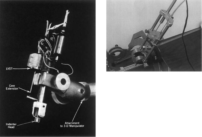
Another application for LVDT transducers is in indentation tests on tissue to determine mechanical properties. The authors have developed an LVDT indenter for the characterization of the mechanical properties of skin and the underlying soft tissue (Fig. 5). The indenter uses a loaded hemispherical tip coupled with a load cell-LVDT system for simultaneously measuring both the force and displacement during indentation tests. This information in turn was used to evaluate soft tissue properties. Walsh and Schettini (15) used a similar indenter to measure the in vivo viscoelastic response properties of brain tissue. Oculotonometers operating on the same principle and designed to indent the corneoscleral shell use LVDTs to measure deflections in the micrometer range (16). In another similar application, Gunner et al. (17) used an LVDT transducer-mounted extensometer to measure the in vivo recoil characteristics of human skin. The device consisted of two flat rectangular tabs, one fixed and the other capable of rectilinear sliding motion, attached to the test skin surface with double-sided adhesive tape. This combination was attached to an LVDT displacement transducer. Behavior of the skin resulting from the movement of the tabs was converted by the LVDT into electronic signals that were then analyzed to characterize the skin.
256 LINEAR VARIABLE DIFFERENTIAL TRANSFORMERS
Figure 5. An LVDT skin and tissue indenter. (Courtesy of N. P. Reddy, J. Kagan and G. V. B. Cochran.)
Christiansen et al. (18) used a similar device for the viscoelastic characterization of skin. These examples are just a few of the myriad potential applications for LVDT transducers in soft tissue characterization.
Several radiological and neurological devices have incorporated LVDTs. For example, Laser Diagnostic Technologies of San Diego, CA, incorporated a positionsensing DC-DC LVDT into a scanning laser tomography instrument designed for retinal topography (9). The stable and repeatable DCDT output is part of a continuous feedback loop in the scanner’s on-board logic control system. Radionics, Inc., employed an LVDT in a sophisticated modular probe drive used to support the precise implantation of deep brain stimulating electrodes (9). The device uses a push–pull cable drive mechanism to move the carrier that guides the probe to the desired location in the brain. The LVDT is mounted at the top of the mechanism and is used to accurately monitor probe position (Fig. 6). The LVDT used in this application was sealed to resist moisture and was modified to withstand the rigors of steam sterilization.
LVDTs have been used in endocrinology and pharmacology to evaluate in vitro and in vivo contractile properties of vascular smooth muscle. Erdos et al. (19) designed an
Figure 6. Mechanism of modular brain probe drive showing the LVDT used to help in precise electrode placement. [Courtesy of Radionics (a division of Tyco Healthcare).]
in vitro isotonic myograph employing an LVDT. The device resembled a beam-type balance. One arm of the device was connected to the contracting muscle specimen, and the other arm was counterbalanced by a suspended weight. Motion of the weight was translated via the movement of an LVDT core into electronic signals.
Gow (20) employed a novel LVDT electronic caliper for the continuous monitoring of arterial diameter changes during pulsation. This low mass device was found to possess a rapid response time with a natural resonant frequency greater than 180 Hz. Shykoff et al. (21) used LVDT measurements of changes in diameter of dorsal hand veins to establish diameter, pressure, and compliance relationships. LVDT-based devices have been used to evaluate the in vivo vascular effects of drugs with the dorsal hand vein technique (22). For example, Landau et al. (23) used an LVDT-based device to evaluate the mag- nesium-induced vasodilation in the dorsal hand vein. A similar technique was used by Streeten and Anderson (24) to measure venous contractile responses to locally infused norepinephrine.
LVDTs have been used in numerous orthopedic and dental devices. Chen et al. (25) used an LVDT bonded to the mandibular first molars to quantify mandibular deformation during mouth opening. Other possible medical applications are the mapping of facial contours before and after maxillofacial surgery and the profiling of spinal deformation in abnormalities like scoliosis. Buhler et al. (26) and Flamme et al. (27) used LVDTs to quantify micromotion in orthopedic implants. Recently, Dong et al.(28) incorporated an LVDT into a device for quantitative assessment of tension in wires of fine-wire external orthopedic fixators.
An LVDT was used to calibrate finger movements and to correlate these movements with surface electromyograms from the flexor digitorum superficialis muscles in the forearm (29,30). This work was designed to develop techniques for control of anthropomorphic teleoperator fingers
using surface electromyographic signals obtained from the forearm.
Wang et al. (31) used six spring-loaded LVDTs in an experimental technique to measure three-dimensional (3D), six-degrees-of-freedom motion of human joints. Rotary LVDTs are useful for measuring joint angles. For measuring 3D rotations, rotary LVDTs are incorporated into six- degree-of-freedom motion linkages.
As illustrated in the applications discussed above, LVDTs are highly suited for biomedical device and research applications requiring accurate displacement measurements with high resolution, input–output isolation, and crossaxis rejection. Although LVDTs are being replaced by miniaturized, cost-effective transducers utilizing advanced fabrication technologies in many applications, their advantages still render them excellent candidates for biomedical applications.
ACKNOWLEDGMENT
The authors would like to acknowledge the help provided by Rema Menon in the preparation of this manuscript.
BIBLIOGRAPHY
1.Schaevitz H. The linear variable differential transformer. Proc Soc Stress Anal 1947;4:79–88.
2.Chiriac H, Hristoforou E, Neagu M, Pieptanariu M. Linear variable differential transformer sensor using glass-covered amorphous wires as active core. J Magn Magn Mater 2000; 215:759–761.
3.Schaevitz Engineering. Technical bulletins 1002D and 7007. Pennsauken (NJ) 1986.
4.Schaevitz Sensors. Shaevitz Sensor Solutions. Catalog No. SCH-2001 Hampton (VA) 2000.
5.[Anonymous]. No date. An LVDT Primer. [Online]. Macro Sensors. Available at www.macrosensors.com. 2005 March 8.
6.Weinstein E. LVDTs on the factory floor. Instrum Control Syst 1982;55:59–61.
7.Sydenham PH. Microdisplacement transducers. J Phys E 1972;6:721–733.
8.Szczyrbak J, Schmidt EDD. LVDT signal conditioning techniques. Meas Control 1997;183:103–111.
9.[Anonymous]. No date. LVDT application. [Online]. TransTek Inc. Available at www.transtekinc.com. 2005 March 8.
10.Doebelin EO. Measurement Systems: Application and Design. 4th ed. New York: McGraw-Hill; 1990.
11.Severn J, October. 2001. New analog interface for LVDTs. [Online]. Industrial Technology. Available at www.industrialtechnology.co.uk. 2005 March 8.
12.Anonymous, Finding the right LVDT. Instrum Control Syst 1977;50:61–62.
13.[Anonymous]. No date. LVDT Applications. [Online]. Macro Sensors. Available at www.macrosensors.com. 2005 March 8.
14.Seeley RS. 1996. The future of medical microelectromechanical systems. [Online]. Available at www.devicelink.com/ mem/archive/96/01/003.html. 2005 March 8.
15.Walsh EK, Schettini A. A pressure-displacement transducer for measuring brain tissue properties in vivo. J Appl Physiol 1975;38:187–189.
16.Stepanik J. The Mackay-Marg Tonometer. Acta Ophthal 1970;48:1140.
LINEAR VARIABLE DIFFERENTIAL TRANSFORMERS |
257 |
17.Gunner CW, Hutton WC, Burlin TE. An apparatus for measuring the recoil characteristics of human skin in vivo. Med Biol Eng Comput 1979;17:142–144.
18.Christiansen MS, Hargens III CW, Nacht S, Gans EH. Viscoelastic properties of intact human skin: Instrumentation, hydration effects, and the contribution of the stratum corneum. J Invest Dermatol 1977;69:282–286.
19.Erdos EG, Jackman V, Barnes WC. Instrument for recording isotonic contractions of smooth muscles. J Appl Physiol 1962;17: 307–308.
20.Gow BS. An electrical caliper for measurement of pulsatile arterial diameter changes in vivo. J Appl Physiol 1966;21: 1122–1126.
21.Shykoff BE, Hawari FI, Izzo JL. Diameter, pressure and compliance relationships in dorsal hand veins. Vasc Med 2001;6(2):97–102.
22.Pang YC. Autonomic control of venous system in health and disease: effect of drugs. Pharmacol Therapeut 2001;90:179– 230.
23.Landau R, Scott JA, Smiley RM. Magnesium-induced vasodilation in the dorsal vein. BJOG (Bri J Obst Gyn) 2004;111: 446–451.
24.Streeten DHP, Anderson GH. Mechanisms of orthostatic hypotension and tachycardia in patients with pheochromocytoma. AJH 1996;9:760–769.
25.Chen DC, Lai YL, Chi LY, Lee SY. Contributing factors of mandibular deformation during mouth opening. J Dent 2000;28(8):583–588.
26.Buhler DW, Oxland TR, Nolte LP. Design and evaluation of a device for measuring three-dimensional motions of press-fit femoral stem prosthesis. Med Eng Phys 1999;19:187–199.
27.Flamme CH, Kohn D, Kirsch L, Hurschler C. Primary stability of different implants used in conjunction with high tibial osteomy. Arch Orth Trauma Surg 1999;119:450–455.
28.Dong Y, Saleh M, Yang L. Quantitative assessment of tension in wires of fine-wire external fixators. Med Eng Phys 2005;27:63–66.
29.Gupta V, Reddy NP. Surface electromyogram for the control of anthropometric teleoperator fingers. Weghorst SJ, Soeburg HB, Morgan KS, editors. Medicine Meets Virtual Reality: Healthcare in the Information Age. Amsterdam: IOP Press; 1996.
30.Devavaram A, Reddy NP. Intelligent systems for control of telemanipulators using surface EMG signals, submitted for publication.
31.Wang M, Bryant JT, Dumas GA. A new in vitro measurement technique for small three-dimensional joint motion and its application to the sacroiliac joint. Med Eng Phys 1996;18(6): 495–501.
Further Reading
Herceg ED. Handbook of Measurement and Control, Pennsauken (NJ): Schaevitz Engineering; 1972.
Anonymous. LVDTs remain ‘‘State-of-the-art. Meas Inspect Technol 1982;4(2):13–16.
Anonymous. Displacement transducers (linear variable differential transformer products review). Control Instrum 1984;16(8): 23–25.
Geddes LA, Baker LE. Principles of Applied Biomedical Instrumentation. 3rd ed. New York: Wiley-Interscience; 1989.
Webster JG. Medical Instrumentation: Application and Design. 3rd ed. New York: John Wiley & Sons; 1998.
See also BLOOD PRESSURE MEASUREMENT; INTEGRATED CIRCUIT TEMPERATURE SENSOR.