

- •VOLUME 4
- •CONTRIBUTOR LIST
- •PREFACE
- •LIST OF ARTICLES
- •ABBREVIATIONS AND ACRONYMS
- •CONVERSION FACTORS AND UNIT SYMBOLS
- •HYDROCEPHALUS, TOOLS FOR DIAGNOSIS AND TREATMENT OF
- •HYPERALIMENTATION.
- •HYPERBARIC MEDICINE
- •HYPERBARIC OXYGENATION
- •HYPERTENSION.
- •HYPERTHERMIA, INTERSTITIAL
- •HYPERTHERMIA, SYSTEMIC
- •HYPERTHERMIA, ULTRASONIC
- •HYPOTHERMIA.
- •IABP.
- •IMAGE INTENSIFIERS AND FLUOROSCOPY
- •IMAGING, CELLULAR.
- •IMAGING DEVICES
- •IMMUNOLOGICALLY SENSITIVE FIELD–EFFECT TRANSISTORS
- •IMMUNOTHERAPY
- •IMPEDANCE PLETHYSMOGRAPHY
- •IMPEDANCE SPECTROSCOPY
- •IMPLANT, COCHLEAR.
- •INCUBATORS, INFANTS
- •INFANT INCUBATORS.
- •INFUSION PUMPS.
- •INTEGRATED CIRCUIT TEMPERATURE SENSOR
- •INTERFERONS.
- •INTERSTITIAL HYPERTHERMIA.
- •INTRAAORTIC BALLOON PUMP
- •INTRACRANIAL PRESSURE MONITORING.
- •INTRAOCULAR LENSES.
- •INTRAOPERATIVE RADIOTHERAPY.
- •INTRAUTERINE DEVICES (IUDS).
- •INTRAUTERINE SURGICAL TECHNIQUES
- •ION-EXCHANGE CHROMATOGRAPHY.
- •IONIZING RADIATION, BIOLOGICAL EFFECTS OF
- •ION-PAIR CHROMATOGRAPHY.
- •ION–SENSITIVE FIELD-EFFECT TRANSISTORS
- •ISFET.
- •JOINTS, BIOMECHANICS OF
- •JOINT REPLACEMENT.
- •LAPARASCOPIC SURGERY.
- •LARYNGEAL PROSTHETIC DEVICES
- •LASER SURGERY.
- •LASERS, IN MEDICINE.
- •LENSES, CONTACT.
- •LENSES, INTRAOCULAR
- •LIFE SUPPORT.
- •LIGAMENT AND TENDON, PROPERTIES OF
- •LINEAR VARIABLE DIFFERENTIAL TRANSFORMERS
- •LITERATURE, MEDICAL PHYSICS.
- •LITHOTRIPSY
- •LIVER TRANSPLANTATION
- •LONG BONE FRACTURE.
- •LUNG MECHANICS.
- •LUNG PHYSIOLOGY.
- •LUNG SOUNDS
- •LVDT.
- •MAGNETIC RESONANCE IMAGING
- •MAGNETOCARDIOGRAPHY.
- •MANOMETRY, ANORECTAL.
- •MANOMETRY, ESOPHAGEAL.
- •MAMMOGRAPHY
- •MATERIALS, BIOCOMPATIBILITY OF.
- •MATERIALS, PHANTOM, IN RADIOLOGY.
- •MATERIALS, POLYMERIC.
- •MATERIALS, POROUS.
- •MEDICAL EDUCATION, COMPUTERS IN
- •MEDICAL ENGINEERING SOCIETIES AND ORGANIZATIONS
- •MEDICAL GAS ANALYZERS
- •MEDICAL PHOTOGRAPHY.
- •MEDICAL PHYSICS LITERATURE
- •MEDICAL RECORDS, COMPUTERS IN
- •MICROARRAYS
- •MICROBIAL DETECTION SYSTEMS
- •MICROBIOREACTORS
- •MICRODIALYSIS SAMPLING
- •MICROFLUIDICS
- •MICROPOWER FOR MEDICAL APPLICATIONS
- •MICROSCOPY AND SPECTROSCOPY, NEAR-FIELD
- •MICROSCOPY, CONFOCAL
- •MICROSCOPY, ELECTRON
- •MICROSCOPY, FLUORESCENCE
- •MICROSCOPY, SCANNING FORCE
- •MICROSCOPY, SCANNING TUNNELING
- •MICROSURGERY
- •MINIMALLY INVASIVE SURGICAL TECHNOLOGY
- •MOBILITY AIDS
- •MODELS, KINETIC.
- •MONITORING IN ANESTHESIA
- •MONITORING, AMBULATORY.
- •MONITORING, FETAL.
- •MONITORING, HEMODYNAMIC
- •MONITORING, INTRACRANIAL PRESSURE
- •MONITORING, NEONATAL.
- •MONITORING, UMBILICAL ARTERY AND VEIN
- •MONOCLONAL ANTIBODIES
- •MOSFET.
- •MUSCLE ELECTRICAL ACTIVITY.
- •MUSCLE TESTING, REHABILITATION AND.
- •MUSCULOSKELETAL DISABILITIES.
234 LENSES, INTRAOCULAR
is thus the most favorable condition. Different materials have been used for phonatory prostheses. For indwelling prostheses, silicone rubber is the material of choice, though other materials such as polyurethane have also been used. The most significant problem affecting voice prostheses is the formation of a thick biofilm on the esophageal surface, as the esophageal environmental around the prosthesis provides ideal growing conditions for bacteria, fungi, and yeast.
In this area, secretions from the trachea, the mucous membranes in the oropharynx and esophagus, and saliva from the oral cavity create an optimal ‘‘pabulum’’ for microorganisms, which can thus adhere to the prosthesis surface. Though biofilm does not lead immediately to valve, malfunction, colonies growing around the prosthesis can increase airflow resistance, blocking the valve or preventing it from closing correctly. This causes saliva to leak from the oral cavity through the esophagus lumen. The biofilm also grows into the valve material (silicone rubber).
Massive microorganism growth is more frequent in indwelling prostheses than in non-indwelling types, as the latter are regularly removed and cleaned.
The first step of this colonization is the formation of a very thin layer of organic origin, called a conditioning film. Microorganisms adhere to the thin layer of saliva conditioning film on the inner esophageal surface of the device and form the first stratum of biofilm, which is nearly impossible to eradicate. There are few methods for reducing the growth of bacteria and fungi: One possibility is to apply (through oral instillations) antimycotic drugs that reduce biofilm formation and increase prosthesis life (1,2,7,8,13,14). The valve has a limited life, varying from4 to 8 months. After this period, the valve must be removed and changed in an outpatient procedure because of a dysfunctional mechanism caused by the biofilm, which causes food and liquids to leak from the esophageal area to the trachea.
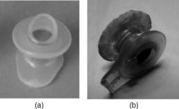
Figure 15 shows a new Provox valve (left) and a Provox valve after eight months of use by a patient (right). Silicon rubber deterioration caused by microbial action and adherent deposits of microorganisms is clearly apparent.
Current work with voice prostheses focuses on improving their aerodynamic characteristics (low airflow resistance) and developing more resistant materials that can extend the life of the device. For the patient, in any case, the most important thing after a total laryngectomy is to be hopeful: a prosthesis can provide a new voice, improving the quality of life.
Figure 15. Provox valve: (a) new and (b) old.
BIBLIOGRAPHY
1.Mahieu HF. Voice and speech rehabilitation following laryngectomy. Ph.D. dissertation, Rijksuniversiteit Groningen; 1988.
2.Pighi GP, Cristoferi V. Protesi tacheo-esofagee. Bologna: Arianna Editrice; 1998.
3.Societe´ Francaise d’Oto-Rhino-Laryngologie et de Pathologie cervico-faciale. Re´habilitation de la voix et de la de´glutition apre`s chirurgie du larynx. Arnette, Paris; 1992.
4.Testut L, Jacob O. Trattato di anatomia topografica. Vol. II Collo - Torace –Addome, Utet, Torino, 1998.
5.Harrison LB, Sessions RB, Hong WK. Head and neck cancer. Lippinocott Williams & Wilkins; 2004; 178–189.
6.http://www.orl.nl
7.Blom ED. Tracheoesophageal voice restoration: origin, evolution, state of the art. Folia Phonatrica Logopaedica 2000; 52:14–23.
8.Blom ED, Singer MI, Hamaker RC. Tracheoesophageal voice restoration following total laryngectomy. San Diego: Singular Publishing Group Inc.; 1998.
9.Brown DH, et al. Postlaryngectomy voice rehabilitation: state of the art at the millennium. World J Surg 2003;27(7):824–831.
10.Nakamura T, Shimizu Y. Thacheal, laryngeal and esophageal replacement device. The Biomedical Engineering Handbook CRC and IEEE Press; 2000, p 136/1–136/13.
11.Belforte G, Carello M, Miani C, Staffieri A. Staffieri tracheooesophageal prosthesis for voice rehabilitation after laryngectomy: an evaluation of characteristics. Med Biol Eng Comput 1998;36:754–760.
12.Staffieri M, Staffieri A. A new voice button for post-total laryngectomy speech rehabilitation. Laryngoscope 1988; 98(9):1027–1029.
13.Schwandt LQ, et al. Prevention of biofilm formation by dairy products and N-acetylcysteine on voice prostheses in an artificial throat. Acta Otolaryngol 2004;124:726–731.
14.Leunisse C, et al. Biofilm formation and design features of indwelling silicone rubber tracheoesophageal voice pros- theses—An electron microscopical study. J Biomed Mater Res 2001;58(5):556–563.
See also COMMUNICATION DEVICES; PULMONARY PHYSIOLOGY.
LASER SURGERY. See ELECTROSURGICAL UNIT (ESU).
LASERS, IN MEDICINE. See FIBER OPTICS IN MEDICINE.
LENSES, CONTACT. See CONTACT LENSES.
LENSES, INTRAOCULAR
HABIB HAMAM
Universite´ de Moncton
Moncton, New Brunswick,
Canada
INTRODUCTION
Ridley’s implantation (1949) of the first intraocular lens (IOL) marked the beginning of a major change in the practice of ophthalmology. The IOLs are microlenses placed inside the human eye to correct cataracts, nearsightedness, farsightedness, astigmatism, or presbyopia. There are two types of IOLs: anterior chamber lenses,
which are placed in the anterior chamber of the eye between the iris and the cornea, and posterior chamber IOLs, which are placed in the posterior chamber behind the iris and rest against the capsular bag. Procedures for implanting the IOLs and technologies for manufacturing them in various sizes, thicknesses, and forms as well as with various materials progressed tremendously in the last decade. Multifocal IOLs are one of the important signs of this progress. While monofocal IOLs, the most commonly used, are designed to provide clear vision at one focal distance, the design of multiple optic (multifocal) IOLs aims to allow good vision at a range of distances.
INTRAOCULAR LENSES: WHAT AND WHY?
An intraocular lens, commonly called IOL, is a tiny artificial lens implanted in the eye. It usually replaces the faulty (cataractous) cristalline lens. The most common defect of the natural lens is the cataract, when this optical element becomes clouded over. Prior to the development of IOLs, cataract patients were forced to wear thick coke bottle glasses or contact lenses after the surgery. They were essentially blind without their glasses. In addition to IOLs replacing the crystalline lenses, a new family of IOLs, generally referred to as phakic lenses, is nowadays subject of active research and development. (Phakos is the Greek word for lens. Phakic is the medical term for individuals who have a natural crystalline lens. In Phakic IOL surgery, an intraocular lens is inserted into the eye without removal of the natural crystalline lens.) These IOLs are placed in the eye without removing the natural lens, as is completed in cataract surgery. They are used to correct high levels of nearsightedness (myopia) or farsightedness (hyperopia).
An IOL usually consists of a plastic lens with plastic side struts called haptics to hold the lens in place within the capsular bag. The insertion of the IOL can be done under local anesthesia with the patient awake throughout the operation, which usually takes <30 min in the hands of an experienced ophthalmologic surgeon (Fig. 1).
HISTORICAL OVERVIEW
The idea of the IOL dates back to the beginning of modern cataract surgery when Barraquer developed keratomileusis (1). However, the first implantation of an artificial lens in the eye was probably attempted in 1795 (2). References to the idea of the IOL before World War II in ophthalmic literature are rare. There has been mention of limited animal experiments using both quartz and plastic material performed in the 1940s, but nothing had come of these efforts (3).
The most important step toward the implantation of IOLs came as a result of World War II pilots, and the injuries sustained when bullets would strike the plastic canopy of their aircraft (Fig. 2), causing small shards of plastic to go into their eye. In the late 1940s, Howard Ridley was an RAF ophthalmologist looking after these unfortunate pilots and observed, to his amazement, little or no reaction in cases in which the material had come from
LENSES, INTRAOCULAR |
235 |
Figure 1. Implantation of an IOL: Since the natural lens is left undistrubed, the operation ismuch simpler thana cataractoperation. The entire procedure consists of making a small incision at the edge of the cornea and placing the appropriate tiny plastic lens in the space between the iris and the cornea, (the anterior chamber). Stitches are used to close the incision.
Spitfire planes. He then concluded the poly(methyl methacrylate) (PMMA) material of the canopies (windshield) was compatible with eye tissue (4). This observation sparked the idea for inserting an artificial lens in the eye. Ridley, who was convinced this lens should be placed in the posterior chamber, designed a disk-shaped lens, much like the natural lens, with a small peripheral flange allowing him to hold the lens with forceps (4). The artificial lens, made entirely of PMMA, weighed slightly > 100 mg in air and was 8.35 mm in diameter. In several cases, he attempted to implant the lens following intracapsular surgery using the vitreous base for support (5). On November 29, 1949, the first successful IOL implantation was performed at St. Thomas Hospital in London (6,7). While far from perfect, the procedure worked well enough to encourage
Figure 2. Invention of the IOL: During World War II, Fighter pilots were sometimes involved in accidents where the plastic windshield (canopy) of their aircraft was shattered. Doctors found that fragments of the canopy that entered the eye were tolerated by the eye tissues. They might remain inside the eye for years, and the eye would not react.

236 LENSES, INTRAOCULAR
further refinement. Then, over a decade, Ridley implanted several hundred IOLs (8).
Though Ridley was ahead of his time, his method was subject to serious criticism. Complications were common and failure rates > 50% were often contemporaneously quoted. Fixation was dependent on the formation of adhesions between the iris and the capsule. Several ophthalmologists strongly opposed to his procedure. Implantation in the anterior chamber was technically easier and was compatible with intracapsular surgery. Also, fixation could be achieved at the time of implantation by adding haptic struts to the lens that could be wedged into the angle. The first anterior chamber lens was implanted by Baron in 1952
(8).
To make intraocular lens implantation safe, developments in lens design and surgical techniques were required. Lens implantation did not become widely adopted as an integral part of cataract surgery until the 1980s. Key advances were the introduction of viscoelastic fluids to protect the cornea during implantation and flexible haptics to enhance long term stability of the IOL (9).
With traditional single vision monofocal IOLs, people generally experience good vision after surgery at a single focal point, either near or at a distance. The multifocal IOL (10) was designed in the mid-1990s to provide a full range of vision with independence from glasses in most situations.
Besides, the invention of phakic lenses is no less important than Ridley’s invention. These IOLs were introduced by Strampelli (11) and later popularized by Barraquer in the late 1950s (12). Phakic IOLs are becoming more popular because of their good refractive and visual results and because they are easy to implant in most cases (13). In the beginning, the design was a biconcave angle-supported lens. These lenses were abandoned following serious angleand endothelium-related complications. By the late 1980s, Baikoff (14,15) introduced a myopia lens with Kelman-type haptics (16). This design had many problems, leading to its design modification a number of times. Fyodorov, the inventor of radial keratotomy (17), introduced the concept of a soft phakic lens in the space between the iris and the anterior surface of the crystalline lens (18).
Based on earlier works of Worst, winner of the Binkhorst Award for innovation in ophthalmology in 1976, Fechner introduced phakic myopia lens of iris claw design in 1986 (19). This IOL is then referred to as Worst–Fechner lens (20). Many companies around the world manufactured it in various models. Today, people usually identify it by the name of Artisan IOL.
MATERIAL OF THE IOL
Many factors, such as the optical quality of the system of the eye (aberrations, . . .), presence of inflammation, cost, and wound size, depend on the material and the form of the IOL.
From the point of view of flexibility, there are two families of IOLs: foldable and inflexible lenses. Foldable IOLs are generally made of acrylic or silicone. They can be rolled up and inserted through a tube with a very small incision not requiring any stitches. Inflexible IOLs, typically made of PMMA, require a larger incision because they are unfoldable. Most lenses are biconvex, thus optically equivalent upside down. However, most lenses have haptics which are generally angled to push the posterior optics.
Four basic materials are used for IOLs: PMMA, silicone, acrylic and collamer. Other materials are also used. For example, some manufacturers replace silicon by a hydrophilic biocompatible polymer, called collamer. Many IOLs have been made from PMMA plastic, the same plastic the original hard contact lenses were made of. Silicon IOLs are foldable. Folding an IOL allows it to be inserted through a smaller incision. A smaller incision heals faster and induces less postop astigmatism. Some foldable lenses are now being made of acrylic plastic. While acrylic and silicone lenses are very popular, PMMA is the time-tested material but, as stated above, requires a large incision. Silicone oil is also a problem for silicone IOLs in that the view of the fundus can be severely degraded. This is less so for PMMA and hydrophobic acrylic IOLs and least for hydrophilic acrylic. Although this is a relative contraindication for silicone IOLs in the face of significant vitreoretinopathy, a solvent exists that eliminates the problem (21). Collamer is a new hydrophilic material just recently released that has shown some interesting properties. It has been shown to exhibit less internal reflectance than other lens materials including silicone, acrylic, and PMMA (22). It reduces the risk of long-term inflammation (23). Table 1 summarizes the characteristics of the four materials.
VARIOUS PARAMETERS FOR IOLs
Are age, race, and sex important parameters for IOL implantation? Age at which surgery is performed turned out to be of great importance (24–28). The ideal age should be at around 18 years when the refraction stabilizes. However, in specific circumstances, in the interest of the minor patient, the parents and the surgeon can opt to perform phakic lens implantation at an earlier age. Studies
Table 1. Four Commonly Used IOLs Materials and their Advantages and Drawbacks
Material |
Flexibility |
Advantages |
Drawbacks |
|
|
|
|
PMMA |
Rigid |
Low cost, less inflammation, long-term experience, |
larger incision, not foldable |
|
|
good bicompatibility |
|
Silicone |
Foldable |
Smaller incision, injectable |
high cost, more inflammation, |
|
|
|
cannot use with silicon oil |
Collamer |
Foldable |
Smaller incision, less inflammation, very good bicompatibility |
high cost, short term experience |
Acrylic |
Foldable |
Smaller incision, less inflammation, high refraction |
high cost |
|
|
index (thin IOL), good bicompatibility |
|
|
|
|
|
of the suitable age of IOL implantation in children have been carried out (24). A 3-year-old child has been qualified with IOL implantation, the child younger than 9 years old should be implanted with a normal adult IOL and then corrected with glasses, and a child after 10 years old should be directly implanted with a proper dioptric IOL (24). Some researchers evaluated the influence of cataract surgery on the eyes of children between 1 and 5 years old. They concluded that cataract surgery, either extraction with or without IOL implantation, did not retard axial elongation in children above 1 year old (25). Comparisons between children with congenital or developmental lens opacities who underwent extracapsular cataract extraction and children with normal eyes have been carried out (26). The pattern of axial elongation and corneal flattening was similar in the congenital and developmental groups to that observed in normal eyes. No significant retardation or acceleration of axial growth was found in the eyes implanted with IOLs compared with normal eyes. A myopic shift was seen particularly in eyes operated on at 4–8 weeks of age and it is recommended that these eyes are made 6 D hyperopic initially with the residual refractive error being corrected with spectacles (26).
To our knowledge, IOL implantation does not depend on race and sex.
OPTICAL QUALITY
Two optical qualities are distinguinshed: the intrinsic optical quality of the IOL and the optical quality of the system of the eye including the IOL. Many factors, such as the material and the geometrical profile of the IOL, influence the intrinsic quality of this optical element. Axial shift (decentration), transversal rotation (not around the optical axis), and deformation (mechanical stresses, . . .) of the IOL are examples of factors affecting the optical quality of the whole system of the eye even in case the IOL alone is a perfect optical element. Thus, the optical quality of the IOL is certainly important. However, for vision, the determinant factor is the optical quality of the whole system of the eye in which the IOL is implanted. Several studies have been undertaken to assess the optical quality of the IOL and the optical quality of the whole system of the eye. Before progressing in this section, let us briefly introduce the notion of optical quality.
Aberrations
Stated in wave optics, the system of the eye should transform the input wavefront into a perfect convergent spherical wavefront that has the image point as center (29–31). Note that an optical wavefront represents a continuous surface composed of points of equal phase. Thus all imageforming rays, which travel normal to the exit spherical wavefront, meet in the focal point in phase, resulting in maximum radiant energy being delivered to that point. In reality, this situation never occurs. The rays modified by the optical system do not converge entirely to a common point image. For one object point correspond several image points that form a blurred image. This deviation from the ideal case is called optical aberration, or merely aberration,
LENSES, INTRAOCULAR |
237 |
and is a measure of the optical quality of the system. Aberration can be quantified either with respect to the expected image point or to the wavefront corresponding to this ideal point. If the real output wavefront is compared to the ideal one, it is called the difference between them wavefront aberration (29). All human eyes suffer from optical aberrations that limit the quality of the retinal image (32–36). Several metrics have been proposed to measure the optical quality of the system of the eye (37–41). Let us return back to IOLs now. Optical quality of multifocal IOLs will be treated in the section devoted to this kind of lens.
Optical Quality of the IOL
The optical quality of IOL was the subject of intensive studies. Several common but some contrasted results have been obtained. An exhaustive study goes beyond the scope of this document. We limit our attention to some recent results. Tognetto et al. (42) evaluated the optical quality of different IOLs by using an optical test bench. The purpose of the study was to evaluate the optical quality of IOLs and not to evaluate the optical performance of these lenses once implanted. Three randomly acquired samples of 24 different models of foldableIOLswerecompared.Theconclusionisthatdifferent IOLs can transmit different spectra of spatial frequencies. The best frequency response was provided by acrylic IOLs, particularly those with an asymmetrically biconvex profile. This could be due to a reduction of optical degradation providedbythis typeof profile. A lenswithahigher frequency response should create a better quality of vision once implanted, and the frequency response should therefore be considered when choosing the intraocular lens model (42).
Negishi et al. (43) evaluated the effect of chromatic aberrations in pseudophakic eyes with various types of IOLs. Their results show that longitudinal chromatic aberrations of some IOLs may degrade the quality of the retinal image. They concluded that attention must be paid to the detailed optical performance of IOL materials to achieve good visual function.
In a comparative study (44), Martin found that the collamer IOL reduced the number of induced higher order aberrations when compared with acrylic and silicone lenses. Indeed, he found that the collamer IOL has 55–117% fewer induced higher order aberrations than acrylic or silicone materials. As a consequence, it produces less postop glare. He concluded the collamer lens provides clearer vision than the other lenses.
Optical Quality of ARTISAN Lenses
Brunette et al. (45) evaluated the optical quality of the eye before and after the insertion of an ARTISAN phakic intraocular lens for the treatment of high myopia (range20.50 to 9.75D). Consecutive patients implanted with the ARTISAN lens by a single surgeon were prospectively enrolled. One eye per subject was tested. The wavefront aberration was calculated from images recorded with a Hartmann-Shack sensor (46,47). The PSF and the MTF were also computed from the wavefront aberration. It was concluded that preliminary data using the Hartmann– Shack wavefront sensor have not revealed a tendency
238 LENSES, INTRAOCULAR
toward deterioration of the optical performance following the insertion of an ARTISAN lens for the treatment of high myopia. The Hartmann–Shack sensor is a useful tool for the objective assessment of the image optical quality of eyes with a phakic intraocular lens.
MULTIFOCAL IOLs
Unlike the natural lens, the curvature of current intraocular lenses cannot be changed by the eye. Standard intraocular lenses provide good distance vision, and the patient needs reading glasses for near vision. Newer bifocal intraocular lenses give distance vision in one area and near vision in another area of the vision field. How does it work?
The basic idea consists in providing a lens with two posterior focal points instead of one. The IOL is no longer monofocal. It becomes bifocal. Two solutions are possible: refractive or diffractive bifocal lens. A third solution consists in combining both approachs together.
Diffractive Lenses
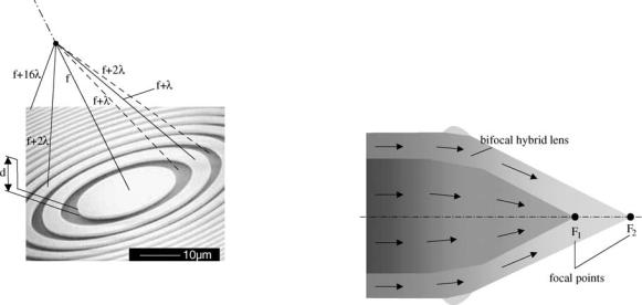
The idea comes from the principle of the Fresnel zone plate. It consists in designing a binary diffractive phase element so when the incident wave comes across this diffractive element, all the resulting waves, coming from all points of the zone plate, arrive in phase at a certain (focal) point. They then superimpose constructively, yielding a focusing behavior. As shown in Fig. 3, waves traveling along various segments arrive in phase at the focal point since the optical paths differ by a multiple of the wavelength. To fulfill this condition, the thickness d is chosen so that it introduces a phase shift of p: d ¼ ð2k þ 1Þ l=½2ðn 1Þ& (optical path: ð2k þ 1Þ l=2). In Fig. 3, k ¼ 0, yielding d ¼ l=½2ðn 1Þ&, where n is the refraction index of the diffractive lens. The radii of the rings (Fig. 3) verify the following rule:
circle |
|
r1 |
|
|
rm ¼ pm |
¼ pml f |
, where r1 is the radius of the smallest |
||
|
and f |
is the focal length. Without grooves on the |
||
diffractive, the waves traveling along the segments, represented by dashed lines in Fig. 3, would arrive in phase opposition with respect to other waves. In reality, the binary form (two phase levels) of the diffractive lens does not fully ensure the condition of coming in phase at the focal point. For rigor, several phase levels are required (Fig. 4). In general, the diffraction efficiency h, which is defined as the ratio of the focused energy to the incident energy, increases with the number of phase levels L according to the following formula (48): h ¼ sin2ðp=LÞ=ðp=LÞ2. Using two phase levels (binary), only 41% of the energy is focused. The rest is scattered in space. A four level diffractive lens focuses 81% of the input energy (it scatters only 19% of the incident energy).
To obtain a bifocal diffractive lens, we need to focus rays on two focal points at distances f1 and f2. It can be done by
providing two series of zones (rings). The first series, the |
|||
m ¼ 1,2,. . ., M), whereas the radii in |
2 |
|
|
inner one, involves radii verifying |
rmð1Þ |
¼ pml f1 |
(with |
|
the second series, |
||
p ¼ Mþ1,. . ., P). To obtain a multifocal |
|
|
|
the outer one, satisfy the condition |
rðp Þ |
¼ p pl f2 |
(with |
|
|
diffractive |
lens, |
we need more series of radii. |
|
|
|
Refractive Lenses
An alternative to obtain a multifocal length consists in modifying the surface profil of a conventional biconvex lens so that it provides two or more different focal points for light convergence. The technique consists in designing a spherical refractive surface that has additional refracting surfaces to give a near add (Fig. 5), or a near and intermediate add. The principle of multifocal refractive lenses is illustrated in Fig. 6a. Refractive IOLs with several focal points are commercialized in various models. For example, one of the models includes five refractive zones targeting distance, intermediate and near vision (Fig. 6b). The IOL uses continuous aspheric optics to ensure that 100% of the light entering the eye reaches the retina. The lens uses five concentric zones with the first, third, and fifth zones being far dominant and second and fourth zones being near dominant (49). The light distribution is arranged so that 50% of light is distant focussed, 13% is focussed for intermediate vision and 37% for near vision. The near add
Figure 3. Binary diffractive phase element: Fresnel zone plate. Waves traveling along various segments arrive in phase at the focal point since the optical paths differ by a multiple of the wavelength. To fulfill this condition, the thickness d is chosen so that it introduces a phase shift of p: d ¼ (2k + 1) l/[2(n 1)] (optical path: (2k + 1) l/2): In the figure, k ¼ 0.
Figure 4. Bifocal hybrid refractive/diffractive IOL: Anterior surface broken up into a refractive zone and a second zone composed of concentric diffractive rings.
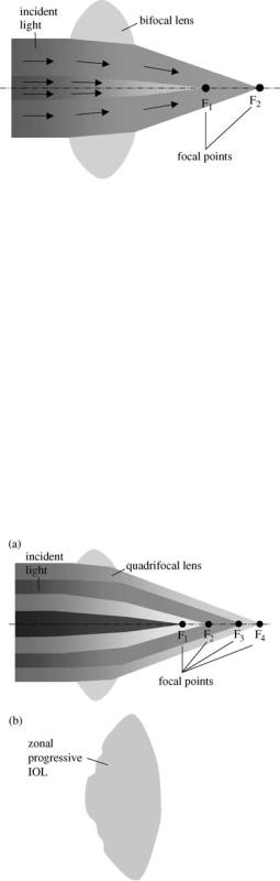
Figure 5. Bifocal refractive IOL: Spherical refractive surface that has additional refracting surfaces to give a near add.
comprises of 3.5 dioptre intraocular power equivalent to a 2.75–2.85 add in the spectacle plane (49).
Optical Quality of Refractive and Diffractive Lenses
This discussion will be limited to some recent results. Pieh et al. (50) compared the optical properties of bifocal diffractive and multifocal refractive intraocular lenses. The IOLs were manufactured by different companies. A model eye with a pupil 4.5 mm in diameter was used to determine the point spread function (PSF) (30,51) of the distance focus and near focus of the IOLs to compare them with PSFs of foci of corresponding monofocal lenses. For interpreting the PSFs the through focus response, the modulation transfer function (MTF) (51), and the Strehl ratio (51) were evaluated. They concluded the modulation transfer functions
Figure 6. Multifocal refractive IOLs: (a) several refractive surfaces with different curvatures. Each one provides a focal point
(b) a commercial zonal progressive IOL with five concentric zones on the anterior surface. Each zone repeats the entire refractive sequence corresponding to distance, intermediate and near vision, resulting in wide-range vision.
LENSES, INTRAOCULAR |
239 |
reveal comparable properties for distance vision and a superiority of the bifocal diffractive lens over the refractive multifocal lens for near vision. This mean due to the fact that the incoming light is distributed over different zones in the refractive lenses.
Hybrid Lenses
Diffractive and refractive optics (Fig. 4) can be combined. In this type of lens, the basic spherical refractive surface is broken up into a refractive zone and a second zone composed of concentric diffractive rings. This combination of zones creates two different focal points for light convergence, one for near objects and one for distant objects. Hybrid IOLs are basically bifocal lenses (Fig. 4). The usual strategy has been to have a distance component with a near component targeting the usual near distance. However, multifocal hybrid lenses are possible.
IOLs AND ACCOMODATION
New research into accommodating intraocular lenses indicates that many patients who get these implants will enjoy good distance and near vision (52). The first hint that intraocular lens implants could accommodate came back in 1986, when Thornton used A-scan biometry to report on anterior movement of a three-piece loop IOL (53). He found that this forward movement allowed some patients to have good uncorrected distance and near vision simultaneously.
The mechanisms of presbyopia remain incompletely understood. A review of the variety of such mechanisms has been presented by Atchison (54). Accommodation in the youthful, phakic human eye is accomplished by contraction of the ciliary body and subsequent release in the resting tension of the zonular fibers by which the crystalline lens is suspended, resulting in increased lens curvature (55–57). The weight of current evidence seems to suggest that although some loss of ciliary body action might contribute to reduced accommodation (58), significant ciliary body function persists into advanced maturity, and that loss of lens and capsule elasticity in concert with changes in the geometry of zonular attachments are probably most culpable in producing the distress of presbyopia (59). If so, replacement of the crystalline lens with a lens that responds to ciliary body contraction should restore accommodative function (60). Attempts to replace the crystalline lens by refilling the capsular bag with appropriately deformable gels have been made (59,61,62). McLeod et al. aimed at designing an accommodating intraocular lens with extended accommodative range that can be adapted to current standard phacoemulsification and endocapsular implantation technique (60). They concluded that a dual optic foldable IOL design can increase the optical effect of a given displacement and suggests improvements for accommodating intraocular lenses.
BIBLIOGRAPHY
1.Barraquer JI. Keratomileusis for the correction of myopia. Arch Soc Amer Oftalmol Optom 1964;5:27–48.
240 LENSES, INTRAOCULAR
2.Ascher K. Prothetophakia two hundred years ago. Am J Ophthalmol 1965;59:445–446.
3.Nordlohne ME. The Intraocular Lens Development and Results with Special Reference to the Binkhorst Lens, 2nd ed. The Hague: Dr. W. Junk b.v.; 1975: p 14–17
4.Ridley H. Intraocular acrylic lenses—past, present and future. Trans Ophthal Soc UK 1964;84:5–14.
5.Kwitko ML, Kelman CD, editors. Intraocular lens implantation: The Beginnings: The History of Modern Cataract Surgery. The Hague: Kugler Publications; 1998: p 35–52.
6.Apple DJ, Sims J. Harold Ridley and the invention of the intraocular lens. Surv Ophthalmol 1996;40:279–292.
7.Rosen E. History in the making. J Cataract Refract Surg 1997;23:4–5.
8.Choyce P. Intraocular Lenses and Implants. London; H K Lewis & Co. Ltd; 1964.
9.Apple DJ et al. Complications of intraocular lenses: A historical and histopathological review. Surv Ophthalmol 1984;29: 1–54.
10.Javitt JC, et al. Outcomes of cataract extraction with multifocal intraocular lens implantation. Functional status and quality of life. Ophthalmology 1997;104:589–599.
11.Strampeli B. Sopportabilita` di lenti acrilichi in camera anteriore nella afachia e nei vizi di refrazione. Ann Oftalmol Clin Ocul 1954;80:75–82.
12.Barraquer J. Anterior chamber plastic lenses. Results and conclusions from five years experience. Trans Ophthalmol Soc UK 1959;79:393–424.
13.Neuhann T, et al. Phakic intraocular lenses, J Refract Surg 1998;14:272–279.
14.Baikoff G, Joly P. Correction chirurgicale de la myopie forte par un implant de chambre anterior dans l’oeil phake. Bull Soc Belge Ophthalmol 1989;233:109–125.
15.Baikoff G. Phakic anterior chamber intraocular lenses. Int Ophthalmol Clin 1991;31:75–86.
16.Rosen ES, Haining WM, Arnott EJ editors. Intraocular Lens Implantation. London, New York: Mosby; 1984.
17.Fyodorov SN, Durnev VV. Operation of dosaged dissection of corneal circular ligament in cases of myopia of mild degree. Ann Ophthalmol 1979;11:1885–1890.
18.Fyodorov SN, Zuev VK, Aznavayez VM. Intraokuliarnaia korrektsia miopii vysokoi stepeni zadnekamernmi otritsatelimi linzami. Oftalmochirugia 1991;3:57–58.
19.Fechner PU, Alpar J. Iris Claw Lens or Lobster Claw Lens of Worst; 1986.
20.Fechner P, Worst J. A New concave intraocular lens for the correction of myopia. Eur J Implant Refract Surg 1989;1:41–43.
21.Hoerauf H, Menz DH, Dresp J, Laqua H. Use of 044 as a solvent for silicone oil adhesions on intraocular lenses. J Cataract Refract Surg 1999;25:1392–1396.
22.Ossipov A. Comparison of internal reflectance patterns of Collamer, acrylic and silicone. 1997. Data on file, STAAR Surgical.
23.Davis EA. Study of post-cataract surgery inflammation with 3 different IOLs (Collamer, SI40NB, AR40). Summary of data found in all patients. Presented at OSN Meeting: New York: October 2003.
24.Jia S, Wang X, Wang E. A study of suitable age for intraocular lens implantation in children according to ocular anatomy and development, Zhonghua Yan Ke Za Zhi. 1996 Sept; 32(5): 336–338.
25.Zou Y, Chen M, Lin Z, Yang W, Li S. Effect of cataract surgery on ocular axial length elongation in young children. Yan Ke Xue Bao 1998;14(1) : 17–20.
26.Flitcroft DI, Knight-Nanan D, Bowell R, Lanigan B, O’Keefe M. Intraocular lenses in children: changes in axial length, corneal curvature, and refraction. Br J Ophthalmol 1999;83(3):265–269.
27.Kora Y, et al. Eye growth after cataract extraction and intraocular lens implantation inchildren. Ophthalmic Surg 1993;24(7): 467–475.
28.Pan Y, Tang P. Refraction shift after intraocular lens implantation in children. Zhonghua Yan Ke Za Zhi 2001;37(5):328–331.
29.Welford W. Aberrations of Optical Systems. Bristol: Adam Hilger; 1962.
30.Born M, Wolf E. The Diffraction Principles of Optics: Electromagnetic Theory of Propagation, Interference, and Diffraction of Light, 6th ed. New York: Pergamon Press; 1989.
31.Hamam H. Aberrations and their impact on image quality. Wavefront Analysis, Aberrometers & Corneal Topography, Agarwal’s edition, 2003.
32.Castejon-Mochon JF, Lopez-Gil N, Benito A, Artal P. Ocular wave-front aberration statistics in a normal young population. Vision Res 2002;42(13):1611–1617.
33.Howland HC, Howland B. A subjective method for the measurement of monochromatic aberrations of the eye. J Opt Soc Am 1977;67(11):1508–1518.
34.Porter J, Guirao A, Cox IG, Williams DR Monochromatic aberrations of the human eye in a large population. J Opt Soc Am A Opt Image Sci Vis 2001;18(8):1793–1803.
35.Paquin MP, Hamam H, Simonet P, Objective measurement of the optical aberrations for myopic eyes, Opt Vis Sci 2002;79: 285–291.
36.Thibos LN, Hong X, Bradley A, Cheng X. Statistical variation of aberration structure and image quality in a normal population of healthy eyes. J Opt Soc Am A 2002;19:2329–2348.
37.Franc¸on M Vision dans un instrument entache´ d’aberration sphe´rique. The`se, e´ditions de la Revue d’Optique, 1945.
38.Smith WJ Modern optical engineering, the design of optical
system. New York: Me Graw-Hill, 1990.
´´ ´
39.Marechal A. Etude des effets combines de la diffraction et des aberrations ge´ome´triques sur l’image d’un point lumineux. Revue d’Optique; 1947.
40.Hamam H, New metric for optical performance. Opt Vis Sci 2003;80:175–184.
41.Marsack JD, Thibos LN, Applegate RA Metrics of optical quality derived from wave aberrations predict visual performance. J Vis 2004;4(4):322–328.
42.Tognetto D, et al. Analysis of the optical quality of intraocular lenses. Inv. Ophthalmol & Vis Sci (IOVS) 2004;45/8:2682–2690.
43.Negishi K, Ohnuma K, Hirayama N, Noda T. Effect of chromatic aberration on contrast sensitivity in pseudophakic eyes. Arch Ophthalmol 2001;119:1154–1158.
44.Matin RG. Higher-Order Aberrations and Symptoms with Pseudophakia, Symposium on Cataract, IOL and Refractive Surgery, April 12–16, 2003 San Francisco, CA.
45.Brunette I, et al. Optical quality of the eye with the artisan phakic lens for the correction of high myopia. Optomol Vis Sci 2003 Feb; 80(2):167–174.
46.Liang J, Grimm B, Goelz S, Bille JF. Objective measurement of wave aberrations of the human eye with the use of a Hart- mann-Shack wave-front sensor. JOSA A 1994;11:1949–1957.
47.Hamam H. An apparatus for the objective measurement of ocular image quality in clinical conditions. Opt Commun 2000;173:23–36.
48.Hamam H, de Bougrenet JL. Efficiency of programmable quantized diffractive phase elements. Pure and Appl Opt 1996;5:389–403.
49.Wilson K. New Technology Removes Cataract and Improves Vision. Geriatr and Aging 1998;1: p 15.
50.Pieh S, et al. Quantitative performance of bifocal and multifocal intraocular lenses in a model eye: Point spread function in multifocal intraocular lenses. Arch-Ophthalmol. 2002;120(1): 23–28.
51.Malacara D, Malacara Z. Handbook of Lens Design. New York; Marcel Dekker 1994.
52.Karpecki PM. The future of IOLs that accommodate. Rev Opt Dec 2002.