

62 HYPERTHERMIA, ULTRASONIC
malignant melanoma, European Society for Hyperthermic Oncology. Lancet 1995;345(8949):540–543.
61.Hehr T, Wust P, Bamberg M, Budach W. Current and potential role of thermoradiotherapy for solid tumours. Onkologie 2003;26(3):295–302.
62.Hildebrandt B, et al. Current status of radiant whole-body hyperthermia at temperatures > 41.5 degrees C and practical guidelines for the treatment of adults. The German Interdisciplinary Working Group on Hyperthermia. Int J Hyperthermia 2005;21(2):169–183.
63.Hildebrandt B, et al. Whole-body hyperthermia in the scope of von Ardenne’s systemic cancer multistep therapy (sCMT) combined with chemotherapy in patients with metastatic colorectal cancer: a phase I/II study. Int J Hyperthermia 2004;20(3):317–333.
64.Robinson V, et al. Thermotherapy for treating rheumatoid arthritis. Cochrane Database Syst Rev 1: CD002826; 2002.
65.van Soest H, van Hattum J. New treatment options for chronic hepatitis C. Adv Exp Med Biol 2003;531:219–226.
66.Pontiggia P, Rotella GB, Sabato A, Curto FD. Therapeutic hyperthermia in cancer and AIDS: an updated survey. J Environ Pathol Toxicol Oncol 1996;15(2–4):289–297.
67.Li CY, Dewhirst MW. Hyperthermia-regulated immunogene therapy. Int J Hyperthermia 2002;18(6):586–596.
68.Okita A, et al. Efficiency of lipofection combined with hyperthermia in Lewis lung carcinoma cells and a rodent pleural dissemination model of lung carcinoma. Oncol Rep 2004;11:1313–1318.
Further Reading
Bakhshandeh A, et al. Year 2000 guidelines for clinical practice of whole body hyperthermia combined with cytotoxic drugs from the University of Lu¨ beck and the University of Wisconsin. J Oncol Pharm Practice 1999;5(3):131–134.
Field SB, Hand JW, editors. An Introduction to the Practical Aspects of Clinical Hyperthermia. London: Taylor & Francis; 1990.
Gautherie M, editor. Methods of External Hyperthermic Heating. Berlin/Heidelberg: Springer Verlag; 1990.
Gautherie M, editor. Whole Body Hyperthermia: Biological and Clinical Aspects. Berlin/Heidelberg: Springer Verlag; 1992.
Hahn GM. Hyperthermia and Cancer. New York: Plenum Press, 1982. Hildebrandt B, et al. Current status of radiant whole-body hyperthermia at temperatures > 41.5 degrees C and practical guidelines for the treatment of adults. The German Interdisciplinary Working Group on Hyperthermia. Int J Hyperthermia
2005;21(2):169–183.
Issels RD, Wilmanns W, editors. Recent Results in Cancer Research, Vol. 107: Application of Hyperthermia in the Treatment of Cancer. Berlin/Heidelberg: Springer Verlag; 1988.
Nussbaum GH, editor. Physical Aspects of Hyperthermia. American AssociationofPhysicists inMedicineMedicalPhysicsMonograph No. 8. New York: American Institute of Physics; 1982.
Guan J, et al. The clinical study of whole-body hyperthermia (WBH) improving the survival state of patients with advanced cancer. Proc 26th Congress of the International Clinical Hyperthermia Society, Sept. 9–12, 2004, Shenzhen, China; 2004; p 66.
Kurpeshev OK, Tsyb AF, Mardynsky YS. Whole-body hyperthermia for treatment of patients with disseminated tumorsPhase II. In: P.H. Rehak, K.H. Tscheliessnigg, editors. Proceedings 22nd. Annual Meeting of the European Society for Hyperthermic Oncology, June 8–11, 2005, Graz, Austria, 2005; p 103.
Hou K. Assessment of the effects and clinical safety of the treatment of advanced malignant tumor with extracorporeal whole body hyperthermia. Proceedings of the 26th Congress of the
International Clinical Hyperthermia Society, Sept. 9–12, 2004, Shenzhen, China; 2004 p 71.
See also BIOHEAT TRANSFER; HEAT AND COLD, THERAPEUTIC; HYPERTHERMIA, INTERSTITIAL; HYPERTHERMIA, ULTRASONIC; RADIATION DOSIMETRY FOR ONCOLOGY.
HYPERTHERMIA, ULTRASONIC
DIMPI PATEL
DHANUNJAYA LAKKIREDDY
ANDREA NATALE
The Cleveland Clinic Foundation
Cleveland, Ohio
INTRODUCTION
The use of elevated temperature as a form of medical treatment has been fairly ubiquitous across cultures throughout the course of time. The earliest record of heat for therapeutic use was found in an Egyptian surgical papyrus dated to 3000 BC (1). Hippocrates, considered by many to be the father of medicine, used heat to treat breast cancer. He based his practice of medicine on an ancient Greek ideology that advises using heat after trials of surgery and medications have failed (2). German physicians in the 1800s noted cases where cancer patients had developed high fevers secondary to infections that resulted in a miraculous disappearance of their tumors (3). These observations provided inspiration for the development of several techniques that attempted to induce hyperthermia. One such popular method entailed wrapping a patient’s body in plastic and then dipping him in hot wax. Another popular technique involved removing a portion of the patient’s blood, heating it, and then transfusing the warmed blood back to the patient’s body, thereby creating systemic hyperthermia (4). These treatments had varied success rates, often culminating in fatality, and were subsequently discarded. Thus, the interest in hyperthermia lessened in the face of more conventional cancer treatments (e.g., chemotherapy and radiation). The current revival of interest in hyperthermia has resulted from a combination of clinicians searching for a therapeutic mode other than chemotherapy and radiation, in tandem with several preliminary randomized clinical trials in a small selected group of patients that have shown marked improvement in disease states with the use of either hyperthermia alone or particularly as an adjuvant to other more traditional modalities.
Traditionally, conventional hyperthermia has been defined as a therapeutic elevation of whole body temperature or target tissue while maintaining low enough temperatures to avoid tissue coagulation (3). This definition of hyperthermia can be broadened to include the therapeutic elevation of temperature to cause tissue destruction and coagulation, such as that implemented in HIFU (high intensity focus ultrasound) procedures. Classically, microwaves, radio frequency (RF), electromagnetic radiations, or ultrasounds have been used to heat tissue to 40–44 8C (5). This article compares and contrasts electromagnetic waves to ultrasonic waves as a heating modality, explain the physics behind ultrasound
generation, and explores the thermal and mechanical biophysics involved with ultrasound delivery to tissue. Then, the medical fields that are currently benefitting from conventional ultrasound hyperthermia and HIFU are considered, and finally some of the many applicators involved with thermal ultrasound delivery are evaluated.
ULTRASOUND VERSUS ELECTROMAGNETIC RADIATION
Electromagnetic waves were often used in various applications of conventional hyperthermia treatments. However, ultrasound has emerged as a better option because of its shorter wavelength and lower energy absorption rate, which make it easier to control and to localize the area that is being heated. For example, for a half-power penetration depth of 4 cm, the ultrasound wavelength in tissues (e.g., muscle) is 1 mm; however, electromagnetic wavelength required for the same transmission is 500 mm. Focusing energy into a volume smaller than a wavelength is generally not possible. Using 500 mm ( 40 MHz) of electromagnetic waves to heat a tumor that is situated 4 cm below the skin with proportions of 6 cm in diameter in the upper abdomen results in a temperature elevation of the entire abdomen including the spleen, liver, and all major vessels. More than one-half of the body’s cardiac output circulates through the abdominal area, and this widespread heating results in a systemic elevation of temperature, thereby limiting the use of electromagnetic radiation for tumors in the body cavity (3). Electromagnetic waves are currently limited to regional hyperthermia and treating very superficial tumors (6). Conversely, ultrasound that has a wavelength of 1 mm can be focused within the area of the tumor, thus allowing less energy to be radiated to other areas of the body, resulting in less damage to surrounding healthy tissue. The current fabrication technology allows for practical applicator dimensions and multiple transducer configurations that makes it possible to control and shape a wide variety of ultrasound beams. The use of focused transducers or electronically phased arrays allow for better localization and temperature control of the target tissue (7). In contrast to these positive attributes, high acoustic absorption at bone–soft tissue interface and reflection from gas surfaces may make certain therapeutic scenarios difficult.
GENERATION AND PROPAGATION OF ULTRASOUND
Ultrasonic Transducers
In order to generate ultrasonic waves for tissue warming, a transducer containing piezoelectric crystals is required. Piezoelectric crystals are found in Nature or can be artificially grown. Quartz and synthetic ferroelectric ceramics (e.g., lead metanobiate, lead zirconate, and titanates of barium) all have strong piezoelectric properties (8). The ceramic most commonly used in the fabrication of ultrasound transducers is synthetic plumbium zirconium titante (PZT). Transducers are manufactured by applying an external voltage to these ferroelectric materials to orient their internal dipole structure. They are then cooled to permanently maintain their dipole orientation. Finally,
HYPERTHERMIA, ULTRASONIC |
63 |
they are cut into any desired shape, such as spherical bowls for focused ultrasonic fields (3,8). Ultrasound transducers have electrodes attached to the front and back for application and detection of electrical fields. With the application of an alternating electrical field parallel to the surface of piezoelectric material, the crystals will contract and vibrate for a short time with their resonant frequency. The frequency at which the transducer is able to vibrate is indirectly proportional to its thickness; higher frequencies are a result of thinner transducers, lower frequencies a result of thicker transducers (8).
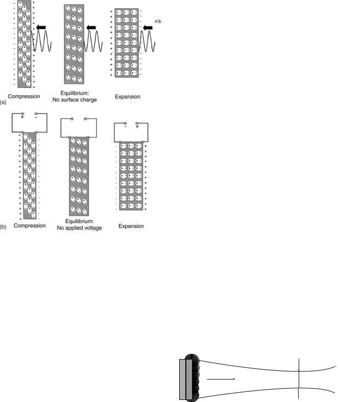
Piezoelectric crystals are able to contract or expand when an electrical field is applied to them because dipoles within the crystal lattice will realign themselves as a result of attractive and repulsive forces causing a change in physical dimension of the material in the order of nanometers (electrostriction or reverse piezoelectric effect). When echos are received, the ultrasound waves will compress and expand the crystals (8). This mechanical stress causes the dipoles to realign on the crystal surface creating a net charge (piezoelectric effect) (Fig. 1).
Transducers function optimally when there is broad bandwidth in the frequency domain and short impulse response in the time domain. Also, when there is little electroacoustical conversion inefficiency, and little mismatch between the electrical impedances of the generator and the transducer (3,9). A transducer’s ability to transmit energy is dependent on the characteristics of acoustic impedances and its contact medium. Both the density of the material and propagation velocity of ultrasound waves will determine its impedance. When both impedances match, then less energy is lost through reflection back into the transducer. For example, at the interface between air and the transducer, most of the energy will be reflected back to the transducer and will travel to the opposite direction because air has 16 times less impedance than the transducer. If the transducer is a half wavelength in thickness, the reflected wave arrives at the opposite surface in phase with the direction of its motion and can then be transmitted into the medium. Since the efficiency at which a transducer transmits energy has a direct relationship to the degree of impedance match, efficiency can be increased significantly by adding an impedance matching layer of a quarter wavelength thickness, subsequently making the characteristic impedance equal to the geometric average of those of the transducer and the loading medium (3,8).
RADIATION FIELD OF ULTRASONIC TRANSDUCERS
The radiation field of an ultrasonic transducer depends on its physical properties and the transmission characteristics of the medium through which it will pass. Conventional planar transducers create a nonfocused field, whereas some modifications to the same transducer can create a focused field.
NONFOCUSED FIELDS
Planar Transducers
Ultrasonic waves that are radiated from the transducer surface can be described as a tightly packed array of
64 HYPERTHERMIA, ULTRASONIC
Figure 1. A piezoelectric compound consists of aligned molecular dipoles. (a) At equilibrium, the dipoles are arranged in a configuration that results in a neutral net charge. When the piezoelectric compound is mechanically stressed (e.g., an ultrasound wave) the element changes its physical dimensions. At peak pressure amplitudes, the element will contract. When no stress is placed upon the element it is in equilibrium. At peak rarefaction, the element will expand. This realignment of dipoles results in the production of a net positive or negative surface charge. (b) When an electrical field is applied to the piezoelectric element the dipoles can be realigned in response to attractive or repulsion forces. This rearrangement results in either expansion or contraction of the element. In the absence of an applied electrical field the element is in equilibrium and has a neutral net charge. (Published with the permission from Ref. 8).
separate point sources of sound energy (Fig. 2a). Each of these points emits a spherical wavelet (Fig. 3). These waves interact both constructively and destructively creating a diffraction pattern. Any point in the medium is a compilation of all the sources that reach that target at that period of time. This diffraction pattern can be calculated using Huygen’s principle. Two separate transducers whose emission fields interact in the same media are subject to the same laws of construction and destruction. Planar transducers operating in continuous wave mode are shown in (Fig. 2). In the Fresnel zone or the near field, the beam energy distribution is collimated, which is a result of the many destructive and constructive interactions of the spherical wavelets (Figs. 2c and 3). The
Figure 2. A planar transducer operating in a continuous wave mode. (a) The envelope containing almost all of the ultrasonic energy. (b) The relative intensity of the ultrasonic beam along a central axis. The intensity across the field fluctuates greatly at small distances from the surface of the transducer. At greater distances along the central axis the intensity distribution across the field stabilizes and deteriorates with beam divergence. (c) Ring diagrams illustrating the energy distribution at positions indicated in (b). In the near field, the ring beam pattern is collimated, but at greater distances from the transducer surface the beam diverges. (Published with permission from Ref. 3).
beam path is a function of the dimension of the active part of the transducer surface, thus the beam diameter that is converging at the end of the near field is approximately one-half of the size of transducer diameter. The intensity and pressure amplitudes fluctuate greatly at small distances from the surface transducer (Fig. 2b). As the distance from the transducer surface increases, the beam path diverges (Fig. 2c and 3). In large diameter, high frequency transducers, there is less beam divergence in the far field. After a certain distance from the transducer surface, the intensity stabilizes; however, intensity along the axis deteriorates along with beam divergence (Fig. 2b). Circular, square, and rectangular transducers have similar fields; albeit, circular transducers have more pronounced fluctuations of intensity in the near field (3,8).
Constructive and destructive interference
 patterns confine beam in the near field
Near field |
Far field |
Direction of beam
Figure 3. Ultrasonic waves that are radiated from the transducer surface are described as a tightly packed array of separate point sources. Each of these points radiates a spherical wavelet (Huygen’s principle). These spherical wavelets will interact constructively and destructively. In the near field, these interactions result in a convergent beam pattern. In the far field, the beam pattern diverges. (Published with permission from Ref. 8).
FOCUSED FIELDS
Single-Element Transducers
When an ultrasonic wave travels through different media, the laws of geometric optics can be applied. Ultrasonic waves can be reflected, refracted, and scattered. When there is a high degree of impedance mismatch between the generator and transducer, ultrasonic waves will be reflected back into the transducer. The angle of reflection is equal to the angle of impedance, much like that of a mirror. Single element transducers can be focused by using a curved acoustic lens or a curved piezoelectric element (8). When an ultrasonic wave goes through two media with different propagation velocities there is a certain degree of refraction. Ultrasonic propagation through water is 1500 m s 1. In order to focus the ultrasound field, a lens of plastic (e.g., polystyrene), which has a higher propagation velocity, is placed between the transducer and the water media; these converging lenses are then concave to the water media and at plane with the transducer interface. In an unfocused transducer, the focal length is directly proportional to the transducer frequency and diameter. In a focused single element transducer, the focal distance is brought closer to the transducer surface. The focal distance is defined as the distance between the transducer surface and the portion of the beam that is narrowest. The focal zone, which is the area of best lateral resolution, is defined as the area at which the width of the beam is less than two times the width at the focal distance (3,8) (Fig. 4). The focal zone is dependent on the aperture and the wavelength of the ultrasound. The focal area through which 84% of the ultrasound passes is two to four wavelengths in hyperthermia systems. With ultrasonic transducers, the intensity distribution dimensions are a function of frequency and aperture. Therefore, the larger the aperture, the shorter the focal region, the higher the frequency and the smaller the diameter of the beam (Fig. 5). Ceramic curved bowl-shaped transducers, while more efficient than a lens, do not have the versatility of a lens. Once a ceramic bowl is fabricated, the focal length is set. Lenses can be interchanged creating a variety of focal lengths with one transducer (8).
HYPERTHERMIA, ULTRASONIC |
65 |
2.7 MHz
(mm)Vertical |
100% |
85% |
|
70% |
|||
|
|
||
|
|
50% |
|
|
|
20% |
Lateral (mm)
Figure 5. The intensity distribution in the focus of an ultrasound transducer. The diameter and the length are a function of frequency. The lower the frequency, the larger the diameter, and the smaller the aperture, the longer the focal region. (Published with permission from Ref. 3).
|
|
|
|
|
|
|
|
|
|
|
|
|
|
|
|
|
|
|
|
|
Curved element |
Focal zone |
|||||
Figure 4. The focal zone is the area of optimal lateral resolution. The use of a curved element or an acoustic lens allows the focal distance to be brought closer to the transducer surface. The use of a curved element decreases the beam diameter at the focal distance and increases the angle of beam divergence far field. The focal zone, which is the are of best lateral resolution, is defined as the area at which the width of the beam is less than two times the width at the focal distance. (Published with permission from Ref. 8).
Multielement Transducers
Linear array transducers contain 256–512 narrow piezoelectric elements. They produce a beam by firing a portion of the total number of elements as a group. If a single element were fired the beam pattern would be divergent in the near field. By firing a group of elements, it is possible to focus and converge the beam. All the individual beams interact both constructively and destructively to produce a collimated beam. A phase array transducer is composed of 64–128 elements. The ultrasound beam can be steered and focused without moving the transducer by electrically activating the separate elements on the transducer surface at slightly different times (8).

66 HYPERTHERMIA, ULTRASONIC
Table 1. Acoustic Impedancea
Tissue |
Z, rayls |
|
|
|
|
|
|
6 |
Air |
0.0004 |
106 |
Lung |
0.18 |
106 |
Fat |
1.34 |
106 |
water |
1.48 |
106 |
Kidney |
1.63 |
106 |
Blood |
1.65 |
106 |
Liver |
1.65 |
106 |
Muscle |
1.71 |
106 |
Skull bone |
7.8 |
10 |
aMeasured in rayls. z ¼ pc (z ¼ impedance, p ¼ sound pressure, c ¼ speed of sound), for air, water, and selected tissues. (Published with permission from Ref. (8).
PROPAGATION OF ULTRASOUND IN BIOLOGICAL TISSUES
The journey of an ultrasound wave through human tissue is sometimes arduous. As the waves propagate through different biological media, they are subject to reflection, refraction, scattering, and absorption (8). When there is a difference in acoustic impedance between the boundaries of two tissues, reflection occurs (Table 1). There is 100% reflection at the air–skin interface. However, if a coupling medium (e.g., gel) is used, reflection is reduced to 0.1%. When the beam is not perpendicular to tissue boundary, the transmitted ultrasound energy undergoes a change in direction at the boundary; this directional change is termed refraction. As waves propagate through tissue they must overcome internal friction resulting in a loss of energy. The mechanical energy that is lost is converted to heat, which is termed absorption. At higher frequencies, ultrasonic waves move quicker, thus forcing the molecules to move against each other creating friction. The more these molecules move, the more energy is consumed or absorbed, and subsequently will be converted to heat. The speed at which the ultrasonic wave travels is dependent on the arrangement of the molecules. If they are densely arranged, they will collide sooner when they are exposed to a stimulus, and will lose energy quickly and at shorter distances. Ultrasonic waves can travel through the skin without much absorption until they reach tissues with high collagen content, (e.g., bone, periosteum, ligaments, capsules, fascia, and tendons). Ultrasonic waves travel through most solid tissues at a speed of 1500–1600 m s 1. Its velocity in fat and postmenopausal breast tissue may be as low as 1450 m s 1 and the lens of the eye 1600 m s 1. As a general rule, ultrasonic waves move through soft tissue with relatively little reflection or refraction (3,8) (Table 2).
Ultrasonic speed through bone is 4080 m s 1. Bone easily absorbs ultrasonic energy and reflects it to tissues that are located at the bone–tissue interface. Since bone absorbs ultrasonic energy so readily, it heats up very quickly, consequently making it harder to control temperature. Thus, bone and its immediate surrounding tissue were once considered problematic for therapeutic use of ultrasonic hyperthermia (3,8). Nevertheless, in a recent study, Moros et al. noted that the presence of underlying
Table 2. Density and Speed of Sound in Tissues and Materials for Medical Ultrasound.a
Material |
Density, kg m 3 |
c, m s 1 |
c, mm s 1 |
Air |
1.2 |
330 |
0.33 |
Lung |
300 |
600 |
0.60 |
Fat |
924 |
1450 |
1.45 |
water |
1000 |
1480 |
1.48 |
Soft tissue |
1050 |
1540 |
1.54 |
Kidney |
1041 |
1565 |
1.57 |
Blood |
1058 |
1560 |
1.56 |
Liver |
1061 |
1555 |
1.55 |
Muscle |
1068 |
1600 |
1.60 |
Skull bone |
1912 |
4080 |
4.08 |
PZTb |
7500 |
4000 |
4.00 |
aPublished with permission from Ref. 8. bPZT, lead cisconate .inanate
bone in superficial unfocused ultrasound hyperthermia could actually be exploited to induce more uniform and enhanced temperature distributions in superficial target volumes. In particular, they have shown that the presence of bone in superficial target volumes enhances temperature elevation not only by additional direct power deposition from acoustic reflection, but also from thermal diffusion from the underlying bone (10).
The intensity at which an ultrasonic beam is transmitted has an effect on target tissue temperature. Intensity is defined as the amount of power per unit area. Doubling the amount of power used will result in quadrupling the intensity. Ultrasonic waves will lose intensity as they propagate further into the tissue. The attenuation coefficient is the relative intensity loss per centimeter of travel in a given medium (Table 3). Beam divergence, absorption, and scattering will also cause a loss in intensity of the propagating beam. The absorption coefficient of the tissue being exposed to us determines the target temperature that tissue will reach. The absorption coefficient is dependent on the density of the tissue and will linearly increase at higher frequencies. The absorption coefficient in soft tissue is 4–10 times lower than that of bone, and therefore bone heats more quickly (3). At short exposure times (e.g., < 0.1 s), temperature and intensity are directly propor-
Table 3. Attenuation Coefficients for Selected Tissues at 1 MHz.a
Tissue |
Attenuation Coefficient |
Composition |
1 MHz beam, dB cm 1 |
Water |
0.0002 |
Blood |
0.18 |
Soft tissues |
0.3–0.8 |
Brain |
0.3–0.5 |
Liver |
0.4–0.7 |
Fat |
0.5–1.8 |
Smooth muscle |
0.2–0.6 |
Tendon |
0.9–1.1 |
Bone, cortical |
13–26 |
Lung |
40 |
aPublished with permission from Ref. 8.
tional. However, as the time intervals increase, other factors in addition to intensity, (e.g., blood perfusion), must be considered. An approximate estimate of the ultrasonic energy requirements for heating a target volume to therapeutic temperature depends on assessing thermophysical properties of that tissue, intensity of the ultrasound beam, ultrasonic absorption coefficient, and additional factors (e.g., blood circulation to target tissue) (3,8,11). The thermal index is defined as the ratio of acoustic power created by the transducer to raise the target area by 1 8C. This is calculated by using an algorithm that takes into account the ultrasonic frequency, beam area, and the acoustic power output of the transducer (8).
Ultrasonic waves act on tissues thermally and mechanically. Mechanical effects on tissues via ultrasound include acoustic torque, acoustic streaming, radiation force, stable cavitation, and unstable cavitation (11). Any object situated within an acoustic field will be subject to acoustic pressure and acoustic force. Acoustic pressure in a standing wave field is inversely proportional to velocity. Acoustic torque results from variations in the acoustic field, which can be described as a time-independent twisting action. Acoustic torque causes a rotational movement of cells and intracellular organelles in the medium. Acoustic streaming describes the movement of fluid in an ultrasonic field. The compression phase of an ultrasonic wave deforms tissue molecules. Radiation force affects gas bubbles that are in the tissue fluids. Negative pressure induces the bubbles originally dissolved in the medium to fall out of solution. With positive and negative pressure wave fluctuations, these bubbles expand and contract without reaching critical size (stable cavitation). Unstable cavitation occurs when bubbles collapse violently under pressure after growing to critical size due to excessive energy accumulation. This implosion produces large, brief local pressure and temperature release, as well as causing the release of free radicals. Organs that are air-filled, (e.g., the lungs or intestines), are subject to greater chance of unstable cavitation. Unstable cavitation is somewhat random, and as such it may lead to uncontrollable tissue destruction (8,11). Bubble growth can be limited by low intensity, high frequency, and pulsed ultrasound. Higher frequency means shorter cycle duration so time for bubble growth is regulated. Pulsed ultrasound restricts the number of successive growth cycles and allows the bubble to regain its initial size during the off period. The mechanical index estimates the possibility of cavitation occurrence. The mechanical index is directly proportional to peak rarefaction pressure, and inversely proportional to the square root of the ultrasound frequency (8).
MEDICAL APPLICATIONS OF CONVENTIONAL HYPERTHERMIA
Ultrasound as a heating modality has been used in several different medical fields. It is used in treating sprains, bursitis, joint inflammation, cardiac ablations, and in gynecology. However, the main area conventional hyperthermia is currently used is in oncology. The use of conventional hyperthermia as an oncologic treatment is
HYPERTHERMIA, ULTRASONIC |
67 |
supported by a plethora of studies that demonstrate that heat on cell lines and on animal tumor transplant models can result in tumor regression; however, it is rarely used alone because its efficacy is greatly potentiated in combination with radiation or chemotherapy. Conventional hyperthermia treatments elevate target tissue temperatures to 42–46 8C (12). Treatment times are usually between 30 and 60 min. Treatment applications are administered once or twice a week and are applied in conjunction with or not long after radiation. In all of the recent phase III trials, a sequential delivery scheme was used. This means that radiation and hyperthermia were administered separately, with radiation preceding hyperthermia treatments (13). Tumoricidal effects in vivo are achieved at temperatures between 40 and 44 8C (5). Large tumors often have an inadequate blood supply and resultantly, have difficulty meeting their requirements for oxygen and nutrients. This situation creates a hypoxic environment that is low in pH (2–3) (3,5,14). When tumor cells are heated to therapeutic temperatures, their cellular metabolic processes are accelerated, thereby further increasing the demands for oxygen and nutrients in an already depleted environment. Most tumor cells are unable to reproduce in this hostile environment, resulting in termination of tumor growth and shrinkage of the tumor (5,15). In temperatures > 40 8C, protein denaturation has been observed as the main mechanism of cellular death. Widespread protein denaturation results in structural changes in the cytoskeleton and the cell membrane, and in enzymes that are necessary for deoxyribonucleic acid (DNA) synthesis, cellular division, and cellular repair (5). Hyperthermic efficacy is a function of temperature and exposure time. To quantify, at temperatures > 42.5– 43 8C, the exposure time can be halved with each 1 8 temperature increase to give an equivalent cell kill (5,16). Healthy tissues remain undamaged at temperatures of 44 8C for a 1 h duration (5,17). The exceptions are central nervous tissues, which suffer irreversible damage after being exposed to heat at temperatures ranging from 42 to 42.5 8C for >40–60 min (5,18). Peripheral nervous tissue that has been treated for > 30 min at 44 8C or an equivalent dose results in temporary functional loss that is reversed in 4 weeks (5,19). Therefore, since a small difference in temperature produces a large difference in the amount of cells killed, it is important to be able to have good control on the site and duration of heat delivery to reduce the damage to surrounding healthy tissue.
RADIATION COUPLED WITH CONVENTIONAL HYPERTHERMIA
While hyperthermia independently has been found to have antitumor effects, its efficacy is greatly potentiated when coupled with radiation. Cells that are in a low pH hypoxic environments, those that are in the S or M phases of cell division, and those that are malnourished are relatively resistant to radiation (5,7). Hyperthermia increases radiation damage and prevents cellular repair of damaged DNA (5,16). Hyperthermia increases blood perfusion via
68 HYPERTHERMIA, ULTRASONIC
vasodilation which results in increased oxygenation, thus allowing increased radiosensitivity (5,7,16). Response rates with hyperthermia alone are 15%, with radiotherapy 35%, with combined radiotherapy, and hyperthermia70% (20). There have been many U.S. and European clinical trials that support substantial improvement in patients who have been treated with a combination of radiation and hyperthermia. Examples of some recent trials include randomized multiinstitutional phase III trials for treating melanoma (20,21), glioblastoma multiforme (20,22), chest wall recurrence of breast cancer (20,23), head and neck cancer (20,24,25), head and neck in superficial measurable tumors (20,26,27), in various recurrent persistent tumors (20,28), cervical cancer (29), uterine cancer (30) and in locally advanced pelvic tumors (20,31) (Table 4). Trial success rates were very dependent on the uniformity of temperature delivery. In the past, trials had often provided mediocre results because temperatures were 1–1.5 8C too low and consequently not able achieve adequate tumoricidal levels (7). It is often difficult to uniformly heat larger tumor (3,7). When radiation and hyperthermia are used simultaneously excellent radiation delivery is achieved, often resulting in tumor regression; however, its delivery is equally as toxic to healthy cells that necessitate the need for a very precise delivery system.
CHEMOTHERAPY IN CONJUNCTION WITH
CONVENTIONAL HYPERTHERMIA
Chemotherapeutic efficacy is enhanced by hyperthermia (5,20,34,35) (Table 5). As areas are heated, perfusion is increased, thus allowing an increase in drug concentrations in areas of the tumor that are poorly vascularized, increased intracellular drug uptake, and enhanced DNA damage. Drugs (e.g., mitomycin C, nitrosureas, cisplatin, doxorubicin, and mitoxantrone) are subject to less drug resistance when used with heat. The synergistic effect of chemotherapy and hyperthermia was demonstrated in virtually all cell lines treated at temperatures >40 8C for alkylating drugs, nitroureas, and platin analogs dependent on exposure time and temperature. Chemotherapeutic agents can be revved up 1.2–10 times with the addition of heat (5). In vivo, experiments showed improvement when doxorubicin and mitoxantrone were combined with hyperthermia. However, antimetabolites vinblastine, vincristine, and etoposide did not show improvement with the addition of hyperthermia. In animal studies, increased toxicities were seen in skin (cyclophosphamide, bleomycin), heart (doxorubicin), kidney (cisplatin, with a core temperature >41 8C), urinary tract (carmustine, with core temperatures >41 8C), and bone marrow (alkylating agents and nitroureas) (5,34). Lethal toxicity was enhanced when systemic hyperthermia was applied in combination with cyclophosphamide, methyl-CCNU, and carmustine (5). The success of hyperthermia and chemotherapy combinations depends on the temperature increase in the organs for which the drug is used and its subsequent toxicity, all of which are can be influenced by the accuracy of the heating device and the operator.
MODES OF CONVENTIONAL HYPERTHERMIA APPLICATION
Externally Applied Techniques
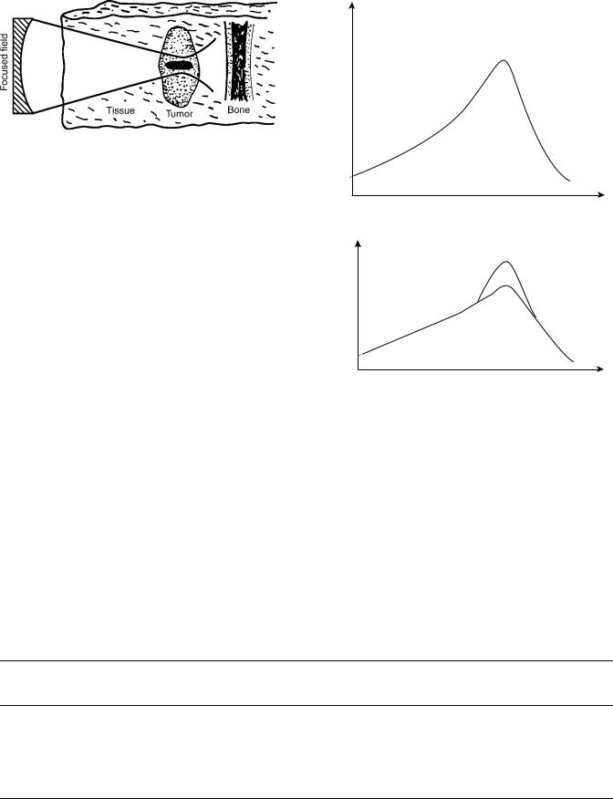
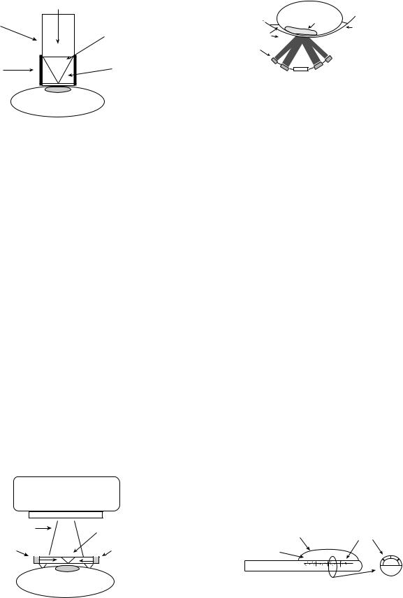
In the past, single planar transducers were used to apply local heat. A disk shaped piezoelectric transducer (range from 0.3–6.0 MHz in frequency and up to 16 cm in diameter) is mounted above a chamber of cooled degassed water. This device has a coupling chamber which allows water to circulate (3) (Fig. 6). It is coupled to the body via a plastic or latex membrane. Unfortunately, these types of devices are unable to achieve homogenous therapeutic thermal levels. The reason is that this system uses an unfocused energy source. When an unfocused energy source is applied to the skin, the intensity and the temperature will be the highest at the contact point and will subsequently lose intensity as it travels deeper into the tissue. However, by cooling the skin, the ‘‘hot spot’’ is shifted to the subcutaneous fatty tissue that is poorly vascularized. Fat is an insulator and as a result much energy is conserved rather than lost. Furthermore, cooling the skin will produce vasoconstriction which conserves even more heat and facilitates the heating of deeper tissues
(3) (Figs. 7, 8a and b). However, even with this strategy adequate temperatures could not be reached. The reason for this is that large tumors often consist of three zones, a central necrotic core, an intermediate zone that is normally perfused, and a marginal zone that has a greater number of vessels due to proliferation induced angiogenesis. Due to the abundance of vasculature on the marginal surface, much heat is dissipated to the surrounding tissue. The relatively avascular center will heat to a higher temperature than the marginal or intermediate zone because there is little dissipation of heat, creating hot spots (Fig. 9) (7,54). Thus, it is not possible to therapeutically heat a tumor with a single planar source. This theory is substantiated by a significant number of clinical trials (7,55–61). Most trials reported that patients had some difficulty with doselimiting pain, extensive central tumor necrosis, blistering, and ulceration (7). Conversely, a focused ultrasound source localizes energy within the tumor volume while sparing the surrounding tissue (Fig. 10). The use of a focused beam allows for homogenous heating and higher intensity which allows the generation of greater temperatures within the target area. Attenuation and beam divergence cause rapid deterioration of intensity beyond the focal zone (3) (Fig. 11 a and b). Focused ultrasound sources overcome some of the limitations of planar heating. Focusing allows for controlling the amount of heat that is delivered to the poorly perfused areas thus limiting hot spots and some of the side effects. For a heating system to be successful clinically on a large scale, it must account for geometric and dimensional variations of target tissue, possess the ability to heat the sites that need it, and avoid side effects and complications as much as possible (3).
Technological advances in hyperthermia devices have paved the way for better therapeutic options. The use of mosaics or separately controlled transducers allowed better spatial and temperature control to target bulky irregularly shaped tumors. The multielement planar

|
|
|
|
|
HYPERTHERMIA, ULTRASONIC |
69 |
||
Table 4. Hyperthermia and Radiation Clinical Trials |
|
|
|
|
|
|
||
|
|
|
|
|
|
|
|
|
Reference/ |
|
|
|
|
Results of |
Results of |
Significance |
|
name of |
|
|
No. of |
Type of |
Control Arm |
Hyperthermia |
of Results |
|
trial |
Tumor Entity (stage) |
Type of Trial |
Patients |
Hyperthermia |
(RT only)a |
Arm (RTþHT)a |
( p<0.05) |
|
(26,32) |
Head and neck |
Prospective |
106 |
Superficial |
34% CR |
34% CR |
|
|
RTOG |
(superficial measurable |
randomized |
|
(915 MHz |
|
|
|
|
|
tumor) |
multicenter |
|
microwave) |
|
|
|
þ |
(25) |
Head and neck untreated |
Prospective |
65 |
Superficial |
32% DR |
55% CR |
|
|
|
locoregional tumor |
randomized |
|
(27-12 MHz |
|
|
|
|
|
|
|
|
microwave) |
|
|
|
þ |
|
|
|
|
|
19% DFS at |
33% DFS |
|
|
|
|
|
|
|
1.5 years |
at 1.5 years |
|
þ |
(24,33) |
Head and neck |
Prospective |
41 |
Superficial |
41% CR |
83% CR |
|
|
|
(N3locoregional tumor) |
randomized |
|
(280 MHz |
|
|
|
|
|
|
|
|
microwave) |
|
|
|
þ |
|
|
|
|
|
24% LRFS |
68% LRFS |
|
|
|
|
|
|
|
0% OS at |
53% OS at |
|
þ |
|
|
|
|
|
5 years |
5 years |
|
þ |
(21) ESHO-3 |
Melanoma (skin |
Prospective |
70 |
Superficial |
35% CR |
62% CR |
|
|
|
metastases or recurrent |
randomized |
|
(various |
|
|
|
|
|
skin lesions) |
Multicenter |
|
techniques) |
|
|
|
þ |
|
|
|
|
|
28% LRFS at |
46% LRFS at |
|
|
|
|
|
|
|
5 years |
5 years |
|
þ |
(23) MRC/ |
Breast cancer (local |
Randomized |
306 |
Superficial |
41% CR |
59% CR |
|
|
ESHO-5 |
recurrences or inoperable |
multicenter |
|
(various |
|
|
|
|
|
primary lesions) |
|
|
techniques) |
|
|
|
þ |
|
|
|
|
|
ca. 30% LRFS |
ca. 50% LRFS |
|
|
|
|
|
|
|
ca. 40% AS |
ca. 40% AS at |
|
|
|
|
|
|
|
at 2 years |
2 years |
|
|
(31) |
Rectal cancer |
Prospective |
143 |
Deep regional |
15% CR |
21% CR |
|
|
|
|
randomized |
|
HT (various |
|
|
|
|
|
|
multicenter |
|
techniques) |
|
|
|
|
|
|
|
|
|
22% OS at |
13% OS at |
|
|
|
|
|
|
|
3 years |
3 years |
|
þ |
|
Bladder cancer |
|
101 |
|
51% CR |
73% CR |
|
|
|
|
|
|
|
22% OS at |
28% OS at |
|
|
|
|
|
|
|
3 years |
3 years |
|
þ |
|
Cervical cancer |
|
114 |
|
57% CR |
83% CR |
|
|
|
|
|
|
|
27% OS at |
51% OS at |
|
þ |
|
|
|
|
|
3 years |
3 years |
|
|
(28) |
Various (recurrent or |
Prospective |
174 |
Interstitial HT |
54% CR |
57% CR |
|
|
|
progressive lesions) |
randomized |
|
(300-2450 MHz |
|
|
|
|
|
|
multicenter |
|
microwave |
|
|
|
|
|
|
|
|
or RF) |
|
|
|
|
|
|
|
|
|
34% OS at |
35% OS at |
|
|
|
|
|
|
|
2 years |
2 years |
|
þ |
(25) |
Gioblastoma |
Prospective |
79 |
Interstitial HT |
15% OS at |
31% OS at |
|
|
|
(postoperative) |
randomized |
|
|
2 years |
2 years |
|
þ |
(29) |
Stage IIIB |
Prospective |
40 |
Deep regional |
50% CR |
80% CR |
|
|
|
uterine cervix |
randomized |
|
HT |
|
|
|
|
|
|
|
|
|
45% CR at |
79.7% CR at |
|
|
|
|
|
|
|
3 years |
3 years |
|
þ |
(27) |
Superficial tumors |
Prospective |
122 |
EM |
42.3% CR |
66.1% CR |
|
|
|
|
randomized |
|
|
|
|
|
þ |
(30) |
Uterine cervical |
Prospective |
110 |
RF |
68.5% CR |
73.2% CR |
|
|
|
|
randomized |
|
|
|
|
|
|
|
|
multicenter |
|
|
|
|
|
|
aAS ¼ actuarial survival; CR ¼ complete remission; DFS ¼ disease free survival; HT ¼ hyperthermia; LRFS ¼ local relapse free survival; OS ¼ overall survival; RF ¼ radio frequency electric currents; RT ¼ radiotherapy. (Published with permission from Ref 20).
ultrasound applicators met these demands and are capable of treating tumors at depths up to 8 cm. The multisector applicator allows for heating to the edge of the aperture and the acoustic beams are nondiverging in the near field,
thus allowing large tumor heating with lateral measurements of 15 15 cm. Each of these 16 sectors can be varied from 0 to 100% power to uniformly heat across the tumor. If an area of the tumor is too difficult to treat, more energy

70 |
HYPERTHERMIA, ULTRASONIC |
|
|
|
|
|
||
Table 5. Hyperthermia and Chemotherapy Clinical Trials |
|
|
|
|||||
|
|
|
|
|
|
|
|
|
|
|
|
Type of |
No. of |
Type of |
Type of |
|
|
Reference |
Tumor Entity |
Trial |
Patients |
Hyperthermiaa |
Chemotherapya |
Resultsa |
||
|
|
|
|
|
|
|
|
|
(36) |
|
Oesophagus |
Phase II |
32 |
localHT/ |
CDDP þ Bleo þ |
8 CR/13 PR |
|
|
|
cancer |
|
|
Endoluminal MW |
Cyc |
(65% RR) |
|
|
|
(preoperative) |
|
|
|
CDDP þ Bleo |
|
|
(37) |
|
Oesophagus |
Phase III |
20 |
localHT/ |
1 CR/5 PR/4 MR |
||
|
|
cancer |
|
|
Endoradiotherm |
|
|
(50% RR); |
|
|
(preoperative) |
|
|
|
CDDP þ Bleo |
FHR (41.2%) |
|
|
|
|
|
20 |
Control |
0CR/5 PR/0 MR |
||
|
|
|
|
|
|
|
|
(25% RR); |
|
|
|
|
|
|
|
þ 5FU |
FHR (18.8%) |
(38) |
|
Stomach cancer |
Phase II |
33 |
RHT/thermotron |
Mitomycin |
3 CR þ 10 PR |
|
|
|
|
|
|
|
|
þ 5FU |
(39% RR) |
|
|
pancreatic cancer |
|
22 |
8 MHz |
Mitomycin |
3 CR þ 5 PR |
|
|
|
|
|
|
|
Mitomycin þ 5FU þ/ |
(36% RR) |
|
(39) |
|
Pancreatic cancer |
Phase II |
77 |
RHT 13.5 MHz |
27..3% survival |
||
|
|
|
|
|
|
- immunostimulation |
at 1 year |
|
(40,41) |
|
Sarcomas |
Phase II |
38 |
RHT/BSD 1000 |
VP16 þ IFO |
6 pCR þ 4PR þ 4FHR |
|
|
|
(pretreated with |
(RHT 86) |
|
60-110 MHz |
|
|
(37% RR) |
|
|
chemotherapy) |
|
|
|
VP16 þ IFO |
9pCR þ 4PR þ 8FHR |
|
|
|
|
Follow-up |
65 |
|
|||
|
|
|
|
|
|
VP16 þ IFO þ ADR |
(32% RR) |
|
(42,43) |
|
High risk soft |
Phase II |
59 |
RHT/BSD 2000 |
ICR/6pCR þ 8PR þ 13 MR |
||
|
|
tissue sarcomas |
(RHT 91) |
|
80-110 MHz |
|
|
(47%) |
|
|
|
|
|
|
VP16 þ IFO þ ADR |
OS: 46% at 5 years |
|
(44) |
|
High risk soft |
Phase III |
112 |
RHT/BSD 2000 |
(08/00) |
||
|
|
tissue sarcoma |
(EORTC |
|
80-110 MHz |
|
|
|
|
|
|
62961) |
|
(randomized) |
TNF þ IFN þ L-PAM |
|
|
(45) |
|
Soft tissue |
Phase II |
55 |
ILP with HT |
10CR/35PR (82% RR) |
||
|
|
sarcoma |
|
|
|
IFO þ CBDCA |
|
|
(46) |
|
Sarcoma/ |
Phase I/II |
19 |
WBH |
6PR (32% RR) |
||
|
|
teratomas |
|
|
|
|
|
|
|
|
(metastatic) |
|
|
|
IFO þ CBDCA þ VP16 |
|
|
(47) |
|
Sarcoma |
Phase II |
12 |
WBH |
7PR (58% RR) |
||
|
|
(metastatic) |
|
|
|
|
|
|
(48) |
|
Refractory |
Phase I |
16 |
WBH |
L-PAM |
ICR/2PR (19% PR) |
|
|
|
cancers |
|
|
(Aquatherm) |
(dose-escalation) |
|
|
|
|
(advanced or |
|
|
|
|
|
|
|
|
metastatic) |
|
|
|
V16 þ IFO þ CBDCA |
|
|
(49) |
|
Pediatric |
Phase II |
34 |
RHT/BSD 2000 |
12 NED |
||
|
|
sarcomas |
|
|
80-110 MHz |
|
|
(‘best response’)/ |
|
|
|
|
|
|
|
|
7 CR Duration: |
|
|
|
|
|
|
CDDP þ VP16 þ IFO |
7-64 months |
|
(50) |
|
Pediatric |
Phase II |
10 |
RHT/BSD 2000 |
5CR þ 2PR |
||
|
|
nontesticular |
|
|
80-110 MHz |
(¼PEI) |
(70% RR) Six |
|
|
|
germ cell |
|
|
|
|
|
patients alive |
|
|
tumours |
|
|
|
|
|
without evidence |
|
|
|
|
|
|
|
|
of tumour |
|
|
|
|
|
|
|
|
(10-33 months) |
(51) |
|
Cervical cancer |
Phase II |
23 |
RHT/array-system |
CDDP (weekly) |
2pCR/ICR þ 9PR |
|
|
|
(recurrences) |
|
|
70 MHz |
|
|
(52% RR) |
(52) |
|
Rectal cancer |
Phase II |
27 |
Intraoperative IHP |
Mitomycin C |
3 LR |
|
|
|
(Dukes C |
|
35 |
Control |
Mitomycin C |
13LR |
|
|
|
preoperative) |
|
|
|
|
|
|
(53) |
|
Metastatic Sarcoma |
Phase II |
108 |
whole body |
IFO/CBDCA/VP16 |
68% success at 1 year |
|
|
|
|
|
|
Hyperthermia |
|
|
|
aP ¼ intraoperitoneal hyperthermic perfusion; WBH ¼ whole body hyperthermia; 5FU ¼ 5-flurouracil; VP16 ¼ etoposide; IFO ¼ ifosfamide;
ADR ¼ Adriamycin ¼ Doxorubin; CDDP ¼ Cisplatin; CBDCA ¼ Carboplatin; Bleo ¼ Bleomycin; L-PAM ¼ Melphan; TNF ¼ tumor necrosis factor alpha; IFN ¼ interferon gamma; p ¼ pathohistological; RR ¼ response rate; CR ¼ complete remission; PR ¼ partial remission; MR ¼ minor response;
FHR ¼ favorable histological response >75%; LR ¼ local recurrence; NED ¼ no evidence of disease.(Published with permission from Ref. 20).

|
RF |
|
|
input |
Cooling |
|
|
water |
|
|
outlet |
|
Cooling |
|
|
channel |
|
|
Piezoeletric |
|
|
element |
|
25 cm |
Cooling |
Cooling |
water |
||
|
baffle |
inlet |
|
|
|
|
Latex |
Retaining |
|
membrane |
|
|
|
‘O’ ring |
|
10 cm |
|
Figure 6. A cross-sectional diagram of a single planar element hyperthermia applicator. The chamber between the latex membrane and the piezoelectric element contains cooled degassed water. During local hyperthermia treatment an ultrasonic conducing gel is applied to the target site that is then coupled to the latex membrane. (Published with permission from Ref. 3).
can be directed to just that target segment. The temperatures can be adjusted in relation to variations in temperature distribution due to blood flow, variations in target tissue morphology, and based on the patient’s comfort level. These devices have the ability to contour the energy field to match the tumor outline. These systems generally have two frequencies: 1 MHz (used to heat 3–6 cm) and 3.4 MHz (used for more superficial 2–3 cm) (7,62). Examples of heating temperatures for different ultrasound hyperthermia devices are shown (Table 6). These planar array systems have been adapted to allow for thermoradiation in conjunction with an external beam radiation (7). An extended bolus configuration with an internal reflecting system was created to direct the ultrasound energy into desired tissue. This configuration allows the ultrasound transducer to be outside the radiation beam thus preventing potential interference of the two (7,70).
Another approach to achieving greater spatial control is to use a larger variety of small transducers in a nonplanar geometric configuration. This approach has been used in
Plane wave energy
Tissue Tumor
Figure 7. The pattern of ultrasound delivery via plane wave radiation targeting a tumor that is located deep within the tissue. (Published with permission from Ref. 3).
HYPERTHERMIA, ULTRASONIC |
71 |
(a)
|
I |
|
I o |
Intensity |
I = Ioe – mx |
|
|
|
|
Depth, x |
(b) |
|
|
|
|
|
|
|
|
No cooling |
|
|
|
|
|
|
|
|
|
|
Temperature |
|
|
|
Skin cooling |
rise |
|
|
|
|
|
|
|
|
|
|
|
|
|
Depth, x |
Figure 8. (a) Ultrasound intensity is greatest at the surface. Intensity will deteriorate exponentially due to attenuation as the depth from the surface increases. Published with the permission of
(3). (b) Since temperature and intensity are directly proportional, temperature will decrease exponentially as depth increases. Cooling the skin will cause the ‘‘hot spot’’ to shift to the poorly perfused fatty tissue. (Published with permission from Ref. 3).
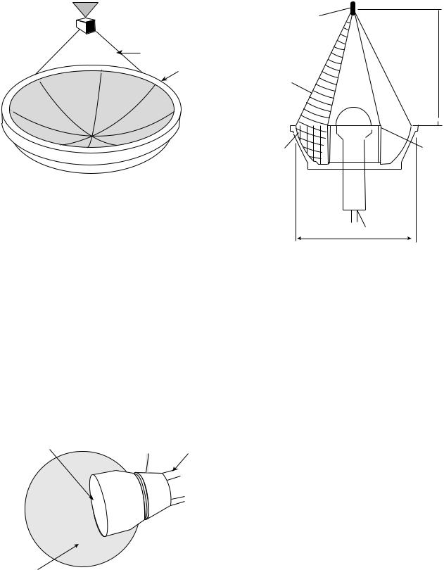
treating intact breast with cancer (7,71). The patient lies prone while the breast is immersed within the water filled cylindrical applicator (Fig. 12). The cylindrical applicator is composed of eight rings (each ring is 25 cm in diameter by 1.6 cm in height), with up to 48 transducers (1.5 1.5 cm plane transducers), which are interspersed around the
Skin
Necrotic/ ischemic core
Tumor
Well-perfused margin
Figure 9. Temperature distribution in a subcutaneous tumor by plane wave transducer. The temperature at the necrotic zone is higher than in the surrounding tissues. (Published with permission from Ref. 3).
72 HYPERTHERMIA, ULTRASONIC
Figure 10. Pattern of radiation with a focused ultrasound beam. The contoured beam localizes the tumor within the focal area while sparing the surrounding tissue (Published with permission from Ref. 3).
ring. The frequency ranges from 1.8 to 2.3 and 4.3– 4.8 MHz. The driving frequency and the power can be individually selected within each ring, which allows for better spatial and temperature control. This technique has not yet reached widespread clinical use (7).
The Scanning Ultrasound Reflector Linear Array System (SURLAS), which may soon be implemented in clinical practice allows for 3D power distribution while applying simultaneous external hyperthermia in conjunction with radiation to superficial areas (7,13,72–77). (Fig. 13). The SURLAS applicator consists of two parallel opposed ultrasound linear arrays that aim their sound waves to a V-shaped ultrasound reflector that further organizes and spreads the energy over the scanned target site (7,13). The two arrays operate at different frequencies (1.9 and 4.9). This allows for control of penetration depth through the exploitation of intensity modulation of the two beams (13). The applicator housing this transducer and the temperature regulated water bolus are placed on the patient. This system allows both the radiation and the ultrasonic waves to enter the patient’s body concurrently. During the scanning interval, power levels and frequencies in each transducer can be individually regulated, thus allowing for good control over depth penetration and lateral heating (7). This system can treat superficial tumors that are 15 15 cm in area and with distal margins up to 3 cm deep (13). However, scan times must be limited to <20 s to avoid transient temperature variations >1 8C (7,73).
Large superficial tumors ranging from 3 to 4 cm deep 20 20 cm in surface area have been successfully treated with mechanically scanned planar transducers with 2D
Intensity
Depth
Temperature rise
Depth
Figure 11. (a) With the use of a focused field, higher intensities can be achieved in target tissue at a greater depth. (Published with permission from Ref. (3)). (b) Since temperature and intensity are directly proportional greater temperatures can also be attained in target tissue at greater depths. (Published with permission from Ref. 3).
motion (7,63) (Fig. 14). This approach can be used in treating tumors in the chest region, which often have a heterogenous thickness and are situated close to bone. Once an ultrasound is launched into tissue, it cannot leave the body; consequently, it will just ‘‘bounce’’ around until it is completely absorbed. If the ultrasound is absorbed by bone or nerves, neuropathies and bone necrosis can occur. Mechanically scanned planar transducer frequencies can range from 1 to 6 MHz. Accurate spatial control has been achieved by controlling the operating frequency and
Table 6. Examples of Clinical Temperature and Response Rates of Certain Hyperthermia Systemsa
|
|
|
|
|
|
Complete |
Partial |
|
|
Number |
Maximum |
Minimum |
Average |
Response |
Response |
Device |
Reference |
of Patients |
Temperature, 8C |
Temperature, 8C |
Temperature, 8C |
Rate, % |
Rate, % |
Scanned ultrasound |
(63) |
5 |
45.9 |
41.1 |
|
|
|
|
(64) |
149 |
|
|
|
34 |
36 |
|
(65) |
72 |
44.4 |
40.0 |
|
22 |
40 |
|
(66) |
17 |
43.1 |
39.9 |
|
24 |
70 |
|
(67) |
15 |
44 |
40.4 |
42.3 |
|
|
Multielement ultrasound |
(68) |
147 |
42.7 |
38.5 |
40.4 |
|
|
Transrectal ultrasound |
(69) |
14 |
43.2 |
40.5 |
42.2 |
|
|
aPublished with permission from Ref. 7.
Intra-operation |
Radiation |
|
|
cone/cylinder |
|
Circumferential |
|
ultrasound array |
|
|
Tumor |
Reflector and
compensator
Degassed water
Figure 12. A schematic diagram of an intraoperative multielement transducer system with a circumferential transducer array and reflector configuration. (Published with permission from Ref. 7).
applied power levels, as a function of location, to account for variations of tumor thickness. Separate transducers, which are driven at different frequencies or by time multiplexing the driving frequency of a given transducer between its fundamental and odd harmonic frequencies, are able to create a situation that allows control over penetration depth (7). The penetration depth, as well as the temperature distribution resulting as a function of depth, can be controlled online during the scanning by regulating the frequency amplitude. In the clinical setting, all these biophysical properties must be coupled with the patient’s ability to tolerate the treatment to create a functional algorithm (7,63).
Scanned focus ultrasound systems (SFUs) provide the most flexibility for clinical applications (7,64–67,78,79). These systems provide the greatest possibility of overcoming the challenges of tissue heating. The SFUs systems generally use four to six 1 MHz spherically focused transducers each overlapped so that a common focal zone of 3 mm o.d. to treat deep tissue. This focal zone is mechanically scanned in circular or octagonal patterns within the tumor at rates of 20–100 mm s 1. In order to guarantee that there is a consistency in temperature, scan cycles must be shorter than 10 s. During scanned focused ultrasound hyperthermia treatments, temperature distributions can be controlled by utilizing the measured temperatures to vary the power output as a function of the location. The resolution is determined by a variety of thermometry
Linear accelerator
Radiation beam |
Scanning reflector |
High-frequency |
Low-frequency |
transducer array |
transducer array |
|
Tumor |
Figure 13. A schematic diagram of a multielement low profile scanning reflector system. (Published with permission from Ref. 7).
|
HYPERTHERMIA, ULTRASONIC |
73 |
|
|
Patient |
|
|
|
Tumor |
|
|
Degassed temperature |
Plastic membrane |
|
|
Multitransducer application |
|||
controlled water |
|||
Multiple planar transducers |
X-Y-Z translation |
|
|
& Frequency modulation |
|
||
|
|
||
3.9 MHz |
3.9 MHz |
|
|
1.0 MHz |
1.0 MHz |
|
|
Imaging transducer
Figure 14. A schematic diagram of mechanically scanned ultrasound system for superficial hyperthermia. (Published with permission from Ref. 7).
points, scanning, and computer control speed (7). The regulation of temperature can be controlled by the clinician or the computer (7,80).
External applicator systems for hyperthermia have now been developed that use electrically phased focused transducer arrays. The advantages of using an electrically phased focused transducer array is that it allows for better synthesis of complex beam patterns and the ability to electronically focus and steer. The 3D complex beam-form- ing techniques result in higher scanning speeds, smaller applicators, and better reliability due to more static parts
(7). Examples of electrically phased focused transducer arrays include concentric ring arrays (7,81), sector-vortex phased arrays (7,82), spherical and cylindrical arrays (7,83,84), and tapered phased arrays (7,85).
Intracavitary Techniques
Conventional ultrasonic hyperthermia can be used for intracavitary applications. This modality can be used to treat tumors that are situated deep within the body or with those that situated close to a body cavity. Clinically, prostrate cancer and benign prostate hyperplasia are the best suited for this treatment (7). The transrectal applicator consists of one-half cylindrical transducer segments 10–20 mm o.d. 10 mm long. It is sectored for better angular control with frequency range of 1.0–1.6 MHz. The transducers are housed in a plastic head; also, a temperature regulated degassed water within an extendable bolus is attached (7,86–88) (Fig. 15). The heating energy is emitted radially from the length of each transducer segment, and the power is applied along the length of the applicator. This technique is able to heat tissues that are 3–4 cm deep from the cavity wall. The temperature controlled water bolus maintains a safe temperature for
1/2 Cylindrical transducer segments
|
|
10-20 mm OD x 10 mm long |
|
Expandable bolus |
sectored for angular control |
||
frequency=1.0–1.6 MHz |
|||
Temperature regulated |
|
|
|
Degassed water |
|
|
|
|
|
|
|
|
|
|
|
|
|
|
|
Figure 15. A nonfocused multielement applicator with longitudinal and angular power deposition abilities. This device is used in the treatment of the prostate cancer or BPH. (Published with permission from Ref. 7).
74 HYPERTHERMIA, ULTRASONIC
Catheter-cooled applicator
RF feed lines |
Piezooeramic tubular transducers |
||
|
|
||
|
|
(1.0–1.5 mm OD x10–20 mm long) |
|
Output port |
Input port |
13 G Implant catheter |
Water flow |
|
|
||
Return flow channel
Temperature regulated degassed water
Direct-coupled applicator
RF power connection |
|
Biocompatible plastic |
Tubular transducer |
|||||||||
& aircooling ports |
|
|||||||||||
Catheter |
(1.8–2.5 mm OD x 10 mm) |
|||||||||||
|
|
|||||||||||
|
|
|
|
|
|
|
|
|
|
|
|
|
Radiation source |
|
|
|
|
|
|
|
|
|
|
|
|
Thermocouple monitoring |
|
|
|
|
|
Thermocouple |
||||||
Acoustic waveguide applicator
Plastic cladding |
Radiating tip |
(0.6–1.7 mm OD x 10–15 mm long) |
16–24 G Needle
Planar transducer
Air gap
Tapered velocity transformer
Figure 16. Interstitial hyperthermia catheters. (Published with permission from Ref. 7).
the rectal mucosa. Improved versions of this applicator have added four sectors on each tubular section for 16 channels total. These devices are being fabricated to be compatible with MRI guide protocols (7,89).
Interstitial Techniques
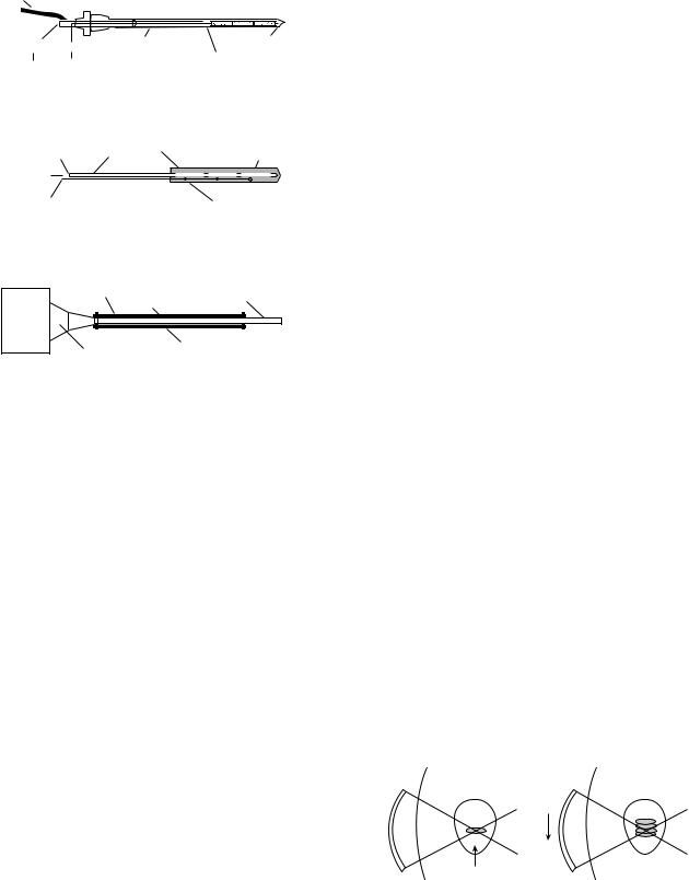
Interstitial techniques are used for treating deep-seated and/or large tumors that are not amenable for surgical resection. Heating sources are implanted into the tumor, thus focusing the energy directly to the site. Interstitial radiation is a standard practice in the treatment of tumors, therefore incorporating adjuvant heat is a logical progression to maximizing treatment. There are three basic designs of interstitial ultrasonic applicators: catheter cooled and direct coupled that consists of tubular piezoceramic transducers, and acoustic waveguide antennas (7) (Figs.16a–c).
Multielement ultrasound applicators with catheter cooling use piezoceramic tubular transducers (1.0–1.5 mm o.d. 10–20 mm long, with frequency ranging from 7 to 10 MHz) have circulating coolant channels incorporated within the support structures to allow the applicator to be sealed in place within closed end implant catheters (13–14 gauge) (7) (Fig. 16a). These catheters are able to improve control of radial penetration of heat. In addition, it has the ability to control longitudinal power deposition along the length of the applicator (7,90–94). The power to each tubular transducer can be adjusted to control tissue temperature along the length of the catheter. The length and the number of transducers can be selected depending on the desired temperature and longitudinal resolution. This feature is very valuable in that it allows adjustability to
tumor geometry variations, blood perfusion variations, and the variation within the tumor tissue. Another advantage of this device is that, unlike microwaves and RF hyperthermia, the power deposition pattern is not limited by the length of insertion or whether other catheters are within the implant. These catheters are more challenging than others for the operator to use skillfully because it is complicated to control both the electronics and the water cooling. Also, small transducers are less reliable. However, it is this complexity that allows for great plasticity in therapeutic temperature distributions (7).
Direct coupled applicators are used to deliver thermobrachy therapy via remote afterloading radiation sources (Fig. 16b). Larger applicator size limits these catheters to few clinical treatments. The implant catheter consists of the transducer and an acoustically compatible housing, which is biologically and electrically insulated. The implant catheter usually ranges from 2.2 to 2.5 mm in diameter. The inner lumen is formed from a catheter that is compatible with standard brachytherapy and commercial after loaders. The transducers have sensors that are able to monitor tissue temperature. In order to conserve size, a water cooling mechanism was not included as part of the catheter. This device is less efficient because transducer self-heating increases the wall temperature and thus reduces radial heating. Therefore, the thermal penetration is sensitive to acoustic frequency (7,95,96). Some studies have shown that integrating an air cooling system to this catheter will allow for better heating penetration (7,95).
The acoustic wave-guide antenna has a minimally invasive 16–24 gauge stainless steel needle that is coupled by a conical tapered velocity transformer to a piezoceramic disk transducer (1.3 cm o.d. operating at 1 MHz) (7,99) (Fig. 16c). The length of the radiating tip can be changed by adjusting the length of the plastic sleeve by 1–1.5 cm. The needle diameter size minutely fluctuates due to Raleigh surface waves propagating from the wave-guide generating flexural vibrations of the needle portion. Acoustic patterns that have been measured demonstrate peaks and nodes in adjacent tissue along the radiating aperture. The temperature of the tissue that is radiated matches the temperature of the radiating antennae. The disadvantages of this system are that the power output is potentially limited for larger or more perfused tumors, and it is difficult to control the longitudinal power deposition (7).
Focused |
|
Focused |
|
ultrasound |
|
ultrasound |
Tissue |
transducer |
Tissue |
transducer |
|
|
|
target |
|
|
target |
|
|
|
|
|
|
Focal |
|
|
Skin |
volume |
B |
Skin |
Figure 17. Schematic of HIFU. (a) Illustrates a formation of a single lesion. (b) Illustrates a confluent array of lesions required for a therapeutic effect. (Published with permission from Ref. 98).
Figure 18. Image of coagulation and liquefied necrosis created with HIFU in an ex vivo porcine kidney. (Published with permission from Ref. 108).
A Brief History of HIFU
Using HIFU as an extracorporeal technique of creating coagulative necrosis was first conceptualized in 1942 by Drs. Lynn and Putnam (12,98,99) (Fig. 17a). In 1954, Dr. William Fry was the first to use HIFU to destroy central nervous tissue in the brains of cats and monkeys (12,98,100,101). Later, Frank Fry treated patients with Parkinson’s disease and neuromata (12,98,102). Throughout the 1950s and 1960s, HIFU research continued, although it was often plagued with limited success due to lack of technology (103–106). In 1956, Dr. Burov suggested that HIFU can be implemented in the treatment of cancer (12,98,107). Since then, the popularity of HIFU has gradually increased with the advent of better devices and with the success of its use in vitro and in vivo experimental trials. In current literature, HIFU is categorized as a high temperature hyperthermia because higher temperatures than those used in conventional hyperthermia are required to achieve therapeutic goals.
BASIC PRINCIPLES OF HIFU
The concept of HIFU is similar to that of using a magnifying glass to focus the sun’s beams to set fire to some dry leaves. Only the leaves that are in focus will be set on fire, the surrounding ones will be spared (12,98). Likewise, if an ultrasonic beam with sufficient energy is tightly focused, it can be used to elevate temperatures within a target tissue resulting in cell death and coagulative necrosis while sparing the skin and surrounding tissues (98,108) (Fig. 18). Histologically, there is a sharp demarcation between the necrotic tissue that was radiated with HIFU and the healthy surrounding tissue. In the liver, 2 h after exposure, the cells look normal, however, approximately a 10 cell wide rim of glycogen poor cells can be found. After 48 h, the entire area that was radiated will be dead (109).
During HIFU procedures, tissue temperature >56 8C are used because at that temperature irreversible cell
HYPERTHERMIA, ULTRASONIC |
75 |
death through coagulative necrosis occurs. The main mechanism used is coagulative necrosis via thermal adsorption (110). The other mechanism is cavitation induced damage that is caused by both thermal and mechanical properties of the ultrasound wave (110,111). However, recent studies have been investigating the use of cavitation to enhance the level of ablation and to reduce exposure times. It has been proposed that a focused ultrasound protocol that induces gas bubbles at the focus will enhance the ultrasound absorption and ultimately create larger lesions (110,112). Individual HIFU exposure times can be as little as 1–3 s, while larger volumes may require up to 30–60 s. Individual lesions can be linearly complied to create a clinically relevant lesion (Fig. 17 b). Since individual exposure time is quick, issues (e.g., the cooling effects of blood perfusion) can be considered negligible (7,98,113,114). Therefore, energy transfer and temperature elevation in tissue is considered proportional to acoustic field energy (100). The lesions are cigar-shaped or ellipsoid with the long axis parallel to the ultrasonic beam (12,98). In order to ablate tissue transducer frequency must be between 0.5 and 10 MHz. The higher the frequency, the narrower and shallower the lesion will be. The wavelength ranges from 3 to 0.25 mm. The size of the focal point is determined by the wavelength. Thus, the transverse diameter of the focus is limited to one wavelength and the axial diameter is eight times that wavelength. As a result of this, all generators create a focal size that is 10 1 mm. The shape of the lesion is determined by the acoustic properties of the tissue, ultrasound intensity in conjunction with exposure time, and transducer geometry (12). Lesion size is determined by power density at the focus, pulse duration, and the number of pulses. In order to create a well-demarcated lesion the intensity must be >100 W cm 2, thus being able to reach temperatures that are >65 8C in <5 s (11). Focal peak intensities generally range between 300 and 2000 W cm 2 (7). The ultrasonic waves used in HIFU are generated by piezoelectric elements. In order to achieve high intensity focus ultrasound that is able to ablate tissues three techniques have been found to focus the ultrasound beam: (1). spherical arrangement of piezoelements (Fig. 19), (2) combination of a plane transducer with an acoustic lens (Fig. 20), (3). cylindrical piezoelementstogetherwithaparabolicreflector(11)(Fig.21).
CURRENT EXTRACORPOREAL DEVICES, INTRACAVITARY DEVICES, AND IMAGING
While there are many devices that are used in experimental trials, few of those are currently used in widespread clinical practice. The two main categories of HIFU devices are extracorporeal and transrectal. Extracorporeal devices have been implemented in experimental trials in many medical fields. Extracorporeal devices use larger transducers, lower frequencies, and longer focal lengths than intracavitary devices (97).
An important factor in clinical application of these devices is the ability to monitor treatment accurately. In current practice, this is accomplished either by using real-time ultrasound (116–118) or MRI (119–122). When
76 HYPERTHERMIA, ULTRASONIC
 Treated volume
Beam path
Transducer
Figure 19. A single spherically curved focused transducer. (Published with permission from Ref. 110).
MR is used to guide HIFU treatments, sublesioning ultrasound exposures are used to identify the target region, local rise in temperatures are used to confirm the position of the ultrasound focus and then higher intensity therapeutic exposures are used for treatment. Currently, several groups are using ultrasound surgery systems that utilize MRI to map temperature elevations online during HIFU procedures (110,120–122). This technique has been used to treat breast tumors and uterine fibroids, and these treatments are in the process of being used clinically in several countries (110,123–125). The MR can effectively use temperature data to determine the parameter of thermal tissue damage (110) and is limited in that it is costly, has lower spin resolution, and because of its technology for producing MR compatible ultrasound equipment required for HIFU is lagging.
When ultrasound is used as a guide, the diagnostic transducer is arranged confocally with the therapeutic transducer and their relationship is fixed. The position
Aluminum lens |
Brass |
|
|
housing |
Water tubing |
||
|
Latex condom |
External view of HIFU |
|
transducer |
Figure 20. A plane transducer with an acoustic lens used for focusing the ultrasound waves. (Published with permission from Ref. 115).
Focal point 32x4mm
Focal distance 100 mm
1 MHz Ultrasound field
Parabolic |
Piezoelectric |
|
cylinder |
||
reflector |
||
|
|
B-mode |
100 mm |
ultrasound probe |
Figure 21. A cylindrical |
transducer with parabolic reflector. |
(Published with permission from Ref. 108).
of the therapeutic focus can be reliably identified on the diagnostic image. The extent of treatment can be monitored by recording post-treatment gray scale changes on the diagnostic image (98). Ultrasound as a guide is advantageous in that it is less expensive and is more readily accessible, it has faster treatment times, compact sized equipment, and provides a good correlation between observed ultrasound changes and the region of necrosis in the tissue. The disadvantage of using ultrasound as a guide is that image quality is not optimal (98,110,126). Furthermore, ultrasound waves are obstructed by bone and air-filled viscera.
MEDICAL APPLICATIONS OF HIFU
Liver Cancer
While hepatocellular carcinoma is frequently encountered in clinical practice, hepatic metastasis from other primary sources is much more common. Currently, the only definite treatment choice for hepatic metastases is surgery, however, 5 year survival rates are only 25–30%. Arterial embolization is another emerging technique. Therefore, the desire to find a noninvasive technique is preeminent (98). The Chongqing HAIFU device has been used for a couple of years in China to treat a variety of tumors, however, adequate data has not yet been collected (98,127,128) (Fig. 22). The JC-HIFU system (HAIFU Technology Company, Chongquing, PR China) uses an extracorporeal transducer that operates at 0.8–1.6 MHz, the aperture 12–15 cm, focal length 9–15 cm. It operates at Isp of 5–15 kW cm 2. A diagnostic ultrasound probe (3.5 MHz) is aligned along the same axis as the therapeutic transducer. Both the treatment and diagnostic transducers are placed in a reservoir of degassed water in the center of the
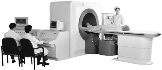
HYPERTHERMIA, ULTRASONIC |
77 |
Figure 22. A Hifu System that is used both clinically and experimentally in the treatment of liver metastates. (Published with permission from Ref. 128).
treatment table. The degassed water provides acoustic coupling between the patient and the transducer. Horizontal movement of the transducer is possible along three orthogonal axes of the bed because it is facilitated by the cylindrical gantry at one end of the table. All movement is controlled by the adjacent computer terminals (128). In a recent clinical trial carried out in Churchill Hospital in Oxford, England in conjunction with Chongqing University of Medical Sciences in Chongqing China, 11 patients with liver metastases were treated with the JC-HIFU device. While it is not possible to have a good statistical analysis with such a small subject pool, some general observations were made about the safety of this device. Of the 11 patients treated, 7 out of 11 patients complained of transient pain and 3 out of 11 complained of superficial burns. Out of the 7 patients that experienced pain, oral analgesia brought relief to 6. Burn sites were treated with ice-packs and aloe gel. Two of the three burn sites were only millimeters across. One of the burns was 2 3 cm and had healed by the 2 week follow-up period. It appears that from a safety standpoint the JC-HIFU is a feasible treatment option for hepatic metastases, however, larger trials will be needed to determine the true efficacy of the treatment (128).
Another study by Wu et al looked at 55 patients with hepatocellular carcinoma with cirrhosis. Tumor size ranged 4–14 cm in size with an average size of 8.14 cm. Patients were classified according to progression of disease: 15 patients had stage II, 16 had stage IIIA, and 24 had stage IIIC. All patients were treated with an extracorporeal HIFU device similar to the one previously mentioned for the treatment of liver metastases. The average number of treatment applications was 1.69. There were no serious side effects. Imaging following HIFU treatment evaluated for the absence of tumor vascular supply and shrinkage of treated lesions. Serum alpha-fetoprotein returned to normal in 34% of patients. At 6 months, 86.1% of the patients were still alive, at 12 months 61.5% of the patients were still alive, and at 18 months 35.3% of the patients were still alive. The survival rates were the highest in patients who were stage
II. Therefore, this study demonstrated that HIFU is a safe option in the treatment of hepatocellular carcinoma (129).
Prostate Cancer
Prostate cancer is one of the common types of cancer in males, and it is frequently the cause of cancer-related death (130). Since physicians are able to detect prostate cancer early, there has been an increase in the number of patients needing treatment. Radical prostatectomy is the treatment of choice in patients who have organ-confined disease and a life expectancy of >10 years. Radical prostectectomy offers excellent results 5 and 10 years after the operation, although there is still risk of morbidity associated with the operation, thus precipitating the need for a noninvasive procedure. Currently, brachytherapy, cryosurgery, 3D conformal radiotherapy, and laparoscopic radical prostatectomy have been implemented with good results (130,131). However, if a cure is not achieved, these treatments cannot be repeated and there is high risk of morbidity associated with salvage radical prostatectomy, thus necessitating the need for another treatment option. In 1995, Madersbacher reported that they were able to destroy the entire tumor within the prostate (98,132). Early reports showed success rates of controlling local tumors at 50% at 8 months and then approaching 90% in later studies (98,133,134). In the later years, as clinicians gained more experience and as technology has improved, treatment of the entire gland was performed (98,135,136).
A recent report was published that looked at 5 year results with transrectal high intensity focused ultrasound in the treatment of localized prostate cancer. One hundred and forty six patients were treated with Ablatherm device (EDAP, Lyon, France). The tablespoon-shaped intracavitary applicator contains both a 7.5 MHz retractable ultrasound scanner for diagnosis and a piezoelectric therapeutic transducer that can be driven at frequencies of 2.25– 3.0 MHz. The computer-controlled treatment head is able
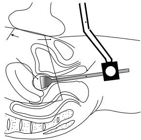
78 HYPERTHERMIA, ULTRASONIC
to move three dimensionally. The applicator can be rotated 45 8 in the rectal ampulla. A cooling device that consists of a balloon containing degassed coupling fluid surrounds the treatment head. Energy can be released from the balloon rectal interface thereby maintaining rectal temperatures <15 8C. Out of 137 patients 6 reported symptomatic UTI, 2 reported chronic pelvic pain, 16 reported infravesicular obstruction, 8 reported grade1 stress incontinence, and 1 reported rectourethral fistula. The success rate of the Ablatherm system is between 56 and 73% (131).
Another study that was published by Uchida et al. performed 28 HIFU treatments on 20 patients to treat localized prostate carcinoma (T1b-2NOMO). A modified Sonoblate 200 HIFU device (Focus Surgery, Indianapolis Ind.) was used in this study. Sonoblate 200 uses a 4 MHz PZT transducer for both imaging and treatment. Each pulse delivery ablates a volume of 2 2 10 mm3 in a single beam with 2.5 and 4.5 cm focal length probes. Probes with focal lengths of 3.0, 3.5, 4.0 cm can be used in a splitbeam conformation to create lesion sizes of 3 3 10 mm3. A cooling device maintains rectal temperatures at <22 8C. In this study, there was a 100% success rate. The UTI-like symptoms were common in the first 2 weeks post-HIFU, but were easily remedied with alpha-blockers and painkillers. One patient had a rectourethral fistula after a second HIFU treatment. Of 10 patients who were still able to attain tumescence prior to the procedure, 3 reported postoperative impotence. It is hypothesized that the reason the Sonoblate 200 is getting superior results to the Ablatherm system is that the treatable focal length is longer in the Sonoblate system. This allows the Sonoblate 200 to treat prostates <50 mL, whereas the Ablatherm can only treat prostates that are <30 mL. However, a controlled prospective study is needed to evaluate the potential reasons for this difference in efficacy (130).
Gynecology
The most common pelvic tumor in women of reproductive age is fibroids. The current surgical options available to manage fibroids are either hysterectomy or myomectomy. Hysterectomy is often not a viable option for women who wish to have children. Myomectomies often result in 50% tumor recurrence in 5 years. Hormone therapy results in temporary reduction in tumor size by 35–65% (115). Therefore, there is a need for a permanent, noninvasive technique to manage fibroids. A device was developed for treating uterine fibroids. The prototypic device aligns a commercial abdominal diagnostic ultrasound transducer with a therapeutic ultrasound intracavitary probe (Fig. 23). This device was constructed to accommodate the specific constraints of the female pelvic anatomy. The transducer contains a 3.5 MHz PZT-8 crystal, 25.4 mm in diameter bonded by an aluminum lens to focus the ultrasound beam. A water-filled latex condom is used for acoustic coupling of the transducer and also has the potential for transducer and tissue cooling. Ergonomics testing in humans demonstrated clear visualization of the HIFU transducer in relation to the uterus, thereby demonstrating a potential for HIFU to treat fibroids from the cervix to the fundus through the width of the uterus. However, this device
|
|
Ultrasound |
|
|
image probe |
|
|
Image |
Water |
|
plane |
|
|
|
filled |
|
|
condom |
Bladder |
|
|
|
|
|
Uterus |
|
Rectum
 Device
Vagina
 Transvaginal
HIFU transducer
Figure 23. Conceptual diagram of the transvaginal device HIFU in use. The dotted line represents the image plane. Three factors determine what area can be treated by the HIFU transducer: focal length, the range of water stand-off, and the range of mobility once inside the vagina. (Published with permission from Ref. 115).
needs to be tested in treating the uterus in large animal models prior to beginning human trials (115). Extracorporeal devices have been used in a small clinical phase I trials, but the results are still pending (98,137).
Breast Cancer
Every year >1 million new cases of breast cancer are diagnosed. Breast cancer is the most common malignancy in women (138,139). In the past, the only options available to women were radical and modified radical mastectomy that included dissection of the axillary lymph nodes. More recently, breast conservation surgery in conjunction with radiotherapy, chemotherapy, and hormone therapy has gained popularity in early stages of breast cancer. However, the change in approach toward a less radical surgery, while being better for a woman’s body image, has not really increased long-term survival rates in breast cancer patients (138,140). Other options, such as cryoablation and laser frequency have been studied as minimally invasive approaches, however, these techniques are limited in that they require percutaneous access and that they are only able to treat small masses. In a recent study by Wu et al., (65) women with breast cancer (T1-2, N0-2, M0) verified with biopsy were studied. Patients were divided into a control group that had a modified radical mastectomy, and a group that had extracorporeal HIFU followed by a radical mastectomy. The HIFU system used is the same one described earlier in the treatment of liver malignancies, the JC-HIFU therapeutic system. The therapeutic U.S. beam was produced by a 12 cm in diameter PZT-4 ceramic transducer with a focal length of 90 mm that was driven at a frequency of 1.6 MHz. The ellipsoid focal region dimensions were 3.3 mm along the beam axis, and 1.1 mm
along the transverse axis. A real-time imaging U.S. device, the AU3 (Esaote, Genoa, Italy) was used at frequencies of 3.5–5.0 MHz. The diagnostic transducer is placed in the center of the therapeutic transducer. Real-time imaging can accomplish three separate tasks. It can locate the tumor that needs to be treated, it can guide the deposition of U.S. energy into the tumor, and it can provide real-time assessment of the coagulation necrosis during therapy. The results demonstrated that there were no severe side effects. Those that were reported included mild local pain, warmth, and a sensation of heaviness in the affected breast. However, only 4 of the 23 HIFU patients had significant pain to require a 3–5 day course of oral analgesics. Only one patient had a minor skin burn. Pathologic examination of the breast tissue revealed complete coagulative necrosis, and the tumor vasculature was damaged. The immunohistological staining revealed that no expression PCNA, MMP-9, and CD44v6 was found, indicating that the tumor cells had lost their ability to proliferate, invade, and metastasize. Therefore, this study demonstrated the safety and efficacy of HIFU in the treatment of breast cancer (138).
Neurology
Recently, there have been some published studies that propose using large array ultrasound transducers to overcome distortions caused by the skull (110). The goal has been to be able to create an array that can focus to destroy target tissue while preserving surrounding tissue. A 320 element array has been used to focus ultrasound through10 human skulls. This approach is completely noninvasive. This technique is modeled after a layered wave vectorfrequency domain-model and uses a hemisphere-shaped transducer to propagate ultrasound through the skull using CT scans as a guide (110,141,142). The ability to focus energy has implications that are not limited to just tumor treatment. It has been shown that focused ultrasound can selectively and consistently open the blood brain barrier (BBB) (110).
Another neurological area that may benefit from HIFU is in the treatment of nerve spasticity and pain. Spasticity, which is signified by uncontrollable muscle contractions, is difficult to treat. In a recent study, HIFU was used to treat and suppress the sciatic nerve complex of rabbits in vivo. An image-guided HIFU device including a 3.2 MHz spherically curved therapeutic transducer and an ultrasound diagnostic device were used. A focal intensity of 1480–1850 W/CM2 was used to create a complete conduction block in the 22 nerve complexes. Treatment times averaged 36 s. Gross histological examination revealed blanched nerve complex with lesion dimensions of 2.8 cm3. Further histological examination revealed the probable cause of nerve block as axonal demyelination and necrosis of Schwann cells. This study illustrates the potential that HIFU may have in the treatment of nerve spasticity (143).
Cardiovascular System
The role of ultrasound in cardiology has been instrumental to the increasing knowledge of the cardiovascular system.
HYPERTHERMIA, ULTRASONIC |
79 |
Diagnostic ultrasound technology has led to a greater understanding of the anatomy and physiology of the human heart and vascular systems. Over the years, in addition to diagnostic use, the role of ultrasound has been expanded to the therapeutic realm. Both conventional ultrasound and HIFU modalities have been used with varied success in many cardiovascular therapeutic applications. These applications range from harvesting the internal mammary artery for coronary artery bypass surgery to ablation of cardiac arrhythmias. An ultrasonically activated (vibrating up to 55,000 Hz) harmonic scalpel (Ethicon Endosurgery, Cincinnati, OH) produces low heat (<100 8C) thereby effectively coagulating and dividing the tissue and has a wide range of applications in cardiothoracic surgery (144). By using a 1 MHz phased array transducer with an acoustic intensity of 1630 W cm 2 or 22547 W cm 2 one can successfully create precise defects ranging from 3 to 4 mm in diameter ex vivo in porcine valve leaflet, canine pericardium, human newborn atrial septum, and right atrial appendage (145). Cardiac arrhythmia is one area where significant work has been done using ultrasonic hyperthermia for therapeutic purposes. Strickberger et al. demonstrated an extracorporeal HIFU ablation of the atrioventricular junction of beating canine heart after thoracotomy (146). Their experimental system consisted of a polyvinyl membrane covering the heart and lungs. The thoracic cavity was filled with degassed water serving as a coupling medium. A 7.0 MHz diagnostic 2D ultrasound (Diasonics VST Master Series, Diasonics/Vingmed Ultrasound Inc) attached to a spherically focused single piezo-
electric |
element therapeutic |
ultrasound |
transducer |
|
(1.4 MHz |
frequency; |
1.1 8.3 mm focal |
length and |
|
63.5 cm |
focal zone) |
with the |
maximum |
intensity of |
2.8 kW cm 2 was applied during the diastole for 30 s to achieve complete AV nodal junctional block (Fig. 24a–c). Experience with HIFU application is very preliminary and has not been tried for AV nodal ablation in humans yet.
Ultrasound had also been used clinically in the treatment of atrial fibrillation (AF), which is the most common arrhythmia affecting 0.5–2.5% of the population globally. Over the last decade, ablation procedures by isolating the pulmonary veins and eliminating electrical triggers from the atria has become a popular and effective mode of therapy for AF. Traditionally, RF energy has been used as an energy source for ablation. Radio frequency catheter ablation of AF requires good tissue contact, multiple lesions, significant experience and manual skills with long procedure time. Complications related to RF application in AF ablation include pulmonary vein stenosis, atrioesophageal fistula, left atrial rupture due catheter perforation or inappropriate amount of power. The limitations of the existing RF technology could be overcome with the use of HIFU balloon systems (147).
Our group performed the initial work on pulmonary vein isolation in humans using a through-the-balloon circumferential ultrasound (conventional-unfocused) ablation system for treatment of recurrent atrial fibrillation (148). Fifteen patients with drug refractory atrial fibrillation underwent a PVI using a novel transballoon ultrasound ablation catheter (Atronix, Inc) (Fig. 25a–c). The ablation system was composed of a 0.035 in. diameter
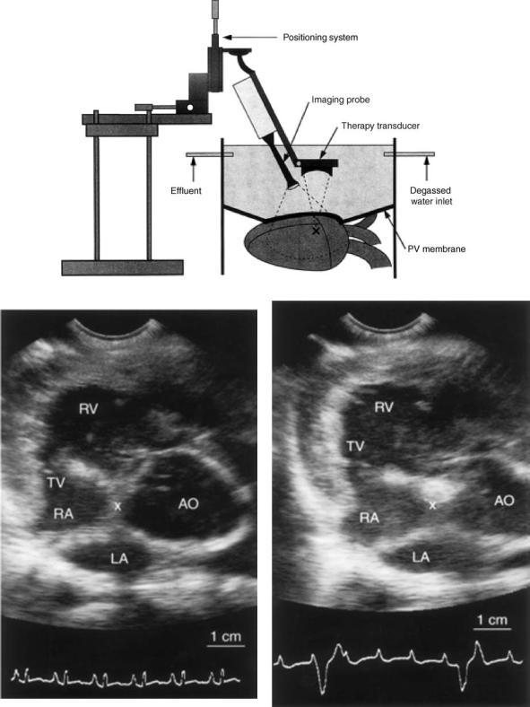
80 HYPERTHERMIA, ULTRASONIC
Figure 24. (a) Schematic of the experimental HIFU apparatus. The therapeutic ultrasound transducer is mounted 63.5 mm from the target (X). A polyvinyl chloride membrane covers the heart and the lungs. Degassed water flows in and out of the thoracic cavity at a rate of 600 mL min 1. Combined diagnostic/ablation transducers are placed into degassed water. (Published with permission from Ref. 146). (b) ECG and Echocardiogram of a canine heart. Prior to ablation of the AV node. (c) After ablation of the AV node using HIFU, the ECG shows complete AV block and the echo image depicts an increased density of the ablated tissue. (Published with permission from Ref. 146).
Figure 25. Anatomical pulmonary vein variations and technical limitations. (Published with permission from Refs. 148 and 149).
luminal catheter with a distal balloon (2.2 cm at maximum diameter) housing a centrally located ultrasound transducer (8 MHz). The ultrasound ablation system was advanced over a guide wire (0.035 in., 0.088 cm) to the intended pulmonary vein. The ablation performance and tissue temperature are monitored by thermocouples on the balloon and the therapeutic transducer. The ablation time was 2 min with an additional minute to deflate the balloon. The energy was delivered perpendicularly to the surface of the balloon and ablation at the funnel portion of the pulmonary vein (antrum) could not be achieved with the original design. Additionally, other anatomical characteristics of the target sites like ostial diameter larger than the balloon size, inability to reach the right inferior or other pulmonary vein ostia, ostial instability, early branching of the vein, and eccentric position of the ultrasound transducer in the vein made it difficult to deliver energy effectively (Fig. 26). These technical limitations have been addressed in some of the newer balloon systems where the energy delivery could be accomplished in a divergent angle enabling ablation around the antrum with the tip of the balloon sitting at the pulmonary vein ostium. Early animal studies on HIFU mediated AF ablation have shown promising results with an experimental device that focuses ultrasonic energy via a parabolic balloon, using gas or fluid as a reflector (ProRhythm INC.) (Fig. 25c–e). (149,150).
Since 2003 60 patients were treated using this system. With improved catheter design the success rate of AF ablation has increased from 50 up to 80% without evidence of pulmonary vein stenosis. These preliminary human study results need to be confirmed in larger series. Since there are no large clinical trials on AF ablation with this technology, it is still somewhat premature to predict if HIFU is the complete answer. This device is expected to be released in Europe in 2005 (149,150).
Attempts have been made to harness HIFU for transmyocardial revascularization (TMR) to improve blood supply to damaged myocardium caused by advanced heart disease. Using a 10 cm diameter transducer operating a frequency of 2.52 MHz, intensity of 2300 W cm 2 and pulse repetition period of 40 ms at 50% duty cycle, small chan-
HYPERTHERMIA, ULTRASONIC |
81 |
nels were successfully created in canine myocardium (151). This shows the potential for future application for HIFU in TMR in a noninvasive fashion.
Other Applications of HIFU
Several branches of medicine have already begun to benefit from the use of HIFU with the prospect of many more applications in the future. Thus far the greatest influence of HIFU has been in oncology, with other fields now exploring and experimenting with HIFU to determine its potential utility. The HIFU has been proposed as a tool for synovectomy in the treatment of rheumatoid arthritis (RA) (98,152) and has been used to control opiate refractory pain in pancreatic cancer patients (98,127) and internal bleeding in organs and vessels (98,153). A hand-held HIFU device has been successfully used to perform vasectomies in dogs as a 1–2 min procedure (98,154).
Future Perspectives in Conventional Hyperthermia
and HIFU Use
Heat as therapeutic entity has had a rich history punctuated with many successes and failures. The evolution and integration of therapeutic hyperthermia in the clinical setting have been the product of clinical trials, development of new devices, and education of the medical personnel. Conventional hyperthermia has been used for a long time with many energy sources such as electromagnetic, ultrasound, and microwaves. Similarly, it has been >50 years since HIFU was first conceptualized and actualized. Many subspecialties of medicine have benefitted from the use of hyperthermia. Some of the limitations that were miring conventional hyperthermia and HIFU have only recently begun to be overcome and now these therapies can reach a wider patient population. Both of these techniques share similar obstacles due to the limitations that are inherent to ultrasound. Indeed, ultrasound hyperthermia procedures are limited in that ultrasound cannot propagate through air-filled cavities (e.g., lung or bowel). Consequently, lung tumors other than those that are at the periphery are not likely to be amenable to treatment with HIFU or conventional hyperthermia. Also, tumors that are in close proximity to the bowel or within the bowel wall pose an increased chance of visceral perforation with HIFU use. In addition, other side effects such as pain, soft tissue and bone damage, and skin burns have been reported. Often these side effects can be minimized by varying scan paths, altering frequency, power deposition, or the applicator position (7). The success of both hyperthermia techniques is determined by whether ultrasound energy can be properly directed to the site of interest, or if therapeutic temperatures are achieved, and if other factors can be compensated for, such as hemodynamic changes. Other challenges facing ultrasound hyperthermia systems include the ability to gain control over spatial distribution of heat, tissue temperature monitoring, and improved diagnostic visualizations in order to better treat the tumor site. The HIFU treatment times also need to be shortened. Despite this, treatment times of 1 h for a 2 cm superficial tumor using HIFU is preferable to surgical resection; conversely, at present the same tumor can be treated much
82 HYPERTHERMIA, ULTRASONIC
Figure 26. (a) A schematic of the first ultrasound balloon system illustrating the radial delivery of ultrasound energy that is transferred perpendicularly to the tissue. (b) 8F transballoon ultrasound ablation catheter witha central lumen that can accommodate a 0.035 in. guidewire.The distalend ofthe catheter lodges a cylindrical transducer axially with a saline-filled balloon inflated over it. (c) The balloon is advanced over a guidewire at the ostium of the left upper pulmonary vein. An occlusive pulmonary venogram is done to confirm that the transducer is located at the proximal portion of the vein. Published with permission from Refs. 148 and 149. (d) A schematic of the HIFU device illustrating a ring pattern of ultrasound transmission. The parabolic balloon focuses the ultrasound beam forward. The HIFU catheter is able to create lesions in the antrum away from the lumen of the pulmonary veins thus reducing the likelihood of pulmonary vein stenosis. (e) The HIFU catheter at the ostium of the pulmonary vein.
more quickly with radiofrequency ablation. However, in large tumors longer treatment times are justified because there are very low mortality and morbidity rates associated with the use of HIFU (98).
The benefits of both conventional hyperthermia and HIFU are limitless, but both need more testing in larger patient populations to fully delineate their clinical role. At present, the scarcity of available equipment, the required technical expertise and the lack of thoroughly trained providers, the increased complexity and difficulty involved in using conventional hyperthermia and HIFU when compared to other systems (e.g., electromagnetic) have limited the widespread use of this treatment modality
(7). Issues, such as accurate delivery of focused ultrasound to the target tissue, the ability to monitor and control temperatures, and reasonable treatment times, have all been improved upon and will continue to be refined with further testing and research. Imaging modalities like MRI and high resolution CT scan will enhance the precision of HIFU in various system applications. In the future, HIFU could emerge as a good alternative to traditional surgery, and conventional hyperthermia may become a mainstay as an adjunct to chemotherapy and radiation to ultimately improve the arsenal of methodologies available to better treat patients.
BIBLIOGRAPHY
1.Seegenschmiedt MH, Vernon CC. A historical perspective on hyperthermia in oncology. In: Seegenschmiedt MH, Fessenden P, Vernon CC, editors. Thermoradiotherapy and Thermochemotherapy Vol 1. Berlin: Springer Verlag; 1995. pp 3–44.
2.Modern cancer treatment by oncothermia and hyperthermia. 2003. Available at http://www.hot-oncotherm.com/historical. htm. Accessed 2005, Feb 4.
3.Lele P. Hyperthermia Ultrasonics. Encyclopedia of Medical Devices. New York: John Wiley, Sons; 1998.
4.History of Hyperthermia. Available at http://www.starfarm.it/ hyperthermia/history.htm. Accessed 2005, April 4.
5.van der Zee J. Heating the patient: A promising approach? Ann Oncol 2002;13:1173–1184.
6.Fesseden P, Hand JW. Hyperthermia therapy physics. In: Smith AR, editor. Medical radiology: Radiation therapy physics. Berlin: Springer Verlag; 1995. pp 315–363.
7.Diederich CJ, Hynynen K. Ultrasound technology for hyperthermia. Ultrasound Med Biol 1999;25:871–887.
8.Bushberg J, Seibert J, Leidholdt E, Boone J. The Essential Physics of Medical Imaging. Philadelphia Lippincott, Williams, and Wilkins; 2002. pp 469–553.
9.Chapelon JY, et al. New Piezoelectric transducers for therapeutic ultrasound. Ultrasound Med. Biol. 2000;26:153–159.
10.Moros E, et al. Thermal contribution of compact bone to intervening tissue-like media exposed to planar ultrasound. Phys Med Biol 2004; 869–886.
11.Madersbacher S, Marberger M. High-energy shockwaves and extracorporeal high-intensity focused ultrasound. J Endourol 2003;17:667–672.
12.ter Haar G. High intensity focused ultrasound for the treatment of tumors. Echocardiography 2001;18:317–321.
13.Novak P, et al. SURLAS: A new clinical grade ultrasound system for sequential or concomitant thermoradiotherapy of superficial tumors: Applicator description.
HYPERTHERMIA, ULTRASONIC |
83 |
14.Reinhold H, Endrich B. Tumour microcirculation as a target for hyperthermia. Int J Hypertherma 1986;2:111–137.
15.Vaupel PW, Kelleher DK. Metabolic status and reaction to heat of normal and tumor tissue. In: Seegenschmiedt MH, Fessenden P, Vernon CC. editors. Thermoradiation and Thermochemotherapy, Vol. 1. Berlin: Springer Verlag; 1995. pp 157–176.
16.Raaphorst GP. Fundamental aspects of hyperthermic biology. In: Field SB, Hand JW, editors. An Introduction to the Practical Aspects of Clinical Hyperthermia. London: Taylor and Francis; 1990. pp 10–54.
17.Fajardo LF, Pathological effects of Hyperthermia in normal tissue. Cancer Res 1984;44:4826s–4835s.
18.Sminia P, et al. Effects of hyperthermia on the central nervous system: A review. Int J Hyperthermia 1994;10:1–130.
19.Wondergem J, et al. Effects of local hyperthermia on the motor function of the rat sciatic nerve. Int J Rad Bio 1988;53:429–439.
20.Falk MH, Issels RD. Hyperthermia in oncology. Int J Hyperthermia 2001;17:1–18.
21.Overgaard J, et al. Randomised trial of hyperthermia as adjuvant to radiotherapy for recurrent or metastatic malignant melanoma. The Lancet 1995;345:540–543.
22.Sneed PK, et al. Survival benefit of hyperthermia in a prospective randomized trial of brachytherapy boost (hyperthermia for glioblastoma multiforme). Int J Rad Oncol Biol Phys 1998;40:287–295.
23.Vernon CC, et al. Radiotherapy with or without hyperthermia in the treatment of superficial localized breast cancer: Results from five randomized controlled trials. Int J Rad Oncol Biol Phys 1996;35:713–744.
24.Valdagni R, Amichetti M, Pani G. Radical Radiation alone versus radical radiation plus microwave hyperthermia for N3 (TNM-UICC) neck nodes: A prospective randomized clinical trial. Int J Rad Oncol Biol Phys 1988;15:13–24.
25.Datta N, et al. Head and Neck cancers: Results of thermoradiotherapy versus radiotherapy. Int J Hyperthermia 1990;6:479–486.
26.Perez et al. Randomised phase III study comparing irradiation and hyperthermia with irradiation alone in superficial measurable tumors. Am J Clin Oncol 1991;14:133–141.
27.Jones E, et al. Randomized Trial of Hyperthermia and radiation for superficial tumors. J Clin Oncol 2005;23(13):3079–3085.
28.Emami B, et al. Phase III study of interstitial thermoradiotherapy compared with interstitial radiotherapy alone in the treatment of recurrent or persistent human tumors: A prospectively controlled randomized study by the radiation therapy oncology group. Int J Rad Oncol Biol Phys 1996;34:1097–1104.
29.Harima Y, et al. A randomized clinical trial of radiation therapy versus thermoradiotherapy in stage IIIB cervical carcinoma. Int J Hyperthermia 2001;17(2):97–105.
30.Vasanthan A, et al. Regional hyperthermia combined with radiotherapy for uterine cervical cancers: A multi-institutional prospective randomized trial of international atomic energy agency. Int J Rad Oncol Biol Phys 2005;61(1):145–153.
31.Van der Zee J, et al. Comparison of radiotherapy alone with radiotherapy plus hyperthermia in locally advanced pelvic tumors: a prospective, randomized, multicentre trial. Dutch Deep Heat Hyperthermic Group. Lancet 2000; 1119–1125.
32.Perez CA, Gillespie B, et al. Quality assurance problems in clinical hyperthermia and their impact on therapeutic outcome: a report by the radiation oncology group. International Journal of Radiation Oncology, Biology, and Physics, 16:551–558.
33.Voldagni R, Amichetti M. 1994 Report of long-term follow-up in a randomized trial comparing radiation therapy plus hyperthermia to metastatic lymphnodes in stage IV head and neck patients. International Journal of Radiation Oncology, Biology, and Physics, 28:163–169.
84 HYPERTHERMIA, ULTRASONIC
34.Dahl O. Interaction of heat and drugs in vitro and in vivo. In: Seegenschmiedt MH, Fessenden P, Vernon CC, editors. Thermoradiotherapy and Thermochemotherapy, Vol 1. Berlin: Springer Verlag; 1995. pp 103–121.
35.Westermann AM, Grosen EA, et al. A pilot study of whole body hyperthermia and carboplatin in platinum-resistant ovarian cancer. Eur J Cancer 2001;37:1111–1117.
36.Li DJ, Hou BS. A preliminary report on the treatment of esophageal cancer by intraluminal microwave hyperthermia and chemotherapy. Cancer Treatment Reports 1987;71: 1013– 1019.
37.Sugemachi K, et al. Chemotherapy combined with or without hyperthermia for patients with oesophageal carcinoma: a prospective randomized trial. International Journal of Hyperthermia 10:485–493.
38.Kakehi M, et al. Multi-institutional clinical studies on hyperthermia combined with radiotherapy or chemotherapy in advanced cancer of deep-seated organs. International Journal of Hyperthermia 6:719–740.
39.Falk RE, et al. Combination therapy for resectable and unresectable adenocarcinoma of the pancres. Cancer 57: 685–688.
40.Issels RD, et al. Ifosfamide plus etoposide combined with regional hyperthermia in patients with locally advanced sarcomas: a phase II study. Journal of Clinical Oncology 1990;8:1818–1829.
41.Issels RD, et al. Improvement of local control by regional hyperthermia combined with systemic chemotherapy(ifosfamide plus etoposide) in advanced sarcomas: updated report on 65 patients. Journal of Cancer Research and Clinical Oncology 1991;117:141–147.
42.Issels RD, et al. Preoperative systemic etoposide/ifosfamide/ doxorubicin chemotherapy combined with regional hyperthermia in high-risk sarcoma: a pilot study. Cancer Chemotherapy and Pharmacology 1993;31(suppl. 2) S233–S237.
43.Issels RD, et al. Neoadjuvant chemotherapy combined with regional hyperthermia (RHT) followed by surgery and radiation in primary and recurrent high-risk soft-tissue sarcomas (HR-STS) of adults (updated report). Journal of Cancer Research and Clinical Oncology 1998;124(suppl.) R105.
44.Issels RD. Soft Tissues Sarcomas-What is Currently Being Done. European Journal of Surgical Oncology 21(suppl) 471– 474.
45.Eggermont A MM, et al. Isolated Limb Perfusion with highDose tumor necrosis factor alpha in combination with interferon gamma and melphalan for nonresectable extremity soft tissue sarcomas: a multicenter trial. Journal of Clinical Oncology 14:2653–2665.
46.Wiedemann GJ, et al. Ifosfamide and carboplatin combined with 41.8 8C whole body hyperthermia in patients with refractory sarcoma and malignant teratoma. Cancer Research 54:5346–5350.
47.Weidemann GJ, et al. Ifosfamide carboplantin, and etopside (ICE) combined with 41.8 8C whole-body hyperthermia in patients with refractory sarcoma. European Journal of Cancer 32A:888-891.
48.Robins HI, et al. Phase I Clinical Trail of Melphalan and 41.8 8C whole-body hyperthermia in cancer patients. Journal of Clinical Oncology 1993;15:154–164.
49.Romanowski R, Schott C. Regionale hyperthermie mit systemischer Chemotherapie bei Kindern und Jugendlichen: Durchfuhrbarkeit und Klinische Verlaufe bei 34 intensiv vorbehandelten Patienten mit prognostisch ungunstigen Tumorerkrankkungen. Klinische Padiatrie 205:249–256.
50.Wessalowski R, Kruck H. Hyperthermia for the treatment of patients with malignant germ cell tumors. A phase I/II study
in ten children and adolescents with recurrent or refractory tumors. Cancer 82:793–800.
51.Rietbroek RC, Schilthuis MS. Phase II trial of weekly locoregional hyperthermia and cisplantin in patients with previously irridated recurrent carcinoma of the uterine cervix. Cancer 1997;79:935–942.
52.Takahashi M, Fujimot S. Clinical outcome of intraoperative pelvic hyperthermochemotherapy for patients with Dukes’ C rectal cancer. International Journal of Hyperthermia 10:749– 754.
53.Westermann AM, Wiedemann GJ. A Systemic Hyperthermia Oncologic Working Group trial. Ifosfamide, carboplatin, and etoposide combined with 41.8 degrees C whole-body hyperthermia for metastatic soft tissue sarcoma. Oncology. 2003;64(4):312–21.
54.Anhalt DP, Hynynen K, Roemer RB. Patterns of changes of tumour temperatures during clinical hyperthermia: Implications for treatment planning, evaluation and control. Int J Hyperthermia 1995;11:425–436.
55.Corry PM, Barlogie B, Tilchen EJ, Armour EP. Ultrasound induced hyperthermia or the treatment of human superficial tumors. Int J Rad Oncol Biol Phys 1982;8:1225–1229.
56.Corry PM, et al. Combined ultrasound and radiation therapy treatment of human superficial tumors. Radiology 1982b;145: 165–169.
57.Harrison GH. Ultrasound hyperthermia applicators: Intensity distributions and quality assurances. Int J Hyperthermia 1990;6:169–174.
58.Marmor JB, Hahn GM. Ultrasound heating in previously irradiated sites. Int J Rad Oncol Biol Phys 1978;4:1029– 1032.
59.Marmor JB, Hahn GM. Combined radiation and hyperthermia in superficial human tumors. Cancer 1980;46:1986–1991.
60.Marmor JB, Pounds D, Hahn GM. Clinical studies with ultrasound induced hyperthermia. Natl Cancer Inst Monogram 1982;61:333–337.
61.Marmor JB, Pounds D, Hahn GM. Treatment of superficial human neoplasms by local hyperthermia induced by ultrasound. Cancer 1979;43:188–197.
62.Labthermics Technologies Online.1998–1999. Available at http://www.labthermics.com/hyper.html. Accessed 2005 Jan 26.
63.Anhalt DP, et al. Scanned ultrasound hyperthermia for treat-
ing superficial disease. Hyperthermic oncology. vol 2. Proceedings of the 6th international Congress on Hyperthermic Oncology, Tucson, (AZ); 1992. p 191-192.
64.Lele PP. Advanced ultrasonic techniques for local tumor hyperthermia. Radiol Clin N Am 1989;27:559–575.
65.Harari PM, et al. Development of scanned focused ultrasound hyperthermia: clinical response evaluation. Int J Rad Oncol Biol Phys 1991;21:831–840.
66.Hand JW, Vernon CC, Prior MV. Early experience of a commercial scanned focused ultrasound hyperthermia system. Int J Hyperthermia 1992;8:587–607.
67.Guthkelch AN, et al. Treatment of malignant brain tumors with focused ultrasound hyperthermia and radiation: Results of a phase I trial. J Neuro Oncol 1991;10:271–284.
68.Duthkelch et al.
69.Formine et al.
70.Straube WL, et al. An ultrasound system for simultaneous ultrasound hyperthermia and photon beam irradiation. Int J Rad Oncol Biol Phys 1996;36:1189–1200.
71.Lu XQ, et al. Design of an ultrasonic therapy system for breast cancer treatment. Int J Hyperthermia 1996;12:375–399.
72.Moros EG, Fan X, Straube WL. An investigation of penetration depth control using parallel opposed ultrasound hyperthermia. J Accoust Soc Am 1997;101:1734–1741.
73.Moros EG, Fan X, Straube WL, Myerson RJ. Numerical and in vitro evaluation of temperature fluctuations during reflected-scanned planar ultrasound hyperthermia. Int J Hyperthermia 1998;14:367–382.
74.Moros EG, Myerson RJ, Straube WL. Aperture size to therapeutic volume relation for a multi-element ultrasound system: Determination of applicator adequacy for superficial hyperthermia. Med Phys 1993;20:1399–1409.
75.Moros EG, Roemer RB, Hynynen K. Simulations of scanned focused ultrasound hyperthermia. The effects of scanning speed and pattern on the temperature fluctuations at focal depth. IEEE Trans Ultrason Ferroelec Frequency Control 1988;35:552–560.
76.Moros EG, et al. Simultaneous delivery of electronic beam therapy and ultrasound hyperthermia using scanning reflectors: a feasibility study. Int J Rad Oncol Biol Phys 1995;31: 893– 904.
77.Moros EG, Straube WL, Myerson RJ. Potential for power deposition conformability using reflected-scanned planar ultrasound. Int J Hyperthermia 1996;12:723–736.
78.Lele PP, Parker KJ. Temperature distributions in tissues during local hyperthermia by stationary or steered beams of unfocused or focused ultrasound. Br J Cancer 1982;45 (Suppl):108–121.
79.Hynynen K, et al. A scanned, focused, multiple transducer ultrasonic system for localized hyperthermia treatments. Int J Hyperthermia 1987;3:21–35.
80.Lin W, Roemer RB, Hynynen K. Theoretical and experimental evaluation of a temperature controller for scanned focused ultrasound hyperthermia. Med Phys 1990;17:615–625.
81.Ibbini MS, Cain CA. The concentric-ring array for ultrasound hyperthermia: combined mechanical and electrical scanning. Int J Hyperthermia 1990;6:401–419.
82.Umemura S, Cain CA. The sector-vortex phased array: acoustic field synthesis for hyperthermia. IEEE Trans Ultraon Ferroelec Frequency Control 1989;36:249–257.
83.Ebbini ES, Cain CA. Experimental evaluation of a prototype cylindrical section ultrasound hyperthermia phased array applicator. IEEE Trans Ultrason Ferroelec Frequency Control 1991a;38:510–520.
84.Ebbini ES, Cain CA. A spherical-section ultrasound phased array applicator for deep localized hyperthermia. IEEE Trans Biomed Eng 1991b;38:634–643.
85.Benkeser PJ, Frizzell LA, Goss SA, Cain CA. Analysis of a multielement ultrasound hyperthermia applicator. IEEE Trans Ultrason Ferroelec Frequency Control 1989;36:319– 325.
86.Diederich CJ, Hynynen K. Induction of hyperthermia using an intracavitary ultrasonic applicator. IEEE Ultrason Sympos Proc 1987;2:871–874.
87.Diederich CJ, Hynynen K. Induction of hyperthermia using an intracavitary multielement ultrasonic applicator. IEEE Trans Biomed Eng 1989;36:432–438.
88.Diederich CJ, Hynynen K. The development of intracavitary ultrasonic applicators for hyperthermia: A design and experimental study. Med Phys 1990;17:626–634.
89.Smith NB, Buchanan MT, Hynynen K. Transrectal ultrasound applicator for prostate heating monitored using MRI thermometry. Int J Rada Oncl Biol Phys 1999;33:217–225.
90.Diederich CJ. Ultrasound applicators with integrated cathetercooling for interstitial hyperthermia: Theory and preliminary experiments. Int J Hyperthermia 1996;12:279–297.
91.Diederich CJ, Hynynen K. Ultrasound technology for interstitial hyperthermia. In: Seegenschmiedt MH, Sauer R, editors. Interstitial and intracavitary thermoradiotherapy. Berlin: Springer-Verlag; 1993. pp 55–61.
HYPERTHERMIA, ULTRASONIC |
85 |
92.Hynynen K. The feasibility of interstitial ultrasound hyperthermia. Med Phys 1992;19:979–987.
93.Hynynen K, Davis KL. Small cylindrical ultrasound sources for induction of hyperthermia via body cavities or interstitial implants. Int J Hyperthermia 1993;9:263–274.
94.Lee RJ, Klein LJ, Hynynen K. A multi-element and multicatheter ultrasound system for interstitial hyperthermia. IEEE Trans Biomed Eng 1999.
95.Deardorff DL, Diederich CJ, Nau WH. Air-cooling of directcoupled ultrasound for interstitial hyperthermia and thermal coagulation. Med Phys 1998;25:2400–2409.
96.Diederich CJ, et al. Direct coupled interstitial ultrasound applicators for simultaneous thermobrachytherapy: A feasibility study. Int J Hyperthermia 1996;12:401–419.
97.Jarosz BJ. Feasibility of ultrasound hyperthermia with waveguide interstitial applicator. IEEE Trans Biomed Eng 1996;6:1106–1115.
98.Kennedy J, et al. High intensity ultrasound: Surgery of the future? Br J Rad 2003;76:590–599.
99.Lynn JG, Zwemer RL, Chick AJ, Miller AG. A new method for generation and use of focused ultrasound in experimental biology. J Gen Physiol 1942;26:179–193.
100.Fry WJ, et al. Ultrasonic lesions in the mammalian central nervous system. Science 1955;122:517–518.
101.Fry WJ, Mosberg WH, Barnard JW, Fry FJ. Production of focal destructive lesions in the central nervous system with ultrasound. J Neurosurg 1954;11:471–478.
102.Fry FJ. Precision high-intensity focusing ultrasonic machines for surgery. Am J Phys Med 1958;37:152–156.
103.Ballantine HT, Bell E, Manlapaz J. Progress and problems in the neurological application of focused ultrasound. J Neurosurg. 1960;17:858–876.
104.Warwick R, Pond JB. Trackless lesions in nervous tissues produced by HIFU (high-intensity mechanical waves). J Anat 1968;102:387–405.
105.Lele PP. Concurrent detection of the production of ultrasonic lesions. Med Biol Eng 1966;4;451–456.
106.Lele PP. Production of deep focal lesions by focused ultra- sound-current status. Ultrasonics 1967;5:105–112.
107.Burov AK. High-intensity ultrasonic vibrations for action on animal and human malignant tumours. Dokl Akad Nauk SSSR 1956;106:239–241.
108.Kohrmann KU, et al. Technical characterization of an ultrasound source for noninvasive thermoablation by high-inten- sity focused ultrasound. BJU Int 2002;90:248–252.
109.ter Haar G. Robertson D: Tissue destruction with focused ultrasound in vivo. Eur Urol 1993;23(Suppl. 1):8–11.
110.Clement GT, Perspectives in clinical uses of high-intensity focused ultrasound. Ultrasonics 2004;42:1087–1093.
111.Holt RG, Roy RA, Edson PA, Yang X. Bubbles and HIFU: the good, the bad, and the ugly. In: Andrew MA, Crum LA, Vaezy S, editors. Proceedings of the 2nd International Symposium on Therapeutic Ultrasound; 2002. pp 120–131.
112.Sokka SD, King R, Hynynen K. MRI-guided gas bubble enhanced ultrasound heating in in vivo rabbit thigh. Phys Med Biol 2003;48:223–241.
113.Billard BE, Hynynen K, Roemer RB. Effects of physical parameters on high temperature ultrasound hyperthermia. Ultrasound Med Biol 1990;16:409–420.
114.Kolios MC, Sherar MD, Hunt JW. Blood Flow cooling and Ultrasonic lesion formation. Med Phys 1996;23:1287–1298.
115.Chan A, et al. An image-guided high intensity focused ultrasound device for uterine fibroids treatment. Med Phys 2002;29:2611–2620. Otsuka R, et al. In vitro ablation of cardiac valves using high intensity focused ultrasound. Ultrasound Med Biol 2005;31:109–114.