


H
continued
HYDROCEPHALUS, TOOLS FOR DIAGNOSIS AND TREATMENT OF
SANDEEP SOOD
ANDERS EKLUND
NOAM ALPERIN
University of Illinois at Chicago
Chicago, Illinois
INTRODUCTION
Epidemiology
A congenital form of hydrocephalus occurs in roughly 50 in 100,000 live births (6). Hydrocephalus may also be acquired later in life as a result of a brain tumor, following meningitis, trauma, or intracranial hemorrhage. It has been estimated that prevalence of shunted hydrocephalus is about 40/100,000 population in the United States (7). Untreated hydrocephalus has a poor natural history with a mortality rate of 20–25% and results in severe physical and mental disabilities in survivors (8,9). There has been a significant reduction in mortality and morbidity with use of shunting. However, shunting is associated with a high failure rate; a 40% failure rate occurs within the first year after shunting (10). Advances in the technology have lead to the development of a diverse type of shunt systems to circumvent problems related to long-term shunting, such as obstruction, infection, and overdrainage. Yet, studies done to evaluate these devices have not shown a significant longor short-term benefit from their use compared with the conventional devices (10). It is estimated that, during the year 2000, the cost associated with shunting exceeded one billion dollars in the United States alone (11). Shunt replacement accounted for 43% of shunt procedures. Endoscopic surgery has provided an alternative strategy in patients with obstructive hydrocephalus. However, limited data in the literature suggest that long-term survival of third ventriculostomy is not significantly superior to that of a shunt (12).
Physiology
The CSF flow in the craniospinal system is influenced by two separate processes: (1) the circulation of the CSF from its formation sites to its absorption sites (i.e., bulk flow) and (2) an oscillatory (back and forth) flow during the cardiac cycle (pulsatile flow). The first process governs the overall volume of CSF and thereby influences intracranial pressure (ICP). The second process, the oscillatory movement of the CSF within the craniospinal compartments, is caused by the pulsatile blood flow entering and leaving the intracranial compartment during the cardiac cycle. These two processes occur over different time scales; circulation and replenishing of CSF occurs over minutes, whereas the time scale of the pulsatile CSF flow is milliseconds.
CSF Circulation. Unlike other organ systems, the brain and the spinal cord are unique in being bathed in a clear fluid called cerebrospinal fluid. The exact role that it plays in maintaining the necessary environment for the functioning of the nervous system is unclear. It has been ascribed a role in providing nutrition, removing excess waste, circulating neurotransmitters, maintaining the necessary electrolyte environment, and acting as a shock absorber against trauma.
The distribution of nutrients, or neurotransmitters, and removal of waste products of metabolism, is an unlikely function of CSF, because these chemicals are present in very low concentrations in the CSF. The main function of CSF is to provide buoyancy to support the brain and act as a cushion against trauma. The normal brain weighs about 1500 g; however, supported by the buoyancy of the CSF, its apparent weight is reduced to about 50 g in the cranium. Support for its role in cushioning the brain and spinal cord against trauma comes from clinical conditions like severe spinal canal stenosis. The CSF cushion around at the site of stenosis is markedly reduced. As a result, spinal cord injury often occurs even with minor trauma as the shock waves are directly transmitted from the bone to the spinal cord.
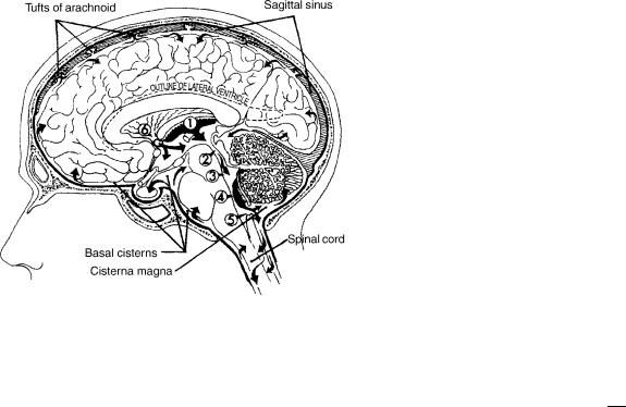
Cerebrospinal fluid is made through a complex process that occurs in the cells of the choroid plexus, which lines the margin of the four fluid-filled spaces in the brain called the ventricles. First, an ultrafilterate of plasma is formed in the connective tissue surrounding the choroidal capillaries. Next, this is converted into a secretion by carbonic anhydrase enzyme present in the choroids epithelium. The CSF is made at a fairly constant rate of about 10 mL/h. Most of the CSF is made in the choroids plexus of the lateral ventricles. Roughly, 20% of the CSF comes from the ventricular walls. As most CSF is made in the lateral ventricles, it is traditionally believed that the CSF bulk flow occurs from the lateral ventricles to the third ventricle, fourth ventricle, and then through the foramen of Magendie and Lushka into the cerebello-pontine cistern and on to the surface of the brain and spinal cord (Fig. 1). A fifth of the CSF runs down around the spinal cord and then back to the cranial subarachnoid space.
The CSF is absorbed by the cells of the arachnoid granulations (13). These are present in the superior sagittal sinus. The process involves pinocytosis of a small quanta of CSF, on the subarachnoid side of the granulations, and discharge into the blood on the venous side. The process is driven by a pressure difference of at least 5 mm Hg between the subarachnoid CSF and the superior sagittal sinus. A small proportion of CSF is also absorbed along the perivascular spaces and along the nerve sheaths exiting the spinal canal (14).
This traditional view has been recently challenged. Johnston et al. in experimental and cadaveric studies have demonstrated that a large amount of CSF is present around the olfactory nerve and the cribriform plate area
1
2 HYDROCEPHALUS, TOOLS FOR DIAGNOSIS AND TREATMENT OF
Figure 1. CSF is mainly formed by the choroids plexus in the lateral, third (1), and fourth (4) ventricles. The fluid flows (in the direction of the arrows) from lateral ventricles through the foramen of Monro (6) into the third ventricle. CSF then passes through the aqueduct of Sylvius (2) into the fourth ventricle (3) and exits the fourth ventricle through the foramen of Luschka and Magendie (5) into the cisterna magna and the basal cisterns. The flow is then into the subarachnoid space over the surface of the brain and about the spinal cord. Finally, the fluid is absorbed through the tufts of arachnoid (arachnoid villi) into the sagittal sinus.
and drains into the lymphatic system of the face (15,16). Others believe that CSF may be absorbed directly at the level of the capillaries and perivascular spaces (17).
CSF Pulsations. The pulsatile back and forth movement of CSF between the cranium and the spinal canal with each heartbeat plays a role in modulating the pulsatile cerebral blood flow. Blood flow in the arteries leading blood to the brain is pulsatile, whereas the pulsatility of blood flow in the cerebral veins is considerably attenuated. The displacement of CSF into the spinal canal during the systolic phase helps accommodate the temporary increase in blood volume in the intracranial space, which otherwise has only a limited capacity to accommodate additional volume due to the limited compliance of the intracranial compartment. Reducing the pulsatility of the blood flow through the brain may play a role in diffusion of nutrients to the brain cells from the blood and of waste products from the brain cell to the blood through a less pulsatile flow at the level of the capillaries. As discussed later, MRI measurements of the pulsatile arterial, venous, and CSF flows, to and from the cranium, can now be used to measure intracranial compliance and pressure (ICP), noninvasively. As one of the main roles of shunting is to protect the brain from increased ICP, diagnostic noninvasive measurement of ICP may aid in management decisions in hydrocephalous.
Pathophysiology
Hydrocephalus occurs if there is a mismatch between the CSF production and the absorption. Accumulation of CSF
can occur from obstruction to the egress of CSF from the ventricles. This is referred to as obstructive or noncommunicating hydrocephalus. It may also result from impairment of absorption of the CSF at the level of the arachnoid villi or increased resistance to the flow of CSF in the subarachnoid spaces from fibrosis and scarring related to meningitis or previous subarachnoid hemorrhage. This is referred to as communicating hydrocephalus. Irrespective of the cause, the accumulation of CSF has two consequences. It results in an increase in the pressure in the cranium and may cause diltation of the ventricles (ventriculomegaly).
Increase in Intracranial Pressure: Maintaining normal intracranial pressure is important for the functioning of the brain. The pressure in the intracranial cavity increases exponentially with an increase in the total volume of its content (brain tissue, blood, and the CSF) (18). Therefore, increase in intracranial volume, due to uncompensated accumulation of CSF, increases ICP and reduces intracranial compliance. Compliance quantifies the ability of a compartment to accommodate increase in volume for a given increase in pressure and is defined as the ratio of the changes in volume and pressure:
Compliance ¼ |
Dv |
ð1Þ |
D p |
where, Dv is change in volume and, Dp is the change in pressure. Intracranial compliance decreases with increased ICP because of the exponential relationship between ICP and intracranial volume (ICV).
Normal ICP is about 1–5 mm Hg in an infant and up to 20 mm Hg in an adult. It is measured by inserting a needle into the spinal canal and recording the pressure using a manometer or by placing a catheter with miniature strain gauge transducer at its distal tip (Codman, Raynham, MA; Camino, Integra LifeSciences, Plainsboro, NJ) directly into the brain parenchyma or the ventricles through a small twist drill hole in the skull. Noninvasive means for measurement of ICP would be important for diagnosis and management of hydrocephalus. Over the last several decades, different approaches have been attempted (19). A method based on measurements of CSF and blood flows to and from the brain by MRI is described in more detail in this article. Increase in ICP can affect the brain in two ways. First, it reduces perfusion of blood into the brain due to the reduced cerebral perfusion pressure (i.e., arterial pressure minus ICP). Depending on the severity and duration, it may result in chronic ischemia causing impairment in higher mental functions, developmental delay in children, or an acute ischemic injury and stroke. Second, rise in pressure in any one of the compartments in the cranium, formed by the tough dural falx in the midline and the tentorium between the cerebral hemispheres superiorly and the cerebellum inferiorly, forces the brain to herniate. This often leads to infarction of the brain stem and death.
Symptoms: Clinically, patients who have elevated ICP generally present with typical symptoms. Headache is the most common. It occurs especially in the

HYDROCEPHALUS, TOOLS FOR DIAGNOSIS AND TREATMENT OF |
3 |
early hours of the morning in initial stages. Low respiratory rate during sleep results in buildup of blood CO2 and vasodiltation. This aggravates the increased ICP in the early stages of the disease. Vomiting is the next common symptom and probably results either from the distortion of the brain stem vomiting center or its ischemia. Vomiting is often associated with retching and rapid respiration that lowers the blood CO2 level. This in turn leads to vasoconstriction and lowers the ICP and often results in a transient relief in headaches. Diplopia or double vision is also commonly encountered in a setting of increased ICP. It is a result of stretch of the sixth cranial nerve, which controls the abduction of the eyes. Weakness of ocular abduction disturbs the normal axial alignment of the two eyes resulting in defective fusion of the two images by the brain. Blurring of vision and visual loss may occur in patients with long-standing intracranial hypertension. This results from edema of the optic nerve head as the axoplasmic flow in the neurons of the optic nerve is impaired by the high ICP that is transmitted to the nerve through the patent nerve sheath. Hearing deficits related to similar effect on the cochlea are, however, less frequent. Lethargy or sleepiness is frequently observed in patients with high ICP and is probably from a combination of decreased cerebral perfusion and distortion of the brain stem.
Ventricular Enlargement: Depending on the pathophysiology of hydrocephalus, CSF may accumulate only in the ventricles as in obstructive hydrocephalus or in both the ventricles and the subarachnoid space in communicating hydrocephalus. The increased pressure within the ventricle is transmitted to the periventricular region and results, over time, in loss of neurons, increase in periventricular interstitial fluid, and subsequent gliosis with loss of white matter (20).
When onset of hydrocephalus occurs early in infancy, before the skull sutures have closed, the enlarging ventricles are associated with a progressive increase in head circumference and developmental delay. In later childhood and adults, the increasing ventricular size is associated with symptoms of increased ICP. However, ventricular enlargement may also occur with normal mean ICP, in the elderly patients (21). This is referred to as normal pressure hydrocephalus (NPH). The enlarging ventricle stretches the periventricular nerve fibers. The patient presents not with signs of increase in ICP but with progressive gait ataxia, bladder incontinence, and dementia. Similar presentation may also be observed in adolescents with aqueductal stenosis and obstructive hydrocephalus. These patients with compensated long-standing hydrocephalus have been referred to as long-standing hydrocephalus of adults (LOVA) (22).
It is not clear why the ventricles enlarge preferentially, compared with the subarachnoid space, even though the pressure distributes equally in a closed system. It has been argued that, rather than the actual mean ICP, it is the pulse pressure that determines ventricular diltation. Di Rocco et al. (23) have shown that ventricular enlargement could be induced by an intraventricular pulsatile balloon with a high
pulse pressure, despite the mean ICP being normal. It may be argued that in a pulsatile system, it is the root mean square (RMS) of the pressure, rather than the mean pressure, that is the cause of enlarged ventricles. It has been suggested that, in communicating hydrocephalus, decrease in compliance may be responsible for preferential transmission of the pulsations to the ventricles (24,25). However, others have shown that in acute or chronic communicating hydrocephalus, the pulse pressure and the pressure waveforms in the SAS and the ventricles are similar (26,27). Alternative explanations offered are that the pia over the cortical surface is more resilient than ependyma that lines the ventricular wall; the venous pressure in the periventricular region is lower, making it more deformable than the subcortical area (28).
DIAGNOSTIC METHODS
Measurement of Resistance to CSF Reabsorption
The hydrodynamics of the craniospinal system is governed by patient-specific properties like CSF formation rate, CSF reabsorption resistance (historically termed as outflow resistance), venous pressure in the sinus, and craniospinal compliance. Together with the periodic variations in ICP, due to blood volume variation from the heartbeat and vasomotion, these properties describe the CSF dynamics, which provide the working environment of the brain. When this environment is disturbed, it affects the function of the brain resulting in the clinical symptoms of hydrocephalus. After shunting, symptoms are often eliminated or reduced. It shows that a clinical improvement can be accomplished by actively changing the brain’s working environment. This link among CSF dynamics, brain function, symptoms, and shunting has made researchers look for CSF dynamical means to identify patients that would benefit from a shunt surgery. Outflow resistance has been suggested as a strong predictive parameter in communicating hydrocephalus. Invasive infusion tests in conjunction with a mathematical model of the craniospinal system can be used to estimate CSF absorption rate. The most accepted model for the system hydrodynamics has been proposed by Marmarou (29).
The basic assumptions for the model are as follows:
CSF reabsorption rate is linearly dependent on the difference between the intracranial and venous pressures (the outflow resistance describes this linear relationship)
A pressure-dependent compliance
A constant formation rate of CSF, independent of ICP
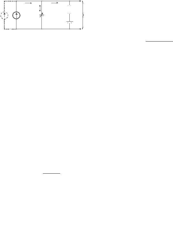
The model can be displayed as an electrical analogy (Fig. 2). The model is described mathematically as a differential equation of the time-dependent ICP as a function of external infusion and the governing physical parameters:
dPIC t |
|
|
K |
½PICðtÞ&2 K |
|
K Pr |
PICðtÞ ¼ 0 |
ð |
Þ |
þ |
|
IinfusionðtÞ þ |
|
||
dt |
|
Rout |
Rout |
||||
|
|
|
|
|
|
|
ð2Þ |
4 HYDROCEPHALUS, TOOLS FOR DIAGNOSIS AND TREATMENT OF
|
Itotal |
Iabsorption |
|
|
|
|
Istorage |
Rout |
|
|
|
|
PIC |
|
|
|
C=1/(K PIC ) |
|
|
|
|
|
(ICP) |
|
|
|
|
|
|
Iinfusion |
Iformation |
|
P |
sinus |
|
|
|
|
Figure 2. Model of the dynamics of the CSF system. Iformation is the CSF formation rate, C is the pressure-dependent compliance described by the elastance parameter K, Rout is outflow resistance,
Psinus is the venous pressure in the sinus, and PIC is the intracranial pressure. Iinfusion is the option of external infusion of artificial CSF.
where Rout is outflow resistance, PIC is the intracranial pressure, Pr is the ICP at rest, and K is the elastance.
Estimation of CSF outflow resistance and the other system parameters requires perturbation of the system steady state by infusion of fluid into the craniospinal system, either through a lumbar or a ventricular route. Typically, one or two needles are placed in the lumbar canal. When two needles are used, one is connected to a pressure transducer for continuous recording of the dynamic changes in ICP following the infusion, and the other one for infusion and/or withdrawal of the fluid. Different protocols of infusion will lead to unique mathematical solutions. In addition to the resting pressure (also refereed to as opening pressure), which always is determined during these investigations, it is generally believed that the outflow resistance is the clinically most important parameter, but compliance has also been proposed as a predictor for outcome after shunting.
Bolus Infusion. An example of ICP recoding during the bolus infusion test is shown in Fig. 3. The approach is to first determine the compliance from the ratio of the injected volume and the magnitude of pressure increase (30). A pressure volume index (PVI), which describes compliance, is calculated through the expression:
DV |
|
PVI ¼ logðPp=P0Þ |
ð3Þ |
Figure 3. ICP curve from a bolus injection of 4 mL. Figure from Marmarou et al. (30).
where DV is the infused volume, Pp is the peak pressure and P0 is the initial pressure just before the infusion. The next step is to determine Rout from the spontaneous relaxation curve when the ICP returns toward the resting pressure (Fig. 3). Solving the differential equation for the relaxation phase after the bolus infusion gives the following expression for Rout as a function of time (31):
Rout ¼ |
|
|
tP0 |
|
ð4Þ |
PVI log |
|
Pt=PpÞðPp P0Þ |
|
||
|
|
|
|||
ð |
Pt P0 |
|
|||
where t is the time in seconds after the bolus and Pt is the measured pressure at time t on the relaxation curve. From each bolus, a number of values of Rout are calculated and averaged, for example at t ¼ 1 min, 1.5 min, and 2 min. The bolus procedure is usually repeated a couple of times for increased measurement reliability.
Constant Pressure Infusion. In this infusion protocol, several constant ICP levels are created. This is done by using a measurement system that continuously records the ICP and regulates it by controlling the pump speed of an infusion pump (Fig. 4) (32). The net infusion rate needed to sustain ICP at each pressure level is determined, and a flow versus pressure curve is generated (Fig. 4). Using linear regression, the outflow resistance is then determined from the slope of that curve (33), because at steady state, the differential equation reduces to
1 |
|
Pr |
|
|
Iinf ¼ |
|
PIC |
|
ð5Þ |
Rout |
Rout |
|||
where PIC is the mean intracranial pressure on each level,
Pr is the resting pressure, and Iinf is the net infusion flow at each level.
The constant pressure method can also be used to estimate the CSF formation rate. This is done by lowering the ICP beneath the venous pressure, i.e., below 5 mm Hg. At that ICP, no CSF reabsorption should take place. Therefore, the net withdrawal of CSF needed to sustain that constant pressure level should equal the formation rate.
Constant Flow Infusion. In this method, both the static and the dynamic behavior of the CSF system can be used to estimate outflow resistance (34). In a steady-state analysis Rout can be calculated from the stable ICP value associated with a certain constant infusion rate. Rout is then estimated by the following expression:
R |
out;stat ¼ |
Plevel Pr |
ð |
6 |
Þ |
|
Iinf |
|
where Rout,stat is a static estimation of Rout, Plevel is the new equilibrium pressure obtained at the constant infusion
rate, Pr is the resting pressure, and Iinf is the infusion rate (Fig. 5).
Rout can also be estimated from the dynamic phase during the pressure increases toward the new equilibrium (Fig. 5). This procedure will also give an estimate of the craniospinal compliance (elastance). The differential equation is now solved for a condition of a constant infusion rate, and the solution is fitted against the recorded pressure
HYDROCEPHALUS, TOOLS FOR DIAGNOSIS AND TREATMENT OF |
5 |
45 |
|
|
|
|
160 |
|
|
4 |
|
|
|
|
40 |
ICP |
|
|
|
140 |
|
|
|
Flow = 0.13 ICP - 0.93 |
|
|
|
|
|
|
|
|
|
|
|
|
|
|||
|
Net infusion |
|
|
|
|
|
|
|
|
|
||
35 |
|
|
|
120 |
|
|
3 |
|
|
|
|
|
|
|
|
|
|
|
|
|
|
|
|||
|
|
|
|
|
|
|
|
|
|
|
||
30 |
|
|
|
|
60 |
Vol[ml] |
[ml/min]Flow |
|
|
|
|
|
[mmICPHg] |
|
|
|
|
|
|
|
|
|
|||
|
|
|
|
|
100 |
|
|
|
|
|
|
|
25 |
|
|
|
|
80 |
|
|
|
|
|
|
|
20 |
|
|
|
|
|
|
2 |
|
|
|
|
|
|
|
|
|
|
|
|
|
|
|
|
|
|
15 |
|
|
|
|
|
|
|
|
|
|
|
|
10 |
|
|
|
|
40 |
|
|
1 |
|
|
|
|
|
|
|
|
|
|
|
|
|
|
|
|
|
5 |
|
|
|
|
20 |
|
|
|
|
|
|
|
|
|
|
|
|
|
|
|
|
|
|
|
|
0 |
|
|
|
|
0 |
|
|
0 |
|
|
|
|
00:00 |
00:20 |
00:40 |
01:00 |
01:20 |
01:40 |
|
|
15 |
20 |
25 |
30 |
35 |
|
|
Time [h:min] |
|
|
|
|
|
|
ICP [mm Hg] |
|
|
|
Figure 4. Pressure and flow curves for the constant pressure method. Left graph shows typical data for ICP and infused CSF volume versus time. Right graph shows the mean pressure and flow points determined from each steady-state level. Outflow resistance corresponds to the inverse of the slope.
curve. The time-dependent pressure increase is described by the following expression:
|
|
|
|
|
|
|
|
|
|
|
|
|
|
|
|
|
I |
|
Pr P0 |
ð |
P |
r |
P |
Þ |
|
|
|||
PðtÞ ¼ |
|
inf þ Rout;dyn |
|
0 |
þ P0 |
ð7Þ |
||||||||
|
|
|
|
|
|
Pr |
P0 |
|
|
|
||||
|
Pr |
P0 |
|
|
K |
|
|
|
þIinf |
t |
|
|
||
|
|
|
Rout;dyn |
|
|
|||||||||
|
|
|
þ |
I |
e |
|
|
|
|
|
|
# |
|
|
Rout;dyn |
inf |
" |
|
|
|
|
|
|
|
|||||
where K is the elastance and P0 is a reference pressure that is suggested to be equal to venous sinus pressure. Fitting against data will result in estimations of the unknown
parameters Rout,dyn, K, and P0.
In summary, CSF infusion tests are conducted to reveal parameters describing the hydrodynamics of the craniospinal system. An active infusion of artificial CSF is performed, and the resulting ICP response is recorded, and parameters such as outflow resistance, compliance, formation rate, and the venous sinus pressure are then estimated based on a proposed mathematical model. Outflow resistance values determined with the bolus method are usually lower than the values determined with the constant infusion and constant pressure methods. The reason for this difference is not well understood at this time. Determina-
tion of Rout is often used as a predictive test in hydrocephalus, and it has been stated that if the outflow resistance exceeded a certain threshold, it is an excellent predictor of clinical improvement after shunting (35). In a recent guideline for idiopathic normal pressure hydrocephalus, measurement of Rout is included as a supplementary test for selecting patients suitable for shunt surgery (36).
DIAGNOSIS WITH IMAGING
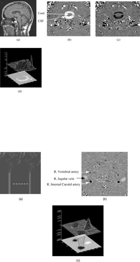
Cross-sectional imaging is routinely used in the diagnosis of hydrocephalous. CSF spaces are well visualized with CT and MRI. In CT images, CSF spaces appear darker due to the lower atomic density of the CSF compared with that of brain tissue. MRI provides an excellent soft-tissue contrast resolution and is considered the primary imaging modality for brain imaging. With MRI, CSF spaces can appear either darker or brighter compared with its surrounding tissues depending on the imaging technique. An example of a CT image and MRI images demonstrating abnormally large CSF spaces is shown in Fig. 6. Cross-sectional imaging enables quantitative assessment of the CSF spaces as well
Figure 5. ICP data from a constant infusion investigation. Figure modified from Czosnyka et al. (34).

6 HYDROCEPHALUS, TOOLS FOR DIAGNOSIS AND TREATMENT OF
Figure 6. An example of a (a) CT image and (b and c) MRI images demonstrating abnormally large CSF spaces. The appearance of CSF in MRI depends on the technique used to acquire the images; its
(b) dark with a T1 technique and (c) bright with a T2 technique.
as 3D reconstruction of the geometry of the ventricular system. The 3D model is obtained by segmentation of the CSF spaces in each of the 2D slices. An example of 3D models of the ventricular system from MRI data demonstrating normal size ventricles and enlarged ventricles are shown in Fig. 7a and b, respectively.
MRI-based motion-sensitive techniques capable of imaging flow are gaining an important role in the diagnosis of hydrocephalus. In particular, dynamic phase-contrast techniques provide images of velocities (velocity-encoded images). The degree of brightness in these images is proportional to the direction and the speed of the moving fluid or tissue. Dynamic (cine) phase contrast images are used to visualize the back and forth flow through the different CSF pathways. The cine phase contrast MRI (PCMRI) technique is also used to derive quantitative parameters such as CSF volumetric flow rate through the aqueduct of Sylvius, from which the CSF production rate in the lateral ventricles can be estimated (37), and intracranial compliance and pressure (19,30).
MRI-Based Measurement of Intracranial Compliance and
Pressure
The noninvasive measurement of compliance and pressure uses the cardiac pulsations of the intracranial volume and
pressure (30,38). This method is the noninvasive analogs to the measurement of intracranial compliance with the previously described bolus infusion method where the volume and pressure changes are calculated from the MRI measurements of CSF and blood flows to and from the brain. Intracranial elastance, i.e., a change in pressure due to a small change in volume, or the inverse of compliance, is derived from the ratio of the magnitudes of the changes in volume and pressure, and the pressure is then derived through the linear relationship between elastance and pressure. The MRI method measures the arterial, venous, and CSF flows into and out of the cranial vault. A smallvolume change, on the order of 1 mL, is calculated from the momentary differences between inflow and outflow at each time points in the cardiac cycle. The pressure change is proportional to the pressure gradient change, which is calculated from time and spatial derivatives of the CSF velocities using fluid dynamics principles.
A motion-sensitive MRI technique, cine phase contrast, provides a series of images where the value at each picture element is proportional to the velocity at that location. The phase contrast MRI technique is based on the principle that the precession frequency of the protons is proportional to the magnetic field strength. Therefore, velocity can be phased-encoded by varying the magnetic field in space and time, i.e., generating magnetic field
Figure 7. Volume rendering of the CSF spaces inside the brain (i.e., ventricles) generated using segmented MRI data from a (left) healthy volunteer and from a (right) hydrocephalic patient.
HYDROCEPHALUS, TOOLS FOR DIAGNOSIS AND TREATMENT OF |
7 |
gradients. When a gradient field is applied along an axis for a short time, the proton’s phase will change based on its location along that axis. When a bipolar (positive and then negative) gradient field is applied, the phase of the stationary protons will increase during the positive portion (lobe) of the bipolar gradient and then will decrease during the negative lobe. If the lobes were of equal area, no net phase change would occur. However, moving protons, such as those in the blood or CSF, will experience different field strength during each lobe due to their
Figure 8. (a) Anatomical midsagittal T1-weighted MR image showing the location of the axial plane used for CSF flow measurement (dark line). (b and c) Phase-contrast MRI images of CSF flow in the spinal canal.
(b) CSF flow during systole. (c) CSF flow during diastole. The pixel values in these images are proportional to velocities in a direction perpendicular to the image plane. Gray-static tissue, whiteoutward flow (caudal direction), and black-inward flow (cranial direction).
(d) A 3D plot of the CSF velocities during systole.
change in position; this will result in a net phase change proportional to the proton velocity.
Examples of MRI phase contrast images of CSF and blood flow are shown in Figs. 8 and 9, respectively. The oscillatory CSF flow between the cranial and the spinal compartments is visualized in images taken in a transverse anatomical orientation through the upper cervical spinal canal. The location of this plane is indicated on a midsagittal scout MR image shown in Fig. 8a. Fig. 8b depicts outflow (white pixels) during systole, and Fig. 8c depicts
Figure 9. (a) A blood vessel MRI scout image showing the location of the axial plane for blood flow measurement (dash line). (b) A phase contrast MRI image of blood flow through that location. Black pixels indicate arterial inflow, and white are venous outflow. (c) A 3D plot of the blood flow velocities.
8 HYDROCEPHALUS, TOOLS FOR DIAGNOSIS AND TREATMENT OF
|
1400 |
|
|
|
|
csf |
|
|
|
|
|
|
|
|
1200 |
|
|
|
|
a |
|
1000 |
|
|
|
|
v |
(mL/min) |
|
|
|
|
|
|
800 |
|
|
|
|
|
|
600 |
|
|
|
|
|
|
Flow |
|
|
|
|
|
|
400 |
|
|
|
|
|
|
|
200 |
|
|
|
|
|
|
0 |
|
|
|
|
|
|
–200 |
|
|
|
|
|
|
0 |
200 |
400 |
600 |
800 |
1000 |
Time (ms)
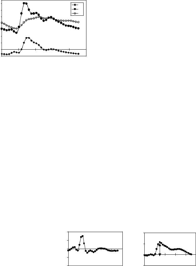
Figure 10. The volumetric flows into and out of the cranial vault during the cardiac cycle derived from the MRI phase contrast scans. Total arterial inflow (filled circles), venous outflow (open), and the cranial-to-spinal CSF volumetric flow rate (diamonds) during the cardiac cycle. Note that arterial inflow is greater than venous outflow during systole.
inflow (black pixels) during diastole. Fig 9d depicts a 3D plot of the velocities in a region of interest containing the CSF space and an epidural vein. The CSF flow is imaged with a low-velocity encoding, and the faster blood flow through the neck arteries and veins is imaged using high-velocity encoding. The location of the imaging plane used for blood flow measurement is shown in Fig. 9a, and a velocity encoded image of blood flow is shown in Fig. 9b. Fig 9c depicts a 3D plot of the velocities in a region of interest containing the internal carotid and vertebral arteries and the jugular vein.
Volumetric flow rates are obtained by integration of the velocities throughout a lumen cross-sectional area. The total volumetric arterial flow rate—that is, total cerebral blood flow—is calculated directly from the sum of the volumetric flow through the four vessels carrying blood to the brain (internal carotid and vertebral arteries). The venous blood outflow is obtained by summation of the flow through the jugular veins, and through secondary venous outflow channels such as the epidural, vertebral, and deep cervical veins when venous drainage occurs through these veins. An example of the volumetric flow waveforms for CSF, arterial inflow, and venous outflow measured in a healthy volunteer is shown in Fig. 10.
The rate of the time-varying intracranial volume change (net transcranial volumetric flow rate) is obtained by sub-
tracting outflow rates from inflow rates at each time point. The intracranial volume change (delta of volume from a given reference point) is obtained by integrating that waveform with respect to time. Waveforms of the net transcranial volumetric flow rate and the change in the intracranial volume are shown in Fig. 11.
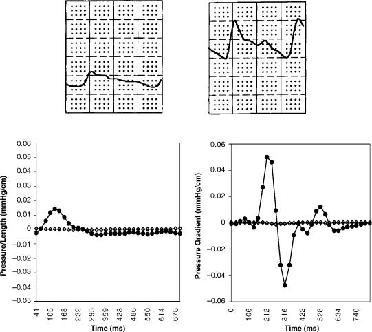
The magnitude of the change in intracranial pressure during the cardiac cycle (pulse pressure) is proportional to that of the CSF pressure gradient waveform. A method to measure pressure gradient of pulsatile flow in tubes with MRI was reported by Urchuk and Plewes (39). Pulsatile pressure gradients are derived from the MRI velocityencoded phase contrast images using the Navier–Stokes relationship between pressure gradient and temporal and spatial derivatives of the fluid velocity for incompressible fluid in a rigid tube (40). Pressure traces from invasive recordings obtained invasively in patients with low and elevated ICP with an intraventricular pressure transducer and the corresponding CSF pressure gradient waveforms derived from the MRI measurements of the CSF velocities at lowand high-pressure states are shown in Fig 12. The ratio of the magnitude of the pressure and volume changes, i.e., intracranial elastance, is then expressed in terms of MR-ICP based on the linear relationship between elastance and ICP.
DEVICES FOR TREATMENT
Despite significant advances in understanding of the pathophysiology of hydrocephalus, the gold standard for the treatment of hydrocephalus still continues to be CSF diversion through a tube shunt to another body cavity. Unfortunately, treatment with CSF shunts is associated with multiple complications and morbidity. The rate of shunt malfunction in the first year of shunt placement is 40%, and, thereafter, about 10% per year. The cumulative risk of infection approaches 20% per person although the risk of infection per procedure is only 5–8% (41). The technological advances in shunt valve designs and materials have had only a marginal impact on the rate of complications. Third ventriculostomy has become popular in recent years for management of obstructive hydrocephalus, but many questions about its long-term permanence remain controversial. Choroid plexectomy (42,43) aimed at arresting hydrocephalus by reducing CSF production or pharmacotherapy with similar intentions have had very limited success in selected patients.
Figure 11. (Left) The MRI-derived net transcranial volumetric flow rate waveform. (Right) The intra cranial volume change during the cardiac cycle derived by integrating the net transcranial volumetric flow waveform on the left. Note that the maximal volume change in this subject is 0.5 mL.
|
500 |
|
|
|
|
|
|
0.8 |
|
|
|
|
|
Flow (mL/min) |
250 |
|
|
|
|
|
ICVC (mL) |
0.4 |
|
|
dV = 0.5mL |
|
|
|
|
|
|
|
|
|
|
|
|
|
|||
0 |
|
|
|
|
|
|
|
|
|
|
|
||
–250 |
|
|
|
|
|
0 |
|
|
|
|
|
||
|
|
|
|
|
|
|
|
|
|
|
|||
|
|
|
|
|
|
|
|
|
|
|
|
||
|
–500 |
|
|
|
|
|
|
–0.4 |
|
|
|
|
|
|
0 |
200 |
400 |
600 |
800 |
1000 |
|
0 |
200 |
400 |
600 |
800 |
1000 |
|
|
|
Time (ms) |
|
|
|
|
|
Time (ms) |
|
|
||
HYDROCEPHALUS, TOOLS FOR DIAGNOSIS AND TREATMENT OF |
9 |
Figure 12. Invasive pressure traces (top) obtained with an intra-ventricular catheter from two patients with (left) low and (right) elevated ICP. The corresponding MRI-derived CSF pressure gradients are shown at the bottom.
Nonobstructive Hydrocephalus
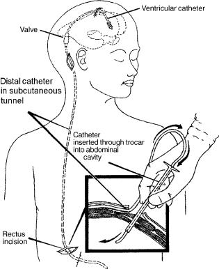
No treatment other than CSF diversion has been effective in management of this form of hydrocephalus. The CSF may be diverted from the ventricles through a catheter that runs in the subcutaneous tissue into the abdominal cavity where it is absorbed by the peritoneum (ventriculoperitoeal shunt) (Fig. 13). It may also be diverted from the spinal subarachnoid space by a lumbar shunt that diverts it to the peritoneum (Lumbar-peritoneal shunt). Lumbar CSF diversion avoids the potential risk of brain injury by the ventricular catheter. Lumbar shunts have a lower risk of obstruction and infection (44) but are more prone to malfunction from mechanical failures (45), and, the development of hind brain herniation, over a period of time, has been well documented (46,47). Evaluation of a lumbar shunt for function is more cumbersome than that of a ventricular shunt. The lumbar shunt is usable in patients with communicating hydrocephalus, small ventricles, and patients who have had multiple ventricular shunt malfunctions.
In patients who cannot absorb CSF from the peritoneum due to scarring from previous operations or infections, the CSF may be diverted to the venous system through a
catheter placed at the junction of superior vena cava and the right atrium (ventriculo/lumbar-atrial shunt).
A typical shunt system consists of three parts (Fig. 14). First, the proximal catheter, i.e, the catheter, is inserted into the ventricle or the lumbar subarachnoid space. Second, the valve controls the amount of CSF that flows through the shunt system, and third, the distal catheter drains the CSF from the valve to the peritoneum or the atrium.
Proximal Catheter
Three basic types of proximal catheter designs are available: simple with multiple perforations (Codman, Raynham, MA; PS Medical, Goleta, CA), simple Flanged (Heyer-Schulte), Integra, Plainsboro, NJ; Anti-Blok (Phoenix Vygon Neuro, Valley Forge, PA) with receded perforations. The last two have been designed to minimize the growth of choroid plexus into the perforations and causing obstruction. There is no controlled study to suggest that these two designs are in any way superior to simple perforations. The flanged catheters can get stuck, as choroid plexus grows around it, making removal of an obstructed catheter difficult (48).
10 HYDROCEPHALUS, TOOLS FOR DIAGNOSIS AND TREATMENT OF
Figure 13. The shunt consists of three parts. The ventricular catheter enters the skull through a burr hole in the skull and passes through the brain into the lateral ventricle. It is connected to the valve that is placed in the subcutaneous tissue of the scalp. The valve in turn is connected to the distal catheter that runs in the subcutaneous tissue to enter the peritoneal cavity of the abdomen as shown in the inset (ventriculo-peritoneal shunt) or into the jugular vein and through it to the superior vena cava (ventriculo-atrial shunt).
Placement of the proximal catheter has generated considerable controversy in the literature (48–51). More recently, endoscopic placement of the proximal catheter into the frontal horn, away from the choroid plexus, has been advocated to minimize proximal malfunction (3,52,53). Again no controlled study has been done to confirm whether placement of the proximal catheter into frontal or occipital horn is superior to placement in the body of the lateral ventricle. Often catheters that are grossly malpositioned may continue to work, whereas those that are well positioned may fail. The choice of the site, frontal or parietal, may be made on the basis of the above although some studies have suggested a higher incidence of seizure with catheters placed via a frontal burr-hole (49). A study to evaluate use of endoscope to place the shunt catheter in the frontal horn failed to show any benefit (54). This suggests that no matter where the catheter is placed, the flow of CSF toward the catheter causes the choroids plexus to creep toward the catheter, ultimately causing ingrowth and obstruction of the catheter (55).
To remove an obstructed catheter, intraluminal coagulation of the choroid plexus is done using a stylet and lowvoltage diathermy, at the time of shunt revision (56–58). Massive intraventricular hemorrhage may occur if the
choroid plexus is torn while forcefully removing the catheter. Delayed subarachnoid hemorrhage from rupture of pseudoaneurysm resulting from diathermy of a catheter close to anterior cerebral artery has been reported (59). At times, if the ventricular catheter is severely stuck, it is advisable to leave it in position but occlude it by a ligature and clip. This may become necessary as sometimes an occluded catheter may become unstuck over time and begin to partially function, resulting in formation of subgaleal CSF collection. Replacing a new catheter into the ventricle in patients with small or collapsed ventricles can be sometimes challenging. In most instances, after removal of the old catheter, the new catheter can be gently passed into the ventricle through the same tract. Frameless stereotaxis (StealthStation, Medtronics, Goleta, PA) is now available and may offer an alternative to cumbersome and timeconsuming frame-based stereotactic catheter placement (52).
Valve
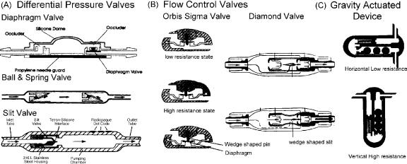
The valve regulates the amount of CSF that is drained. The aim is to maintain normal ICP. The simplest valves are differential pressure valves. The CSF drainage in these valves is based on the pressure difference between the proximal and the distal ends. Three major configurations are available (Fig. 14): diaphragm, slit valve, and ballspring mechanism in different pressure ranges (low, medium, and high). Recently, valves in which the pressure setting can be changed with a magnetic wand have become available. These programmable valves allow pressure changes over different pressure ranges based on the manufacturer. The pressure setting on the valve can be ascertained by X ray of the head in the Medos valve (Codman, Raynham, MA) or using a magnetic wand in the Strata valve ( Medtronics, Goleta, CA). To prevent inadvertent changes in the valve setting by stray magnetic fields, the Polaris valve (Sophysa, Costa Mesa, CA) has an ingenious locking mechanism that allows changes only if the magnetic field has a certain configuration.
Slit valves tend to be the most inaccurate in their performance followed by ball and spring valves. The diaphragm valves proved to be most stable in long-term tests. Most valves, like the slit valves, ball–spring, and diaphragm valves, offer a lower resistance (<2.5 mm Hg/ mL/min) than the normal physiological CSF outflow of 6–10 mm Hg/mL/min. The standard distal tubing of 110 cm increases the overall resistance to 50–80% of the physiological value (60).
Standard differential pressure valves are available in different pressure ranges. It is unclear whether it makes a difference in an ambulatory patient to use a low-, medium-, or high-pressure valve because in the upright position irrespective of the rating the hydrostatic column converts all differential pressure valves into ‘‘negative’’ pressure valves (61). The overdrainage results in persistent headaches from low ICP, ventricular collapse, and increased risk of shunt obstruction. Long-term changes in cerebrovenous physiology cause acute and severe increase in ICP without enlargement of ventricles at the time of shunt malfunction (62). To circumvent the overdrainage in the
HYDROCEPHALUS, TOOLS FOR DIAGNOSIS AND TREATMENT OF |
11 |
Figure 14. Three major types of valve designs are available. (a) Differential pressure valves allow flow in proportion to the pressure difference between the proximal catheter and the distal catheter. Configurations are a simple diaphragm, ball and spring, or slit valve. Programmable differential pressure valves can be programmed to a pressure setting using a magnetic wand. In the upright position, due to a negative pressure from the hydrostatic column of fluid in the distal catheter, these valves tend to overdrain causing negative pressure symptoms. (b) Flow control valves have the ability to limit overdrainage from a negative hydrostatic pressure gradient. The Orbis-Sigma Valve has a wedge-shaped pin over which the orifice of the diaphragm (arrows) rests. When the distal pressure becomes negative in the upright position, the diaphragm slides downward on the pin narrowing the drainage channel and hence reducing the flow rate. The Diamond valve has a wedge-shaped slit in the construct (arrows) that narrows as the distal pressure becomes increasingly negative again reducing the flow rate. (c) Gravity actuated devices reduce drainage in the upright position by increase in resistance to flow of CSF from the weight of metal balls in the drainage channel.
upright position, ingenious devices, also referred to as devices for reducing siphoning (DRS), have been developed (Fig. 14). The Anti-Siphon device (Integra LifeSciences) has a flexible diaphragm that mechanically senses atmospheric pressure and shuts off the drainage channel if the hydrostatic pressure in the fluid column becomes negative. Flow control valves (Orbis Sigma Valve, Integra LifeSciences and Diamond Valve, Vygon Neuro, Valley Forge, PA) have a drainage channel that narrows as the differential pressure increases in the upright position to reduce the flow. Gravity actuated devices (Gravity Compensating Accessory, Integra LifeSciences, CA, Chabbra Shunt) have metal balls that fall over one another in the upright position to increase resistance to flow. Double channel devices (Dual Switch Valve, Christoph Miethke GmBH & Co KG; SiphonGuard, Codman) have two channels; the low-resis- tance channel is shut off by a gravity actuated ball in the upright position.
There is no evidence to suggest that use of one type of valve is superior to the other, and several valve designs are available in the market today. A recent multicentric study, evaluating three basis types of valves, failed to confirm the utility of flow control or anti-siphon valves in children and infants over the differential pressure valves (10). Similarly, studies have failed to show that programmable devices are superior to fixed pressure valves (63). Over a period of time, the ventricle tended to become small irrespective of the type of valve used. The rate of proximal malfunction in a patient with flow control valves was 6.5% compared with 42–46% for the other two valves, although the overall rate of malfunction and shunt survival was not statistically
different. The design of the flow control valves with a narrow orifice makes it sensitive to malfunction (64). Certainly, revising a valve has less morbidity and risk of neurological injury than revising the proximal catheter, especially in patients with slit ventricles. There is evidence that a significant number of patients do not tolerate flow control valves and, despite a radiologically functioning shunt, have high intracranial pressure from underdrainage through the valve. In patients with limited pres- sure–volume compensatory reserve, there can be an excessive increase in intracranial pressure during cardiovascular fluctuations, especially at night and be responsible for nighttime or early morning headaches, in patients with flow control devices (60). Self-adjusting diaphragm valves like the Orbis-Sigma (Integra LifeSciences), on bench test, have proved to be inaccurate and unstable at perfusion rates of 20–30 mL/h, which is the most important physiological range, leading to pre-valve pressures rapidly changing between 4 and 28 mm Hg. During long-term perfusion, these may resemble ICP pressure waves (60).
Diaphragm-based anti-siphon devices are prone to obstruction from encapsulation as has been shown in experimental animals and is often encountered in patients who have had recurrent malfunctions (65). Some patients are more prone to develop heavy scarring around the shunt system. Again, there is no evidence that using an open (ASD, Anti Siphon device, Integra LifeSciences) has any advantage over using a closed system that opens when the pressure exceeds the negative hydrostatic pressure (SCD, Siphon Control Device, Medtronics), although theoretically malfunctions in an open system would only result in loss of
12 HYDROCEPHALUS, TOOLS FOR DIAGNOSIS AND TREATMENT OF
anti-siphon function without obstruction to the flow of CSF. In the open system (ASD), the flow through the valve stops only after the intracranial pressure has become negative in the upright position, which is more physiological, than with SCD, in which the flow stops once the pressure reaches zero. In the multicentric shunt study, the incidence of overdrainage was 7.8% in the SCD group and 2.6% in the Standard valve group. The study suggests that diaphragm-based anti-siphon devices may not be any superior to differential pressure valves in reducing overdrainage (10). Considerable controversy also revolves around the most optimum site for placement for the anti-siphon devices (66,67). The classic position is at the level of the skull base: however, the bench test suggests a marked tendency to overdrain if the SCD is below the level of the proximal catheter. These factors may be minor when considered in light of the excessive sensitivity of the SCD to external pressure from scar or when the patient is lying on the device (64).
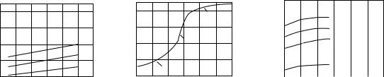
The gravity actuated device (GAD) is used in conjunction with a differential pressure valve to limit overdrainage (68). It is similar to the horizontal vertical valve used in lumbar shunts but constructed to fit in-line with a ventriculoperitoneal shunt. There is no literature to prove or disprove its utility; however, in individual cases, we have found it effective. Experimental evidence suggests that motion and vibration (35) make the mechanism of these devices ineffective although clinical studies are lacking. The position of the GAD device is critical for optimum functioning. Slight angulation of the device to vertical can cause underdrainage in the horizontal position and overdrainage in the vertical position. Examples of pressure flow characteristics of a standard differential pressure valve, a flow control valve, and a valve containing a GAD are shown in Fig. 15.
Distal Catheter
Distal shunt malfunction is reported to occur in 12% to 34% of shunts (51,69). Three types of distal catheters have been used: the closed ended with side slits, open ended with side slits, and open ended. A higher incidence of distal catheter obstruction has been noted in catheters with side slits whether closed ended or open ended (51,70). Omental ingrowth is responsible for the peritoneal catheter obstruc-
tion; possibly the distal slits act as collection points for the debris and provide a channel for trapping the omentum. It is unclear whether using open-ended distal catheters increases the likelihood of small ventricle malfunction. Use of extended length catheters (110–120 cm) is not associated with an increase in the complications and eliminates the need to lengthen the peritoneal catheter for growth of the patient (71). However, care must be taken to identify patients who may have enough length of tubing in the abdomen but may underdrain due to a narrow and taught segment of tubing from subcutaneous tethering as a result of scarring and calcification.
It is difficulty to justify use of atrial over the peritoneal site for distal absorption (72,73). Data on 887 patients suggested that atrial shunts have a higher rate of malfunction although some studies have not shown a significant difference. However, when the same information was stratified by age, shunt type, and time period, there was no significant difference in shunt durability. Cardio-pulmonary complication, such as irreversible pulmonary hypertension, endocarditis, and glomerulonephritis, are some of the more serious complications that may occur with atrial shunts (73). Alternative sites, like pleura, may result in significant negative pressures in the shunt system (74). Poor absorption from the pleura may result in large pleural effusions in small children (74). The gall bladder has also been effectively used in patients in whom peritoneal, atrial, or pleural sites have been exhausted (75,76). Potential complications of these shunts, notably biliary ventriculitis and biliary meningitis, have been reported in the literature (77,78). The ventriculo-femoral shunt may be tried in patients with a difficult access to the atrium from the subclavian or jugular route (79). Trans-diaphragmatic placement of the distal catheter in the sub-hepatic space worked successfully in one reported patient with poor peritoneal access due to scarring (80).
Shunt Material
Ideal shunt material should be completely biocompatible, be easy to handle, flexible, resistant to infection, and nonmetallic but radio-opaque (metals interfere with MRI imaging). From a manufacturing standpoint, it should be easy
O) |
400 |
|
|
|
|
|
|
|
|
|
|
|
|
|
|
2 |
|
|
|
|
|
|
|
H |
300 |
|
|
|
|
|
|
(mm |
|
|
|
|
|
|
|
200 |
|
|
|
|
High |
||
Pressure |
|
|
|
|
|||
|
|
|
|
Low |
|||
100 |
|
|
|
|
|||
|
|
|
|
|
|
Medium |
|
|
0 |
10 |
20 |
30 |
40 |
50 |
60 |
|
0 |
||||||
|
|
|
Flow (cc/hr) |
|
|
|
|
Pressure (mm H O) 2
400
300
200
100
0
0
Low resistance (safety Valve)
High resistance
Low resistance
10 |
20 |
30 |
40 |
50 |
60 |
Flow (cc/hr)
Pressure (mm H O) 2
400 |
4 Balls vertical |
|
|
||
300 |
|
|
3 Balls vertical |
||
|
||
200 |
2 Balls vertical |
|
|
||
100 |
|
|
All valves |
||
|
||
|
horizontal |
0 |
|
|
|
|
|
|
|
|
|
|
|
|
|
|
|
0 |
10 |
20 |
30 |
40 |
50 |
60 |
|
|
|
|
Flow (cc/hr) |
|
|
|
|
Figure 15. Pressure flow characteristics of (a). Standard differential pressure valve; note that with increasing differential pressure, such as from upright posture, there is an increase in the flow rate. (b) The flow control valve has a sigmoid flow-pressure relationship; in the upright position, the valve works at the high resistance stage and maintains a relatively steady flow rate despite increase in differential pressure. (c) Gravity actuated device, in vertical position acts as a very highresistance differential pressure valve (depending on the number of balls in the device) and as a low-resistance differential pressure valve in the supine position.
HYDROCEPHALUS, TOOLS FOR DIAGNOSIS AND TREATMENT OF |
13 |
to mold into tubing and making valve components. Silicone polymer is probably the best available material for this purpose.
Some studies have suggested development of silicone allergy in some patients with ventricular shunts (81–84). It is unclear whether it represents a true immunological reaction or a nonspecific foreign body type granulomatous reaction (85). In patients with suspected or documented silicone allergy, use of polyurethane (86) or, more recently CO2 extracted silicone catheters has been postulated but not proven to offer some advantage in reducing risk of recurrent malfunctions.
Subcutaneous location of the distal catheters makes them susceptible to degradation from a foreign-body reaction mounted by the body (87). Scarring around the catheter, calcification, and stress fractures are long-term consequences of this reaction (88,89). Unless there is some amount of surface degradation, the adhesions to the subcutaneous tissues do not occur (87). Evidence suggests that barium used in the silicone catheters is probably not an important factor in promoting calcification and degradation (90). Use of barium-free catheters, however, makes it difficult to evaluate a shunt system on radiological imaging.
To minimize colonization of shunt catheters and infection, recently antibiotic-coated catheters have become available. The catheters are available coated with rifampin and minocycline (Medtronics, Goleta, CA) and another with rifampin and clindamycin (Bactiseal, Codman, Raynham, MA). The antibiotic is most active against Staph epidermidis, which is the cause of shunt infection in most patients. The antibiotic gradually leaches out of the catheter over a 30–60 day period providing added advantage. Control studies have shown a significant reduction in rate of infection with use of these catheters (91,92). The major drawback is the excessive cost of the antibiotic-coated catheters.
Shunt Malfunction
About 30–40% of the shunts malfunction within the first year of placement (10) and 80% of malfunctions are proximal malfunctions. Although most patients with a malfunctioning shunt will present with the classic features of raised pressure, headache, and vomiting, in 20%, there may be no signs of raised pressure (93). Instead, this group of patients present with a subtle change in behavior, decline in school performance, gait disturbances, and incontinence. Some patients may present with aggravation in the signs and symptoms of Chiari malformation or syringomyelia. Parents are often more sensitive to these subtle changes. In a study comparing the accuracy of referral source in diagnosing shunt malfunction, parents were more likely to be correct about the diagnosis as compared with a hospital or general practitioner (94).
At examination, a tense fontanelle, split sutures, and swelling at the shunt site are very strongly suggestive of a malfunctioning shunt. Shunt pumping has a positive predictive value of only 20% (95). A shunt valve that fails to fill up in 10 minutes is very strongly suggestive of shunt malfunction. Radiological assessment may demonstrate a fracture or dislocation. Presence of double-backing of the distal catheter, wherein the distal catheter tip loops out of
the peritoneal through the same spot that it enters it, is diagnostic of distal malfunction (96). The shunt tap gives useful information about the proximal and distal shunt system. The absence of spontaneous flow and poor drip rate indicate proximal malfunction, whereas a high opening pressure is suggestive of distal malfunction (97). The presence of increase in size of the ventricles on CT scan confirms a malfunctioning shunt; however, a large number of patients with long-standing shunt have altered brain compliance and may not dilate the ventricles at the time of presentation. In children, similar symptoms occur in the common illnesses like otitis media; gastroenteritis of viral fevers often confound the diagnosis. Radiological assessment of shunt flow using radionuclide or iodide contrast media injected into the shunt may help (2,98–100). Unfortunately, although some studies have shown an accuracy of 99% with combined pressure and radionuclide evaluation (98,101), others have shown a 25–40% incidence of deceptive patency when evaluated by radionuclide cisternogram (97). This could stem from a partial but inadequately functioning shunt, intermittent malfunction, or presence of isolated ventricle. Similar problems are encountered with an iodide contrast-based shuntogram or shunt injection tests. In the absence of normative data with regard to adequate flow in the shunt, which may vary significantly with the individual, time of the day, and activity (102), use of Doppler-based flow devices, flow systems that work based on differential temperature-gradient or MRI-based flow systems becomes irrelevant for an individual patient. Lumbar infusion tests and shunt infusion tests to assess the outflow resistance through the shunt are cumbersome and require a laboratory-based setup and may not be possible in an ER setting (103–105). Infusion through a reservoir to assess outflow resistance through the shunt suggests a cutoff of less than 12 mm Hg/mL/min as reliable for distinguishing a clinically suspected high probability of malfunction from those with a low probability of shunt malfunction (104). However, this is the group of patients who may not really need the test, and patients who have a questionable malfunction on clinical grounds often have equivocal results on the infusion study.
In childhood hydrocephalus, ICP is the only accurate guide to shunt function other than the symptoms (105). Again the ability to measure ICP through the valve tap becomes unreliable with a partial proximal malfunction. A similar problem may be encountered with in-line telemetric ICP monitors (106,107). In-addition, the telemetric transducers may develop a significant drift over time. In difficult cases, the only way to resolve the issue may be to explore the shunt, to measure ICP through a lumbar puncture if the patient has communicating hydrocephalus, or to place an ICP monitor. Noninvasive monitoring of ICP is going to have a major role in assessment of these patients. For patients who have a very compliant brain, ventricular diltation on the CT scan easily confirms inadequate shunt function.
Despite advances in shunt technology, the incidence of shunt malfunction has not changed over the last 50 years. Nulsen and Becker (3) reported a rate of malfunction of 44%, in 1967, which is similar to that reported in recent studies. To improve on the existing shunt systems, it is
14 HYDROCEPHALUS, TOOLS FOR DIAGNOSIS AND TREATMENT OF
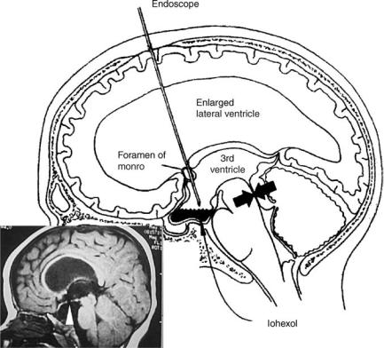
Figure 16. Third ventriculostomy is useful in patients with obstructive hydrocephalus such as observed with aqueductal stenosis (arrows). An endoscope is passed through a small hole in the skull into the frontal horn of the ventricle and navigated into the third ventricle. The floor of the third ventricle is then perforated under vision (arrow, in the inset) so as to bypass the obstruction at the aqueduct. Iohexol, a nonionic iodinated dye, is then instilled into the ventricle to demonstrate good communication between the ventricles and the subarachnoid space.
important to understand the factors that reduce shunt survival. Although the location of the proximal catheter has not been clearly shown to influence shunt survival (50,51), the presence of a small amount of fluid around the proximal catheter is associated with longer shunt survival. In a study that looked at shunt over a 11 year period, statistically significant differences were noted in shunt survival in patients with tumor versus post-hemorrhagic and aqueductal stenosis; shunts in infants and the pediatric age group survive shorter than in adults; shunt after multiple revisions survive shorter, and additional shunts placed for isolated ventricles have shorter survival (70,108). Chronic inflammatory changes of granular ependymitis often seen at the time of endoscopic shunt placement in patients with multiple revisions probably contribute to recurrent malfunction and progressive shortening of the interval between revisions as the number of surgeries increase (108).
The nature of the valve clearly influences the risk of proximal catheter malfunction. It is much lower with flow control valves (10,109). Overdrainage from the differential pressure valves pulls the choroid plexus toward the proximal catheter and may promote malfunction (55). However, the increased rate of valve malfunction in flow control devices balances out this advantage (10).
THIRD VENTRICULOSTOMY
In patients with an obstructive type of hydrocephalus, third ventriculostomy offers an alternative to shunt. The procedure involves making an opening in the relatively
thin membrane of the floor of the third ventricle. This is accomplished by passing an endoscope through the lateral ventricle and guiding it through the foramen of Munro to the floor of the third ventricle (Fig. 16). The opening allows CSF to bypass the obstruction at the level of the aqueduct or the fourth ventricle and directly enter the subarachnoid space.
Although third ventriculostomy has been recommended as a procedure of choice for obstructive hydrocephalus; data from some prospective studies have failed to show an improved cure rate (110,111). A retrospective analysis of ventriculographic versus endoscopic third ventriculostomy in 213 cases does show the superiority of the endoscopic procedure over the ventriculographic operation both in terms of reduced risk and improved survival of the procedure (112). Despite the theoretical advantages, evidence suggests that third ventriculostomy may not be effective in controlling raised intracranial pressure in all patients (112,113). Early failures in a radiologically proven case of obstructive hydrocephalus may relate to multifactorial etiology of hydrocephalus; associated absorption defects, obliteration of subarachnoid space from long-standing ventricular diltation, and unidentified infectious cause of aqeductal stenosis may be responsible. Late failures may relate to gliotic scarring over the ventriculostomy, which has been visually confirmed by endoscope in some cases. Does the ventriculostomy close from scarring, or is it a secondary response to lack of flow through the ventriculostomy due to poor absorption, therefore, a lack of gradient between the ventricle and the subarachnoid space, is unclear. In a small prospective study comparing the shunt failure rate with the failure rate of third ventriculostomy,
HYDROCEPHALUS, TOOLS FOR DIAGNOSIS AND TREATMENT OF |
15 |
no statistical difference was found between the two (12). Likewise, no controlled study has compared laser, blunt, or sharp fenestration of the floor or demonstrated usefulness of balloon diltation of the fenestration. The success rate of third ventriculostomy of 49–100%, as reported in the literature, may not be a true representative of the efficacy of third ventriculostomy (12). Evaluation after third ventriculostomy and defining success is difficult in the absence of documented reduction in ICP or improvement on neuropyschological tests. This is so because the ventricles may not reduce in size, and to and from motion through the patent fenestration may still be observed on MRI CSF flow studies even though the patient may be symptomatic. In the absence of clear evidence in literature, third ventriculostomy is often advocated for patients with obstructive hydrocephalus, and if failures occur,shunting ispreferred over repeatfenestration.
It is hoped that close collaboration between the industry and medicine will help develop ‘‘smart shunts’’ that would be able to mimic physiological CSF dynamics. These devices will possibly incorporate nanotechnology and would be superior to the presently available devices. It is likely that better understanding of CSF drainage mechanism in the future may help develop alternatives such as drugs that improve drainage of CSF through lymphatic/arachnoidal venous channels or promote proliferation of new lymphatic/arachnoidal venous channels. Until that time, it seems that shunts are the best available alternative for management of communicating hydrocephalus.
BIBLIOGRAPHY
1.Dandy WE, Blackfan KD. Internal hydrocephalus: An experimental, clinical and pathological study. Am J Dis Child 1914;30:406–482.
2.Graham P, Howman-Giles R, Johnston I, Besser M. Evaluation of CSF shunt patency by means of technetium-99m DTPA. J Neurosurg 1982;57:262–266.
3.Nulsen FE, Becker DP. Control of hydrocephalus by valveregulated shunt. J Neurosurg 1967;26:362–374.
4.Pudenz RH, Russell FE, Hurd AH, Shelden CH. Ventriculoauriculostomy; a technique for shunting cerebrospinal fluid into the right auricle; preliminary report. J Neurosurg 1957;14:171–179.
5.Nulsen FE, Spitz EB. Treatment of hydrocephalus by direct shunt from ventricle to jugular vain. Surg Forum 1951;94: 399–403.
6.Fernell E, Hagberg B, Hagberg G, von Wendt L. Epidemiology of infantile hydrocephalus in Sweden. I. Birth prevalence and general data. Acta Paediatr Scand 1986;75:975–981.
7.Bondurant CP, Jimenez DF. Epidemiology of cerebrospinal fluid shunting. Pediatr Neurosurg 1995;23:254–258; discussion 259.
8.Foltz EL, Shurtleff DB. Five-year comparative study of hydrocephalus in children with and without operation (113 Cases). J Neurosurg 1963;20:1064–1079.
9.Laurence KM, Coates S. The natural history of hydrocephalus. Detailed analysis of 182 unoperated cases. Arch Dis Child 1962;37:345–362.
10.Drake JM, Kestle JR, Milner R, Cinalli G, Boop F, Piatt J, Jr. Haines S, Schiff SJ, Cochrane DD, Steinbok P, MacNeil N. Randomized trial of cerebrospinal fluid shunt valve design in pediatric hydrocephalus. Neurosurgery 1998;43:294–303; discussion 303–295.
11.Patwardhan RV, Nanda A. Implanted ventricular shunts in the United States: The billion-dollar-a-year cost of hydrocephalus treatment. Neurosurgery 2005;56:139–144; discussion 144–135.
12.Tuli S, Alshail E, Drake J. Third ventriculostomy versus cerebrospinal fluid shunt as a first procedure in pediatric hydrocephalus. Pediatr Neurosurg 1999;30:11–15.
13.Bell WO. Cerebrospinal fluid reabsorption. A critical appraisal. 1990. Pediatr Neurosurg 1995;23:42–53.
14.Edsbagge M, Tisell M, Jacobsson L, Wikkelso C. Spinal CSF absorption in healthy individuals. Am J Physiol Regul Integr Comp Physiol 2004;287:R1450–1455.
15.Koh L, Zakharov A, Johnston MG. Integration of the subarachnoid space and lymphatics: Is it time to embrace a new concept of cerebrospinal fluid absorption? Cerebrospinal Fluid Res 2005;2:6.
16.Johnston M, Zakharov A, Papaiconomou C, Salmasi G, Armstrong D. Evidence of connections between cerebrospinal fluid and nasal lymphatic vessels in humans, non-human primates and other mammalian species. Cerebrospinal Fluid Res 2004;1:2.
17.Greitz D, Greitz T, Hindmarsh T. We need a new understanding of the reabsorption of cerebrospinal fluid—II. Acta Paediatr 1997;86:1148.
18.Marmarou A, Shulman K, LaMorgese J. Compartmental analysis of compliance and outflow resistance of the cerebrospinal fluid system. J Neurosurg 1975;43:523–534.
19.Raksin PB, Alperin N, Sivaramakrishnan A, Surapaneni S, Lichtor T. Noninvasive intracranial compliance and pressure based on dynamic magnetic resonance imaging of blood flow and cerebrospinal fluid flow: Review of principles, implementation, and other noninvasive approaches. Neurosurg Focus 2003;14:e4.
20.McAllister JP2nd, Chovan P. Neonatal hydrocephalus. Mechanisms and consequences. Neurosurg Clin N Am 1998; 9:73–93.
21.Adams RD, Fisher CM, Hakim S, Ojemann RG, Sweet WH. Symptomatic occult hydrocephalus with ‘‘normal’’ cerebrospinalfluid pressure. A treatable syndrome. N Engl J Med 1965; 273:117–126.
22.Oi S, Shimoda M, Shibata M, Honda Y, Togo K, Shinoda M, Tsugane R, Sato O. Pathophysiology of long-standing overt ventriculomegaly in adults. J Neurosurg 2000;92:933–940.
23.Di Rocco C, Pettorossi VE, Caldarelli M, Mancinelli R, Velardi F. Experimental hydrocephalus following mechanical increment of intraventricular pulse pressure. Experientia 1977;33:1470–1472.
24.Egnor M, Rosiello A, Zheng L. A model of intracranial pulsations. Pediatr Neurosurg 2001;35:284–298.
25.Egnor M, Zheng L, Rosiello A, Gutman F, Davis R. A model of pulsations in communicating hydrocephalus. Pediatr Neurosurg 2002;36:281–303.
26.Linninger AA, Tsakiris C, Zhu DC, Xenos M, Roycewicz P, Danziger Z, Penn R. Pulsatile cerebrospinal fluid dynamics in the human brain. IEEE Trans Biomed Eng 2005;52:557–565.
27.Stephensen H, Tisell M, Wikkelso C. There is no transmantle pressure gradient in communicating or noncommunicating hydrocephalus. Neurosurgery 2002;50:763–771; discussion 771–763.
28.Portnoy HD, Branch C, Castro ME. The relationship of intracranial venous pressure to hydrocephalus. Childs Nerv Syst 1994;10:29–35.
29.Marmarou A. A theoretical model and experimental evaluation of the cerebrospinal fluid system. 1973.
30.Alperin N, Lichtor T, Mazda M, Lee SH. From cerebrospinal fluid pulsation to noninvasive intracranial compliance and pressure measured by MRI flow studies. Curr Med Imaging Rev. In press.
16 HYDROCEPHALUS, TOOLS FOR DIAGNOSIS AND TREATMENT OF
31.Marmarou A, Shulman K, Rosende RM. A nonlinear analysis of the cerebrospinal fluid system and intracranial pressure dynamics. J Neurosurg 1978;48:332–344.
32.Ekstedt J. CSF hydrodynamic studies in man. 1. Method of constant pressure CSF infusion. J Neurol Neurosurg Psych 1977;40:105–119.
33.Lundkvist B, Eklund A, Kristensen B, Fagerlund M, Koskinen LO, Malm J. Cerebrospinal fluid hydrodynamics after placement of a shunt with an antisiphon device: A long-term study. J Neurosurg 2001;94:750–756.
34.Czosnyka M, Batorski L, Laniewski P, Maksymowicz W, Koszewski W, Zaworski W. A computer system for the identification of the cerebrospinal compensatory model. Acta Neurochirurgica 1990;105:112–116.
35.Borgesen SE, Gjerris F. The predictive value of conductance to outflow of CSF in normal pressure hydrocephalus. J Neurol 1982;105:65–86.
36.Marmarou A, Bergsneider M, Klinge P, Relkin N, Black PM. The value of supplemental prognostic tests for the preoperative assessment of idiopathic normal-pressure hydrocephalus. Neurosurgery 2005;57:17–28.
37.Huang TY, Chung HW, Chen MY, Giiang LH, Chin SC, Lee CS, Chen CY, Liu YJ. Supratentorial cerebrospinal fluid production rate in healthy adults: Quantification with twodimensional cine phase-contrast MR imaging with high temporal and spatial resolution. Radiology 2004;233:603–608.
38.Alperin NJ, Lee SH, Loth F, Raksin PB, Lichtor T. MRIntracranial pressure (ICP): A method to measure intracranial elastance and pressure noninvasively by means of MR imaging: Baboon and human study. Radiology 2000;217:877–885.
39.Urchuk SN, Plewes DB. MR measurements of pulsatile pressure gradients. J Magn Reson Imaging 1994;4:829–836.
40.Bird R, Stewart W, Lightfoot E. Transport Phenomena. New York: Wiley Sons; 1960.
41.Walters BC, Hoffman HJ, Hendrick EB, Humphreys RP. Cerebrospinal fluid shunt infection. Influences on initial management and subsequent outcome. J Neurosurg 1984;60: 1014– 1021.
42.Pople IK, Ettles D. The role of endoscopic choroid plexus coagulation in the management of hydrocephalus. Neurosurgery 1995;36:698–701; discussion 701–692.
43.Weiss MH, Nulsen FE, Kaufman B. Selective radionecrosis of the choroid plexus for control of experimental hydrocephalus. J Neurosurg 1972;36:270–275.
44.Aoki N. Lumboperitoneal shunt: Clinical applications, complications, and comparison with ventriculoperitoneal shunt. Neurosurgery 1990;26:998–1003; discussion 1003–1004.
45.Selman WR, Spetzler RF, Wilson CB, Grollmus JW. Percutaneous lumboperitoneal shunt: Review of 130 cases. Neurosurgery 1980;6:255–257.
46.Chumas PD, Armstrong DC, Drake JM, Kulkarni AV, Hoffman HJ, Humphreys RP, Rutka JT, Hendrick EB. Tonsillar herniation: The rule rather than the exception after lumboperitoneal shunting in the pediatric population. J Neurosurg 1993;78:568–573.
47.Payner TD, Prenger E, Berger TS, Crone KR. Acquired Chiari malformations: Incidence, diagnosis, and management. Neurosurgery 1994;34:429–434; discussion 434.
48.Ausman JI. Shunts: Which one, and why? Surg Neurol 1998;49:8–13.
49.Albright AL, Haines SJ, Taylor FH. Function of parietal and frontal shunts in childhood hydrocephalus. J Neurosurg 1988;69:883–886.
50.Bierbrauer KS, Storrs BB, McLone DG, Tomita T, Dauser R. A prospective, randomized study of shunt function and infections as a function of shunt placement. Pediatr Neurosurg 1990;16:287–291.
51.Sainte-Rose C, Piatt JH, Renier D, Pierre-Kahn A, Hirsch JF, Hoffman HJ, Humphreys RP, Hendrick EB. Mechanical complications in shunts. Pediatr Neurosurg 1991;17:2–9.
52.Pang D, Grabb PA. Accurate placement of coronal ventricular catheter using stereotactic coordinate-guided free-hand passage. Technical note. J Neurosurg 1994;80:750–755.
53.Yamamoto M, Oka K, Nagasaka S, Tomonaga M. Ventriculoscopeguided ventriculoperitoneal shunt and shunt revision. Technical note. Acta Neurochir (Wien) 1994;129:85–88.
54.Kestle JR, Drake JM, Cochrane DD, Milner R, Walker ML, Abbott R, 3rd, Boop FA. Lack of benefit of endoscopic ventriculoperitoneal shunt insertion: A multicenter randomized trial. J Neurosurg 2003;98:284–290.
55.Hakim S. Observations on the physiopathology of the CSF pulse and prevention of ventricular catheter obstruction in valve shunts. Dev Med Child Neurol Suppl 1969;20:42–48.
56.Martinez-Lage JF, Lopez F, Poza M, Hernandez M. Prevention of intraventricular hemorrhage during CSF shunt revisions by means of a flexible coagulating electrode. A preliminary report. Childs Nerv Syst 1998;14:203–206.
57.Steinbok P, Cochrane DD. Removal of adherent ventricular catheter. Pediatr Neurosurg 1992;18:167–168.
58.Whitfield PC, Guazzo EP, Pickard JD. Safe removal of retained ventricular catheters using intraluminal choroid plexus coagulation. Technical note. J Neurosurg 1995;83: 1101–1102.
59.Handler MH. A complication in removing a retained ventricular catheter using electrocautery. Pediatr Neurosurg 1996; 25:276.
60.Czosnyka M, Czosnyka Z, Whitehouse H, Pickard JD. Hydrodynamic properties of hydrocephalus shunts: United Kingdom Shunt Evaluation Laboratory. J Neurol Neurosurg Psych 1997;62:43–50.
61.Trost HA. Is there a reasonable differential indication for different hydrocephalus shunt systems? Childs Nerv Syst 1995;11:189–192.
62.Sood S, Kumar CR, Jamous M, Schuhmann MU, Ham SD, Canady AI. Pathophysiological changes in cerebrovascular distensibility in patients undergoing chronic shunt therapy. J Neurosurg 2004;100:447–453.
63.Pollack IF, Albright AL, Adelson PD. A randomized, controlled study of a programmable shunt valve versus a conventional valve for patients with hydrocephalus. Hakim-Medos Investigator Group. Neurosurgery 1999;45:1399–1408; discussion 1408–1311.
64.Aschoff A, Kremer P, Benesch C, Fruh K, Klank A, Kunze S. Overdrainage and shunt technology. A critical comparison of programmable, hydrostatic and variable-resistance valves and flow-reducing devices. Childs Nerv Syst 1995;11:193–202.
65.Drake JM, da Silva MC, Rutka JT. Functional obstruction of an antisiphon device by raised tissue capsule pressure. Neurosurgery 1993;32:137–139.
66.Fox JL, Portnoy HD, Shulte RR. Cerebrospinal fluid shunts: An experimental evaluation of flow rates and pressure values in the anti-siphon valve. Surg Neurol 1973;1:299–302.
67.Tokoro K, Chiba Y. Optimum position for an anti-siphon device in a cerebrospinal fluid shunt system. Neurosurgery 1991;29:519–525.
68.Chabbra DK, Agarwal GD, Mittal P. ‘‘Z’’ flow hydrocephalus shunts, a new approach to the problem of hysrocephalus. The rationale behind its design and the initial results of pressure monitoring after ‘‘Z’’ flow shunt implantation. Acta Neurochir (Wien) 1993;121:43–47.
69.Sekhar LN, Moossy J, Guthkelch AN. Malfunctioning ventriculoperitoneal shunts. Clinical and pathological features. J Neurosurg 1982;56:411–416.
70.Cozzens JW, Chandler JP. Increased risk of distal ventriculoperitoneal shunt obstruction associated with slit valves or
HYDROCEPHALUS, TOOLS FOR DIAGNOSIS AND TREATMENT OF |
17 |
distal slits in the peritoneal catheter. J Neurosurg 1997;87: 682–686.
71.Couldwell WT, LeMay DR, McComb JG. Experience with use of extended length peritoneal shunt catheters. J Neurosurg 1996;85:425–427.
72.Borgbjerg BM, Gjerris F, Albeck MJ, Hauerberg J, Borgesen SV. A comparison between ventriculo-peritoneal and ventriculo-atrial cerebrospinal fluid shunts in relation to rate of revision and durability. Acta Neurochir (Wien) 1998;140: 459–464; discussion 465.
73.Lam CH, Villemure JG. Comparison between ventriculoatrial and ventriculoperitoneal shunting in the adult population. Br J Neurosurg 1997;11:43–48.
74.Willison CD, Kopitnik TA, Gustafson R, Kaufman HH. Ventriculopleural shunting used as a temporary diversion. Acta Neurochir (Wien) 1992;115:67–68.
75.Ketoff JA, Klein RL, Maukkassa KF. Ventricular cholecystic shunts in children. J Pediatr Surg 1997;32:181–183.
76.Novelli PM, Reigel DH. A closer look at the ventriculogallbladder shunt for the treatment of hydrocephalus. Pediatr Neurosurg 1997;26:197–199.
77.Barami K, Sood S, Ham SD, Canady AI. Postural changes in intracranial pressure in chronically shunted patients. Pediatr Neurosurg 2000;33:64–69.
78.Bernstein RA, Hsueh W. Ventriculocholecystic shunt. A mortality report. Surg Neurol 1985;23:31–37.
79.Philips MF, Schwartz SB, Soutter AD, Sutton LN. Ventriculofemoroatrial shunt: A viable alternative for the treatment of hydrocephalus. Technical note. J Neurosurg 1997;86: 1063–1066.
80.Rengachary SS. Transdiaphragmatic ventriculoperitoneal shunting: Technical case report. Neurosurgery 1997;41: 695–697; discussion 697–698.
81.Goldblum RM, Pelley RP, O’Donell AA, Pyron D, Heggers JP. Antibodies to silicone elastomers and reactions to ventriculoperitoneal shunts. Lancet 1992;340:510–513.
82.Gower DJ, Lewis JC, Kelly DL, Jr. Sterile shunt malfunction. A scanning electron microscopic perspective. J Neurosurg 1984;61:1079–1084.
83.Snow RB, Kossovsky N. Hypersensitivity reaction associated with sterile ventriculoperitoneal shunt malfunction. Surg Neurol 1989;31:209–214.
84.Sugar O, Bailey OT. Subcutaneous reaction to silicone in ventriculoperitoneal shunts. Long-term results. J Neurosurg 1974;41:367–371.
85.Kalousdian S, Karlan MS, Williams MA. Silicone elastomer cerebrospinal fluid shunt systems. Council on Scientific Affairs, American Medical Association. Neurosurgery 1998; 42:887–892.
86.Jimenez DF, Keating R, Goodrich JT. Silicone allergy in ventriculoperitoneal shunts. Childs Nerv Syst 1994;10: 59– 63.
87.Del Bigio MR. Biological reactions to cerebrospinal fluid shunt devices: A review of the cellular pathology. Neurosurgery 1998;42:319–325; discussion 325–316.
88.Echizenya K, Satoh M, Murai H, Ueno H, Abe H, Komai T. Mineralization and biodegradation of CSF shunting systems. J Neurosurg 1987;67 :584–591.
89.Elisevich K, Mattar AG, Cheeseman F. Biodegradation of distal shunt catheters. Pediatr Neurosurg 1994;21:71–76.
90.Irving IM, Castilla P, Hall EG, Rickham PP: Tissue reaction to pure and impregnated silastic. J Pediatr Surg 1971;6:724– 729.
91.Aryan HE, Meltzer HS, Park MS, Bennett RL, Jandial R, Levy ML. Initial experience with antibiotic-impregnated silicone catheters for shunting of cerebrospinal fluid in children. Childs Nerv Syst 2005;21:56–61.
92.Govender ST, Nathoo N, van Dellen JR: Evaluation of an antibiotic-impregnated shunt system for the treatment of hydrocephalus. J Neurosurg 2003;99:831–839.
93.Fried A, Shapiro K. Subtle deterioration in shunted childhood hydrocephalus. A biomechanical and clinical profile. J Neurosurg 1986;65:211–216.
94.Watkins L, Hayward R, Andar U, Harkness W. The diagnosis of blocked cerebrospinal fluid shunts: A prospective study of referral to a paediatric neurosurgical unit. Childs Nerv Syst 1994;10:87–90.
95.Piatt JH, Jr. Physical examination of patients with cerebrospinal fluid shunts: Is there useful information in pumping the shunt? Pediatrics 1992;89:470–473.
96.Martinez-Lage JF, Poza M, Izura V. Retrograde migration of the abdominal catheter as a complication of ventriculoperitoneal shunts: The fishhook sign. Childs Nerv Syst 1993;9: 425–427.
97.Sood S, Canady AI, Ham SD. Evaluation of shunt malfunction using shunt site reservoir. Pediatr Neurosurg 2000; 32:180–186.
98.Hayden PW, Rudd TG, Shurtleff DB. Combined pressureradionuclide evaluation of suspected cerebrospinal fluid shunt malfunction: A seven-year clinical experience. Pediatrics 1980;66:679–684.
99.Sweeney LE, Thomas PS. Contrast examination of cerebrospinal fluid shunt malfunction in infancy and childhood. Pediatr Radiol 1987;17:177–183.
100.Vernet O, Farmer JP, Lambert R, Montes JL. Radionuclide shuntogram: Adjunct to manage hydrocephalic patients. J Nucl Med 1996;37:406–410.
101.Savoiardo M, Solero CL, Passerini A, Migliavacca F. Determination of cerebrospinal fluid shunt function with watersoluble contrast medium. J Neurosurg 1978;49:398–407.
102.Kadowaki C, Hara M, Numoto M, Takeuchi K, Saito I. CSF shunt physics: factors influencing inshunt CSF flow. Childs Nerv Syst 1995;11:203–206.
103.Czosnyka M, Whitehouse H, Smielewski P, Simac S, Pickard JD. Testing of cerebrospinal compensatory reserve in shunted and non-shunted patients: A guide to interpretation based on an observational study. J Neurol Neurosurg Psych 1996;60:549–558.
104.Morgan MK, Johnston IH, Spittaler PJ. A ventricular infusion technique for the evaluation of treated and untreated hydrocephalus. Neurosurgery 1991;29:832–836; discussion 836–837.
105.Fouyas IP, Casey AT, Thompson D, Harkness WF, Hayward RD. Use of intracranial pressure monitoring in the management of childhood hydrocephalus and shunt-related problems. Neurosurgery 1996;38:726–731; discussion 731–722.
106.Woodford J, Saunders RL, Sachs E, Jr. Shunt system patency testing by lumbar infusion. J Neurosurg 1976;45:60–65.
107.Cosman ER, Zervas NT, Chapman PH, Cosman BJ, Arnold MA. A telemetric pressure sensor for ventricular shunt systems. Surg Neurol 1979;11:287–294.
108.Miyake H, Ohta T, Kajimoto Y, Matsukawa M. A new ventriculoperitoneal shunt with a telemetric intracranial pressure sensor: Clinical experience in 94 patients with hydrocephalus. Neurosurgery 1997;40:931–935.
109.Lazareff JA, Peacock W, Holly L, Ver Halen J, Wong A, Olmstead C. Multiple shunt failures: An analysis of relevant factors. Childs Nerv Syst 1998;14:271–275.
110.Decq P, Barat JL, Duplessis E, Leguerinel C, Gendrault P, Keravel Y. Shunt failure in adult hydrocephalus: Flow-con- trolled shunt versus differential pressure shunts–a cooperative study in 289 patients. Surg Neurol 1995;43:333–339.
111.Garton HJ, Kestle JR, Cochrane DD, Steinbok P. A costeffectiveness analysis of endoscopic third ventriculostomy. Neurosurgery 2002;51:69–77; discussion 77–68.