

The ABC’s of AutoLISP by George Omura
Understanding How a Program Works
Up until now, you have been dealing with very simple AutoLISP expressions that perform simple tasks such as adding or multiplying numbers or setting system variables. Now that you know how to save AutoLISP code in a file, you can begin to create larger programs. The box program is really nothing more than a collection of expressions that are designed to work together to obtain specific results. In this section, we will examine the Box program to see how it works.
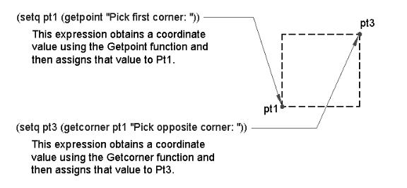
The Box program draws the box by first obtaining a corner point using Getpoint:
(setq pt1 (getpoint pt1 "Pick first corner: ''))
The user will see only the prompt portion of this expression:
Pick first corner:
Next, the opposite corner point is obtained using Getcorner (see Figure 2.3).
(setq pt3 (getcorner pt1 "Pick opposite corner: ''))
Again, the user only sees the prompt string:
Pick opposite corner:
Figure 2.3: The workings of the box program
You may recall that Getcorner will display a window as the user move the cursor. In this box program, this window allows the user to visually see the shape of the box before the opposite corner is selected (see figure 2.2). Once the
33
Copyright © 2001 George Omura,,World rights reserved
The ABC’s of AutoLISP by George Omura
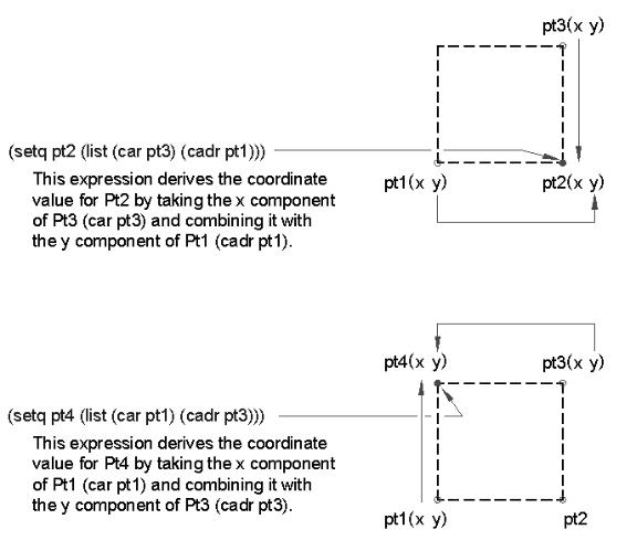
second point is selected, the Box program uses the point coordinates of the first and opposite corners to derive the other two corners of the box. This is done by manipulating the known coordinates using Car, Cadr, and List (see Figure 2.4).
pt2 (list (car pt3) (cadr pt1)))
pt4 (list (car pt1) (cadr pt3)))
Figure 2.4: Using Car, Cadr, and List to derive the remaining box corners
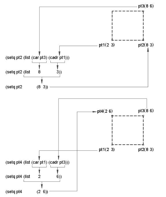
Pt2 is derived by combining the X component of Pt3 with the Y component of Pt1. Pt 4 is derived from combining the X component of Pt1 with the Y component of Pt3 (see figure 2.5).
34
Copyright © 2001 George Omura,,World rights reserved
The ABC’s of AutoLISP by George Omura
Figure 2.5: Using Car and Cadr to derive Pt2 and Pt4
35
Copyright © 2001 George Omura,,World rights reserved
The ABC’s of AutoLISP by George Omura
Using AutoCAD Commands in AutoLISP
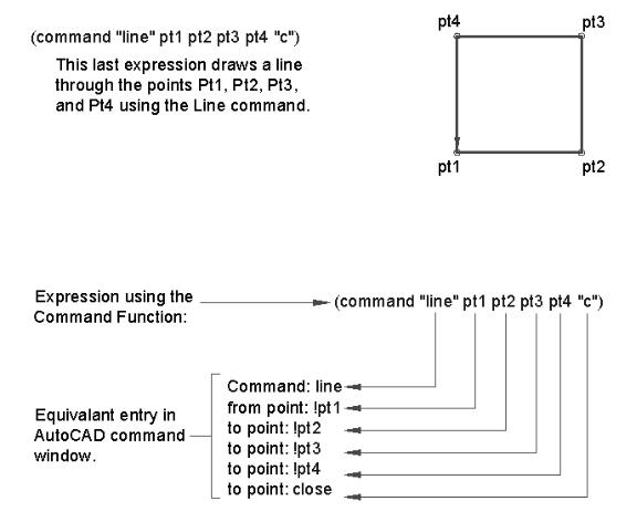
The last line in the box program:
(command "line'' pt1 pt2 pt3 pt4 "c'')
shows you how AutoCAD commands are used in an AutoLISP expression (see figure 2.6). Command is an AutoLISP function that calls standard AutoCAD commands. The command to be called following the Command function is enclosed in quotation marks. Anything in quotation marks after the Command function is treated as keyboard input. Variables follow, but unlike accessing variables from the command prompt, they do not have to be preceded by an exclamation point. The C enclosed in quotation marks at the end of the expression indicates a Close option for the Line command (see Figure 2.7.
Figure 2.6: Using AutoCAD commands in a function.
Figure 2.7: Variables help move information from one expression to another.
36
Copyright © 2001 George Omura,,World rights reserved