

The ABC’s of AutoLISP by George Omura
Chapter 8: Interacting with AutoLISP
Introduction |
Creating a Function to Handle Defaults |
Reading and Writing to the Screen |
Dealing with Aborted Functions |
Reading the Cursor Dynamically |
Using the *error* Function |
Writing Text to the Status and Menu Areas |
Organizing Code to Reduce Errors |
Calling Menus from AutoLISP |
Debugging Programs |
Drawing Temporary Images on the Drawing Area |
Common Programming Errors |
Using Defaults in a Program |
Using Variables as Debugging Tools |
Adding Default Responses to your Program |
Conclusion |
Introduction
AutoLISP offers a number of ways to interact with AutoCAD and the user. You have already seen how AutoLISP can control system variables through the setvar and getvar functions and you have seen the various ways your programs can obtain information from the user through the get functions. You can also control the display of menus, status and coordinate lines, graphic and text screens, and even the drawing area. By giving you control over the display, you can enhance the way your programs interact with the user.
When writing your program, consideration should be made as to how the program will act under various conditions. In this chapter, you will explore some of the ways you can exploit AutoLISP and AutoCAD features to make your programs more responsive to the user.
Reading and Writing to the Screen
There are many functions that will allow you to write prompts to the prompt line. But you are not limited to control of the prompt. Several functions are available that allow you to both read and write to other parts of the AutoCAD drawing editor. In this section, you will examine these functions.
Reading the Cursor Dynamically
In chapter 3 you used a function called RXY. This function reads the cursor location relative to a reference point and writes the relative coordinate directly to the coordinate readout. This is done dynamically as the cursor moves. The function that allows this to occur is the grread function. Grread's syntax is:
162
Copyright © 2001 George Omura,,World rights reserved

The ABC’s of AutoLISP by George Omura
(grread [optional track argument])
Grread is a general input device reading function. It reads input from the keyboard, buttons on your pointing device, or the cursor location. Grread returns a list of two elements:
([integer][coordinate list or integer])
The first element is a code representing the type of input received. The second element is either an integer or list depending on whether a point has been input or a keyboard or pointing device button has been depressed. Table shows a list of codes for the first element of the list returned by grread:
Input Code
(2 [ASCII code])
(3 [coordinate])
(4 [cell #])
(5 [coordinate])
(6 [button #])
(7 [box #])
(7-10 [box #])
(11 [box #])
(12 [coordinate])
(13 [menu cell #])
Meaning
keyboard pressed. The second element of the list will be an integer representing the ASCII code of the key character pressed.
Cursor location picked. The second element of the list will be a coordinate list.
Screen menu cell picked. The second element of the list will be an integer representing the cell number. The cells are numbered from top to bottom.
Dynamic cursor mode. The second element of the list will be a coordinate list. This code is returned only if a non-nil argument is supplied to the grread function.
Button on pointing device pressed. The second element of the list will be an integer representing the button number.
Tablet1 menu item selected. The second element of the list will be an integer representing the tablet item box number.
Tablet menu item selected. 7 equals tablet1 menu group, 8 equals tabalet2 menu group and so on. The second element of the list will be an integer representing the tablet item box number.
Aux1 menu item selected. The second element of the list will be an integer representing the tablet item box number.
If two grread functions are used in sequence, and the first returns a code 6, the second grread will return a code 12 and its second element will be the coordinate of the cursor at the time the pointing device button was picked.
Screen menu item picked using keyboard input. The second element of the list will be the menu cell number.
Open a new AutoCAD file and turn on the snap mode. Enter the following at the AutoCAD command prompt:
(grread)
Now pick a point near the center of the screen using our mouse or digitizer puck. You will get a list similar to the following:
163
Copyright © 2001 George Omura,,World rights reserved
The ABC’s of AutoLISP by George Omura
(3 (7.0 5.0 0.0))
The first element of the list is the integer 3. this tells us that the pick button on the pointing device was entered. The second element is a coordinate list showing the coordinate that was picked.
lets look at the expression in the RXY function that uses grread to read the cursor dynamically:
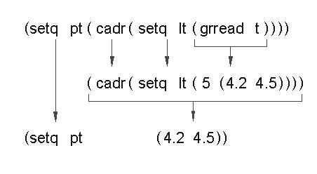
(setq pt (cadr (setq lt (grread t))))
The t argument tells grread to read the cursor location dynamically, that is, read it regardless of whether a button has been pushed or not. By using the T option, grread reads the cursor location even as it moves. The value from grread is assigned to the symbols lt for later processing. This value in turn is applied to cadr to obtain the coordinate list from grread. Finally, the coordinate list is assigned to the symbol pt (see figure 8.1).
Figure 8.1: The evaluation of the grread expression
Once the coordinate is read by grread in the above expression, it is processed by the following set of expressions:
(if (= (car lt) 5) (progn
(setq x (strcat
(rtos (- (car pt) (car lpt1))) " x " (rtos (- (cadr pt) (cadr lpt1))) " SI= " (rtos (*(- (car pt) (car lpt1))
(- (cadr pt) (cadr lpt1))
164
Copyright © 2001 George Omura,,World rights reserved
The ABC’s of AutoLISP by George Omura
)
2 2)
)
)
(grtext -2 x)
)
)
This set of expressions takes the x and y components of the point pt and subtracts them from the x and y components of the reference point lpt1, which is selected earlier by the user. It then multiplies the remaining x and y values together to get the area of the rectangle formed by these two points. Finally, these values are turned into strings that can be sent to the screen.
First, the if expression tests to see if the code gotten from grread is 5. This checks to see if the coordinate was derived from the cursor in a drag mode.
(if (= (car lt) 5)(progn
Remember that lt is the list from the grread expression so the car of lt is its first element, the input code.
The next line is the outer most nest of an expression that combines a set of strings together into one string using strcat:
(setq x (strcat
This is followed by an expression that subtracts the x component of lpt1, our reference point, from the x of the current point pt:
(rtos (- (car pt) (car lpt1))) " x "
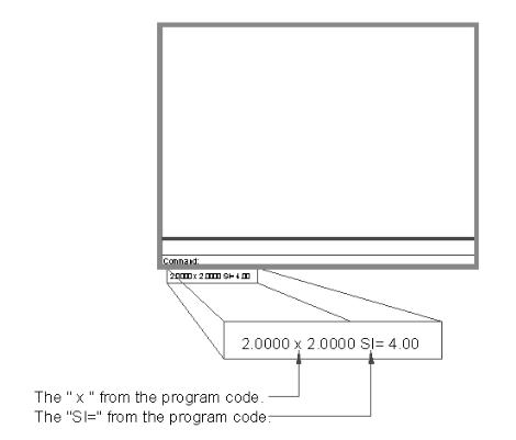
The resulting difference is converted into a string by rtos. The " x " element in this expression is the x that appears between the x and y value in the coordinate readout (see Figure 8.2).
The next expression subtracts the y component of lpt1 from the y of the current point pt then converts the resulting difference into a string:
(rtos (- (cadr pt) (cadr lpt1))) " SI= "
The " SI= " at the end of this line is the SI= that appears after the coordinate list in the coordinate readout.
165
Copyright © 2001 George Omura,,World rights reserved
The ABC’s of AutoLISP by George Omura
The next two expressions multiplies x and y value differences to get the area of the rectangle represented by lpt1 and pt:
(rtos (*(- (car pt) (car lpt1))
(- (cadr pt) (cadr lpt1))
)
2 2)
)
)
The 2 2 in the fourth line down are the unit style and precision arguments to the rtos function.
Figure 8.2: The elements of the coordinate readout
166
Copyright © 2001 George Omura,,World rights reserved