


The ABC’s of AutoLISP by George Omura
8.At the Opposite corner prompt, move the cursor and note how the coordinate readout responds. If you move the cursor to the first point you picked, the coordinate readout will list 0,0 telling you that you are a relative distance of 0,0 from the first corner.
9.Now move the cursor until the coordinate readout lists 5.0000,5.0000 then pick that point. You have drawn a box exactly 5 units in the x axis by 5 units in the y axis.
(defun getinfo ()
(setq pt1 (getpoint "Pick first corner: "))
(princ "Pick opposite corner: ") (setq pt3 (rxy))
)
(defun procinfo ()
(setq pt2 (list (car pt3) (cadr pt1))) (setq pt4 (list (car pt1) (cadr pt3)))
)
(defun output ()
(command "pline" pt1 pt2 pt3 pt4 "c" )
)
(defun C:BOX1 (/ pt1 pt2 pt3 pt4) (getinfo)
(procinfo)
(output)
)
Figure 3.4: The revised Box1.lsp file
In the above exercise, after you pick the first corner of the box, the window no longer appears. Instead, the status line changes to display the height and width of you box dynamically as you move the cursor. It also displays the square inch area of that height and width. By altering a function of the main C:BOX1 program, you have added a new features to it. Of course, you had to do the work of creating Rxy.lsp but Rxy.lsp can also be used to dynamically display relative X Y coordinates in any command that reads point values.
Reusing Functions
You have seen that by breaking the box program into independent functions, you can add other functions to your program to alter the way the program works. In the following section, you will create two more programs, one to draw a 3D rectangle, and one to draw a wedge, using those same functions from the box program.
55
Copyright © 2001 George Omura,,World rights reserved
The ABC’s of AutoLISP by George Omura
Creating an 3D Box program
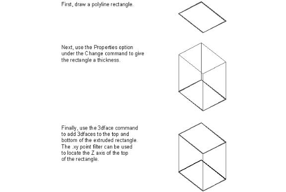
To create a 3D box from a rectangle, all you really need to do is extrude your rectangle in the Z axis then add a 3dface to the top and bottom of the box. Extruding the box can be accomplished using the Change command. Figure 3.5 shows how this would be done with standard AutoCAD commands.
Figure 3.5: Drawing a three-dimensional box manually
Your box program also needs a way to prompt the user for a height. We can accomplish these things by creating a modified version of the C:BOX1 main program. Figure 3.6 shows such a program.
56
Copyright © 2001 George Omura,,World rights reserved

The ABC’s of AutoLISP by George Omura
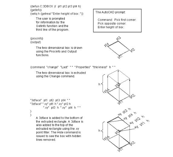
(defun C:3DBOX (/ pt1 pt2 pt3 pt4 h) (getinfo)
(setq h (getreal "Enter height of box: ")) (procinfo)
(output)
(command "change" "L" "" "P" "th" h "" "3dface" pt1 pt2 pt3 pt4 "" "3dface" ".xy" pt1 h ".xy" pt2 h ".xy" pt3 h ".xy" pt4 h ""
)
)
Figure 3.6: A program to draw a 3D box.
In the following exercise, you will add the 3D box program to the Box1.lsp file then run C:3DBOX.
1.Exit AutoCAD temporarily either by using the AutoCAD Shell command or by using the End command to exit AutoCAD entirely.
2.Open the box1.lsp file again and add the program listed in figure 3.6 to the file. Your Box1.lsp file should look like figure 3.7.
3.Return to the Chapt3 AutoCAD file.
4.Load Box1.lsp again. If you had to Exit AutoCAD to edit Box1.lsp, Load Rxy.lsp also.
5.Start the C:3DBOX program by entering 3dbox at the command prompt.
6.At the Pick first corner prompt, pick a point near the coordinate 2,3.
7.At the Pick opposite corner prompt, move the cursor until the coordinate readout lists 7.0000,5.0000 then pick that point.
8.At the Enter height prompt, enter 6. A box appears.
9.Issue the Vpoint command and at the prompt:
Rotate/<View point> <0.0000,0.0000,1.0000>:
10.Enter -1,-1,1. Now you can see that the box is actually a 3d box.
11.Issue the Hide command. The box appears as a solid object.
57
Copyright © 2001 George Omura,,World rights reserved

The ABC’s of AutoLISP by George Omura
(defun getinfo ()
(setq pt1 (getpoint "Pick first corner: ")) (princ "Pick opposite corner: ")
(setq pt3 (rxy))
)
(defun procinfo ()
(setq pt2 (list (car pt3) (cadr pt1))) (setq pt4 (list (car pt1) (cadr pt3)))
)
(defun output ()
(command "pline" pt1 pt2 pt3 pt4 "c" )
)
(defun C:BOX1 (/ pt1 pt2 pt3 pt4) (getinfo)
(procinfo)
(output)
)
(defun C:3DBOX (/ pt1 pt2 pt3 pt4 h) (getinfo)
(setq h (getreal "Enter height of box: ")) (procinfo)
(output)
(command "change" "L" "" "P" "th" h "" "3dface" pt1 pt2 pt3 pt4 "" "3dface" ".xy" pt1 h ".xy" pt2 h ".xy" pt3 h ".xy" pt4 h ""
)
)
Figure 3.7: The Box1.lsp file with the C:3DBOX program added.
In the C:3DBOX program, a line is added to obtain height information.
(setq h (getreal "Enter height of box: "))
In most cases, it is impractical to try to enter a 3D point value using a cursor, though it can be done. We use the Getreal function here to allow the input of a real value for the height since this is the simplest route to obtain the height information.
58
Copyright © 2001 George Omura,,World rights reserved
The ABC’s of AutoLISP by George Omura
To actually draw the box, other AutoCAD commands have been added to give the box a third dimension:
(command "change" "L" "" "P" "th" h "" "3dface" pt1 pt2 pt3 pt4 ""
"3dface" ".xy" pt1 h ".xy" pt2 h ".xy" pt3 h ".xy" pt4 h ""
)
This expression issues several AutoCAD commands to turn the simple rectangle drawn by the Output function into a 3 dimensional box. the first line changes the thickness of the box previously drawn by the Output function. The second line draws a 3dface at the base of the box to close the bottom of the box. The third and fourth lines draw a 3dface at the top of the box by using the .xy point filter to designate the x and y coordinate of each corner, then entering the Z coordinate using the H variable.
59
Copyright © 2001 George Omura,,World rights reserved
The ABC’s of AutoLISP by George Omura
Figure 3.8: A 3D box using the C:3DBOX program
You may have noticed that although you added the program C:3DBOX to the Box1.lsp file, you still called up the program by entering its name, 3DBOX. We should emphasize here that AutoLISP files are only use as the vessel to hold your program code. AutoLISP makes no connection between the program name and the name of the file that holds the program. You could have called Box1.lsp by another name like Myprogm.lsp or Mybox.lsp, and the programs would still run the same. Of course, you would have to give the appropriate name when loading the file.
60
Copyright © 2001 George Omura,,World rights reserved