

The ABC’s of AutoLISP by George Omura
The syntax for polar is:
(polar [point value][angle in radians][distance])
Polar is used to find relative point locations. It requires a point value as its first argument followed by an angle and distance value. The new point value is calculated by applying the angle and distance to the point value supplied. This is similar to describing a relative location in AutoCAD using the at sign. For example, to describe a relative location of .25 units at 90 degrees from the last point entered you would enter the following in AutoCAD:
@.25<90
The same relative location would look like the following using the polar function:
(setq pt1 (getvar "lastpoint"))
(polar pt1 1.5708 .25)
The first expression in this example uses the getvar function to obtain the last point selected. Setq then assigns that point to the variable pt1. Polar is used in the next line to find a point that is 1.5708 radians (45 degrees) and 2 units away from the lastpoint.
The last several lines of the Break2 program use all the point variables to first break the two lines then draw the joining lines between them.
(command "break" pt1 pt2 "break" pt3 pt4 "line" pt1 pt3 "" "line" pt2 pt4 ""
)
)
In the Break2 program, you could have used the getdist and getangle functions but to do so would mean including an additional prompt. By using the combination of the perpend osnap mode along with the getpoint function, you establishes a point value from which both the angle and distance value is derived. In general, if you know that you will need to gather both distance and angle information, it is better to establish coordinate variables first then derive angles and distances from those coordinates using the distance and angle functions.
Using Trigonometry to Solve a Problem
The Break2 function is relatively simple as far as its manipulation of data is concerned. But at times, you will need to enlist the aid of some basic trigonometric functions to solve problems. Suppose you want a function that will cut a
123
Copyright © 2001 George Omura,,World rights reserved
The ABC’s of AutoLISP by George Omura
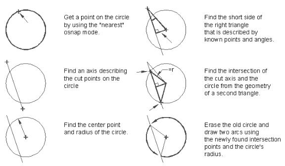
circle along an axis defined by the user. Figure 6.9 shows a sketch along with a written description of a program that does this.
Figure 6.9: Sketch of circle cutting program.
This program makes use of the Pythagorean Theorem as well as the Sine trigonometric function as you will see in the next section.
Gathering Information
Before a problem can be solved, you must first gather all the known factors affecting the problem. The program you will explore next will give an example of how you might go about your information gathering.
Exit AutoCAD and open an AutoLISP file called Cutcr.lsp. Carefully copy the program in figure 6.10 into this file. Save and exit the Cutcr.lsp file then start AutoCAD and open the Chapt6 file again. Load the Ctcr.lsp fine then do the following:
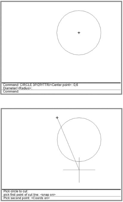
1.Erase everything on the screen then draw a circle with its center at point 8,6 and a with a radius of 3 units (see figure 6.11).
2.Enter cutcr at the command prompt to start the C:CUTCR program.
124
Copyright © 2001 George Omura,,World rights reserved

The ABC’s of AutoLISP by George Omura
3 At the prompt:
Pick circle to cut:
pick the circle you just drew. 4. At the next prompt:
Pick first point of cut line:
pick a point at coordinate 5,9. 5. At the prompt:
Pick second point:
pick a point at coordinate 8,2.
The circle is cut into two arcs along the axis represented by the two points you picked (see figure6.12).
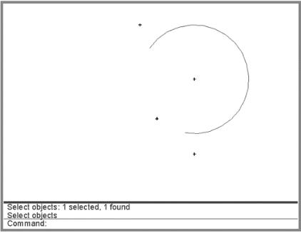
6. Use the erase command to erase the left half of the circle. You can now see that the circle has been cut (see figure 6.13).
;Program to cut a circle into two arcs -- Cutcr.lsp |
|
(defun C:CUTCR (/ cpt1 lpt1 lpt2 cent rad1 ang1 |
|
dst1 dst2 cord ang2 wkpt cpt2 cpt3) |
|
(setvar "osmode" 512) |
;osnap to nearest |
(setq cpt1 (getpoint "\nPick circle to cut: ")) |
;find point on circle |
(setvar "osmode" 0) |
;osnap to none |
(setq lpt1 (getpoint "\nPick first point of cut line: ")) ;1st point of cut |
|
(setq lpt2 (getpoint lpt1 "\nPick second point: ")) |
;2nd point of cut |
(setq cent (osnap cpt1 "center")) |
;find center pt |
(setq rad1 (distance cpt1 cent)) |
;find radius of circle |
(setq ang1 (- (angle lpt1 cent)(angle lpt1 lpt2))) |
;find difference of angles |
(setq dst1 (distance lpt1 cent)) |
;find dist.lpt1 to cent |
(setq dst2 (* dst1 (sin ang1))) |
;find side of triangle |
(setq cord (sqrt(-(* rad1 rad1)(* dst2 dst2)))) |
;find half cord |
(setq ang2 (- (angle lpt1 lpt2) 1.57)) |
;find perpend angle |
(setq wkpt (polar cent ang2 dst2)) |
;find workpoint |
(setq cpt2 (polar wkpt (angle lpt1 lpt2) cord)) |
;find first intersect |
(setq cpt3 (polar wkpt (angle lpt2 lpt1) cord)) |
;find second intersect |
(command "erase" cpt1 "" |
;erase circle |
"arc" "c" cent cpt2 cpt3 |
;draw first circle seg. |
"arc" "c" cent cpt3 cpt2 |
;draw second circle seg. |
) |
;close command funct. |
) |
;close defun |
Figure 6.10: The circle cut program
125
Copyright © 2001 George Omura,,World rights reserved
The ABC’s of AutoLISP by George Omura
Figure 6.11: The circle drawn in AutoCAD
Figure 6.12: Drawing the cut axis.
126
Copyright © 2001 George Omura,,World rights reserved
The ABC’s of AutoLISP by George Omura
Figure 6.13: Erasing one part of the circle after it has been cut.
The first three expressions in the program after the defun functions and its arguments obtain a point on the circle:
(setvar "osmode" 512)
(setq cpt1 (getpoint "\nPick circle to cut: "))
(setvar "osmode" 0)
The setvar function sets osnap to the nearest mode then the user is prompted to pick the circle to cut. This point is stored as cpt1. The osnap mode ensures that the point picked is exactly on the circle. Later, this point will be used to both erase the circle and to find the circles center. The next function sets osnap back to none.
The next two lines prompt the user to select the points that define the axis along which the circle is to be cut:
(setq lpt1 (getpoint "\npick first point of cut line: "))
(setq lpt2 (getpoint lpt1 "\nPick second point: "))
The getpoint function is used in both these expressions to obtain the endpoints of the cut axis. These endpoints are stored as lpt1 and lpt2.
The next expression uses a new function called osnap:
127
Copyright © 2001 George Omura,,World rights reserved