

The ABC’s of AutoLISP by George Omura
Pick vertex location:
Pick the square polyline at the coordinate 10,6. The box disappears and a new box is drawn with an additional vertex at the point you picked.
This program reduces into one step a process than normally takes seven steps through the Pedit command. Lets see how it works in detail.
First, an object and a point are gotten using the entsel function:
(defun C:ADDVECT (/ pEnt VecLst Newpt int NewVec type)
(setq pEnt (entsel "Pick vector location: "))
As you may recall, entsel pauses the program's processing and prompts the user to select an object. Once a user responds, a list of two elements is returned with the object name and the coordinate used to pick the object.
The next line uses a user defined function, getvec, to create a new list containing only the vertex coordinates from the polyline object picked. This list of vertices is assigned to the variable VecLst.
(setq VecLst (getvec (car pEnt)))
We saw earlier how getvec works. It returns a list of polyline vertices. In the above expression, the list of vertices is assigned to the VecLst variable.
The next line obtains the associated value of the 70 group code from the polyline. The 70 group code identifies the type of polyline it is, whether it is closed, curve-fit, spline curved, etc. See Appendix for a full list of the 70 group code options.
(setq ptyp (assoc 70 (entget (car pEnt))))
this information will be used at the end of the program to determine how the polyline is redrawn.
The next line used the osnap function to establish a point exactly on the polyline.
(setq Newpt (osnap (cadr pEnt) "nearest"))
Here, the coordinate from the entsel function used earlier is applied to the osnap "nearest" function to obtain a new point. This new point is exactly on the polyline.
Defining a New Polyline
The while expression that follows builds a new list of vertices from which a new polyline will be drawn. This list is actually a copy of the list created by our user defined function Getvec with the new point added in the appropriate place.
The test expression in the while expression tests to see if the end of the list VecLst has been reached:
245
Copyright © 2001 George Omura,,World rights reserved
The ABC’s of AutoLISP by George Omura
(while (cadr VecLst)
Next, the first element of Veclst is added to a list called NewVec:
(setq NewVec
(append NewVec (list (car VecLst)))
)
This expression is basically just copies the first element of the original vertex list to a new list NewVec.
The next set of expressions tests to see if our new vertex newpt lies between the first two point of the vertex list:
(setq int
(btwn (car VecLst) newpt (Cadr VecLst))
)
Another user-defined function is used to actually perform the test. This function is called btwn and it tests to see if one coordinate lies between two others. If Btwn does find that Newpt lies between the first and second point of VecLst, then Btwn returns the value of Newpt. Otherwise Btwn returns nil.
If the btwn test function returns a coordinate, the next expression adds the new vertex to the NewVec list.
(if int
(setq NewVec (append NewVec (list int)))
)
Finally, the first element of the vertex list is removed and the whole process is repeated.
(setq VecLst (cdr VecLst))
);end while
Once the while loop is done, VecLst is a list of one element. That last element is added to the NewVec list:
(setq NewVec (append NewVec (list (car VecLst))))
Drawing the new Polyline
The last several lines erase the old polyline and redraw it using the new vertex list. First the old line is erased:
(command "erase" (car pEnt) "")
246
Copyright © 2001 George Omura,,World rights reserved
The ABC’s of AutoLISP by George Omura
Then the pline command is issued:
(command "pline")
Next, the foreach function is used to input the vertices from the NewVec list to the Pline command:
(foreach n NewVec (command n))
You may recall that foreach is a function that reads each element from a list and applies that element to a variable. That variable is then used in an expression. The expression is evaluated until all the elements of the list have been evaluated in the expression. In this case, each vertex from the NewVec list is applied to a command function which supplies the vertex coordinate to the pline command issued in the previous expression.
Once foreach has completed evaluating every element of the NewVec list, the last expression ends the Pline command:
(if (= (cdr Ptyp) 1)
(command "close")
(command "")
)
)
The if conditional expression tests to see if the polyline is closed or not. If it is, then it enter the word "close" to close the polyline. If not, then an enter is issued. You may recall that in the first part of the program, the 70 group code sublist was extracted from the polyline property list. This sublist was assigned to the variable ptyp. Here, ptyp is tested to see if its code value is 1. If it is 1, this means that the polyline is closed thereby causing the if expression to evaluate the (command "close") expression. If this expression is left off, the new polyline box would have only three sides.
Testing for Polyline Types
In the last expression above, you got a glimpse of a special concern when dealing with polylines. There are really several types of polylines which must all be handled differently. The Addvect program will only function properly when used on simple polylines made up of line segments. Polylines that are curve-fitted or splined will contain extra vertices that are not actually part of the drawn polyline. these extra vertices are used as control points in defining curves and splines.
Fortunately, the 70 group codes enable you to determine what type of vertex you are dealing with. In the program above, we used the 70 group code only to determine whether the polyline is closed or not but other conditions can be tested for. You could include a test for a spline vertex by comparing the 70 group code value of a vertex to the value 16. If it is 16, the value for a spline frame control point, then you know not to include the vertex in your vertex list. We won't try to give you examples here as we our space is limited. However, you may want to refer to Appendix for more details on the group codes.
247
Copyright © 2001 George Omura,,World rights reserved
The ABC’s of AutoLISP by George Omura
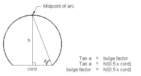
How Arcs are Described in Polylines
Arcs in polylines are described using a bulge factor and two vertices. You can think of the bulge factor as the tangent of the angle described by chord of the arc and a line drawn from one end of the arc to the arc's midpoint (see figure 11.5).
Figure 11.5: The arc bulge factor
From this relationship, the following formula is derived:
bulge = h / 0.5 cord = 2h/cord
We can derive the geometry of the arc from these simple relationships. Figure 11.6 shows how we can derive the arcs angle from the bulge factor. We don't give an example of a program to edit arcs in a polyline. Such a task could take a chapter in itself since it can be quite involved. Also, you may not find a need for such a capability at this point. However, should you find a need, we have given you the basics to build your own program to accomplish the task.
248
Copyright © 2001 George Omura,,World rights reserved