


The ABC’s of AutoLISP by George Omura
A Sample Program Using Getdist
At times, you may need to find the distance between two points in a format other than the current unit style. Figure 4.2 lists a function that displays distances in decimal feet, a common engineering system of measure that AutoCAD does not directly support in release 10.
;Function to get distance in decimal feet -- Decft.lsp------------------------
(defun decft (/ dst1 dst1s)
(setq dst1 (getdist "Pick first point or enter distance: ")) ;get distance (setq dst1s (rtos (/ dst1 12.0) 2 4)) ;convert real value to string (terpri) ;advance prompt one line
(strcat dst1s " ft.") ;return string plus "ft."
)
Figure 4.2: A program to display decimal feet
1.Exit AutoCAD by using the End command and open an AutoLISP file called Decft.lsp
2.Copy the file listed in Figure 4.1 into the Decft.lsp file. When you are done, and you are certain you have corrected all transcription errors, close the file.
3.Open an AutoCAD file called Chapt4. Be sure add the = sign at the end of the file name.
4.Use the Setup option on the main menu to set up you drawing using the Architectural unit style at a scale of 1/8 inch equals 1 foot. Select a sheet size of 11 by 17.
5.Set the snap distance to 12 by 12 and turn on the Dynamic coordinate readout.
6.Load the Decft.lsp file.
7.Enter Decft at the Command prompt. The following prompt appears:
Pick first point or enter distance:
8. Pick a point at the coordinate 17'-0",9'-0". The next prompt appears:
Second point:
9. Pick a point at the coordinate 100'-0",70'-0". The prompt displays the distance 103.0049 ft.
The first line defines the function. The second line obtains the distance using the Getdist function.
74
Copyright © 2001 George Omura,,World rights reserved
The ABC’s of AutoLISP by George Omura
(setq dst1 (getdist "Pick first point: "))
The third line uses the Rtos function to convert the distance value from a real to a string (see Chapter ).
(setq dst1s (rtos (/ dst1 12.0) 2 4))
This conversion is necessary because we want to append the string "ft" to the numeric distance value obtained from getdist. The fourth line enters a return to the prompt line. The last line combines the string distance value with the string "ft.".
(terpri)
(strcat dst1s " ft")
AutoLISP will return the value of the last expression evaluated so the result of combining the distance with "ft" is displayed on the command prompt. The result value could be assigned to a variable for further processing as in the following line:
(setq dist2s (decft))
In this simple expression, the final value returned by Decft is assigned to the variable Dist2s.
How to Get Angle Values
When you are manipulating drawings with AutoLISP, you will eventually need to obtain angular information. AutoLISP provides the Getangle and Getorient functions for this purpose. These functions determine angles based on point input. This means that two point values are required before these functions will complete their execution. Getangle and Getorient will accept keyboard input of relative or absolute coordinates or cursor input to allow angle selection from the graphic screen. Getangle and Getorient always return angles in radians, regardless of the current AutoCAD Units settings. So even if you are using Architectural units, Getangle and Getorient will return a distance in radians (see chapter___ for a discussion of radian to degree conversion).
Using Getangle and Getorient
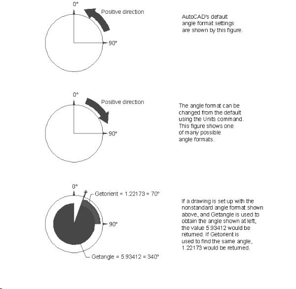
The difference between Getangle and Getorient is that Getangle will return an angle value relative to the current Unit setting for the 0 angle while Getorient will return an angle based on the "standard" 0 angle setting. For example, the default or "standard" orientation for 0 degrees is a direction from left to right but you can use the Units command or the Angbase or Angdir system variables to make 0 degrees a vertical direction. If a drawing is set up with 0 degrees being a direction from bottom to top, Getangle will return a value relative to this orientation while Getorient will return a value based on the "standard" orientation regardless of the Units, Angbase, or Angdir settings. Figure 4.3 illustrates these differences.
75
Copyright © 2001 George Omura,,World rights reserved
The ABC’s of AutoLISP by George Omura
Figure 4.3: Comparing Getorient and Getangle
NOTE THAT Getorient ignores the angle direction setting. Even though the hypothetical setting uses a clockwise direction for the positive angle direction, getorient still returns angles using the counter-clockwise direction for positive angle.
The syntax for Getangle and Getorient are:
(getangle [optional point value] [optional prompt string])
(getorient [optional point value] [optional prompt string])
76
Copyright © 2001 George Omura,,World rights reserved
The ABC’s of AutoLISP by George Omura
You can optionally supply one or two arguments to these functions. These arguments can be either string values which will be used as prompts to user when the program is run, or point values indicating a position from which to measure the angle.
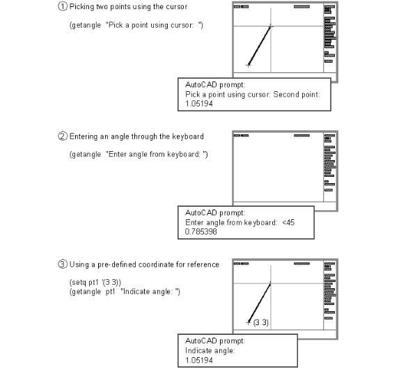
Getangle and getorient accept three methods of input. These methods are similar to those offered by getdist. In the first method, you can enter two points.
1. Enter the following:
(setq ang1 (getangle "Pick a point or enter angle: "))
2. Pick a point at coordinate 3,3. A rubberbanding line appears from the picked point and you get the prompt:
Second point:
3. Pick another point at coordinate 6,6. The angle obtained from getangle is then assigned to the variable ang1.
4. Find the value of ang1 by entering the following:
!ang1
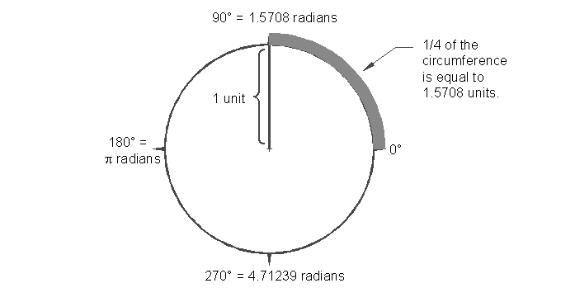
If the value returned by ang1 looks unfamiliar, it is because it is in radians. Radians are a way of describing an angle based on a circle whose radius is one unit. Such a circle will have a circumference of 2 pi. An angle of 90 degrees would describe a distance along the circle equivalent to 1/4 of the circles circumference or pi/2 or 1.5708 (see figure 4.4). This distance is the radian equivalent of the angle 90 degrees. We will discuss radians and their conversion to degrees in more detail in the next chapter.
77
Copyright © 2001 George Omura,,World rights reserved
The ABC’s of AutoLISP by George Omura
Figure 4.4: 90 degrees described in radians
Just as with getdist, if a point is selected using a cursor, you are prompted for a second point and a rubberbanding line appears. The rubberbanding line allows you to visually see the angle you are displaying in the drawing area. The second method is to enter an angle from the keyboard.
1. Enter the same expression you did previously:
(setq ang1 (getangle "Pick a point or enter angle: "))
2. Enter the following:
<45
The angle of 45 degrees is applied to the variable ang1 in radians.
3. Enter the following to find the value of Ang1:
!ang1
The value 0.785398 is returned. This is the radian equivalent of 45 degrees.
Just as with getdist, you can supply a point variable as an argument to getangle.
1. Enter the following expression:
(setq pt1 '(3 3))
This assigns the coordinate 3,3 to the variable pt1.
2. Enter the expression:
(setq ang1 (getangle pt1 "Indicate angle: "))
A rubber-banding line appears from the coordinate 3,3.
3.Pick a point at coordinate 7,6. The angle from pt1 to 7,6 is assigned to ang1.
4.To display the value of ang1, enter:
!ang1
The value 0.6463501 is returned. This is the radian equivalent to 37 degrees.
By accepting both keyboard and cursor input, these two functions offer flexibility to the user. Angles can be
78
Copyright © 2001 George Omura,,World rights reserved
The ABC’s of AutoLISP by George Omura
specified as exact numeric values or visually using the cursor. The Rotate command works in a similar way by accepting angular input as well as allowing the user to visually select an angle of rotation. Figure 4.5 summarizes the three ways you can use Getanglel
Figure 4.5: Three methods Getangle accepts for input
79
Copyright © 2001 George Omura,,World rights reserved