

- •Textbook Series
- •Contents
- •1 Definitions
- •Introduction
- •Abbreviations
- •Definitions
- •2 International Agreements and Organizations
- •The Chicago Convention
- •International Law
- •Commercial Considerations
- •Customs and Excise, and Immigration
- •International Obligations of Contracted States
- •Duties of ICAO Member States
- •Status of Annex Components
- •The International Civil Aviation Organization (ICAO)
- •The Organization of ICAO
- •Regional Structure of ICAO
- •Regional Structure and Offices
- •ICAO Publications
- •Other International Agreements
- •The Conventions of Tokyo, the Hague and Montreal
- •The Warsaw Convention
- •The Rome Convention
- •IATA
- •ECAC
- •EASA
- •Eurocontrol
- •World Trade Organization
- •Geneva Convention
- •EU Regulation 261/2004
- •Questions
- •Answers
- •3 Airworthiness of Aircraft
- •Introduction
- •Airworthiness
- •Questions
- •Answers
- •4 Aircraft Nationality and Registration Marks
- •Introduction
- •Nationality and Registration Marks
- •Certification of Registration
- •Aircraft Markings
- •Classification of Aircraft
- •Questions
- •Answers
- •5 Flight Crew Licensing
- •Introduction
- •Definitions
- •General Rules Concerning Licensing
- •Licences and Ratings for Pilots
- •Multi-crew Pilot Licence (MPL)
- •Instrument Rating (Aeroplane) (IR(A))
- •Instructor and Examiner Rating
- •JAR-FCL 3 Medical Requirements
- •Pilot Proficiency
- •EASA Theoretical Knowledge Examinations
- •Questions
- •Answers
- •6 Rules of the Air
- •History
- •Applicability of the Rules of the Air
- •General Rules
- •Visual Flight Rules
- •Instrument Flight Rules
- •Semi-circular Flight Level Rules and RVSM
- •Special VFR
- •Distress and Urgency Signals
- •Restricted, Prohibited or Danger Areas
- •Signals for Aerodrome Traffic
- •Marshalling Signals
- •Flight Deck Signals
- •Questions
- •Answers
- •Instrument Procedures
- •PANS OPS
- •Instrument Departure Procedures
- •Questions
- •Answers
- •8 Approach Procedures
- •Procedure Basics
- •Approach Procedure Design
- •Obstacle Clearance Altitude/Height
- •Operating Minima
- •Descent Gradients
- •Track Reversal and Racetracks
- •Missed Approach Segment and Procedure
- •Published Information
- •RNAV Approach Procedures based on VOR/DME
- •Questions
- •Answers
- •9 Circling Approach
- •Circling Approach
- •Questions
- •Answers
- •10 Holding Procedures
- •Holding Procedures
- •Entry Sectors
- •ATC Considerations
- •Obstacle Clearance
- •Questions
- •Answers
- •11 Altimeter Setting Procedure
- •Altimeter Setting Objectives
- •Transition
- •Phases of Flight
- •Questions
- •Answers
- •12 Parallel or Near-parallel Runway Operation
- •Safety
- •Runway Spacing
- •Questions
- •Answers
- •13 SSR and ACAS
- •Airborne Collision Avoidance System (ACAS)
- •Questions
- •Answers
- •14 Airspace
- •Introduction
- •Control Areas and Zones
- •Classes of Airspace
- •Required Navigation Performance (RNP)
- •Airways and ATS Routes
- •Questions
- •Answers
- •15 Air Traffic Services
- •Introduction
- •Air Traffic Control
- •ATC Clearances
- •Control of Persons and Vehicles at Aerodromes
- •The Flight Information Service
- •The Alerting Service
- •Procedures
- •Questions
- •Answers
- •16 Separation
- •Concept of Separation
- •Vertical Separation
- •Horizontal Separation
- •Radar Separation
- •Procedural Wake Turbulence Separation
- •Radar Wake Turbulence Separation
- •Visual Separation in the Vicinity of Aerodromes
- •Stacking
- •Questions
- •Answers
- •17 Control of Aircraft
- •Procedural ATC
- •Radar Control
- •Radar Identification
- •Radar Service
- •Aerodrome Control
- •Approach Control Service
- •Air Traffic Advisory Service
- •Aircraft Emergencies
- •Questions
- •Answers
- •18 Aeronautical Information Service (AIS)
- •Introduction
- •General
- •The Integrated Aeronautical Information Package
- •The Aeronautical Information Publication (AIP)
- •Notices to Airmen (NOTAM)
- •SNOWTAM
- •ASHTAM
- •Aeronautical Information Circulars (AICs)
- •Pre-flight and Post-flight Information
- •Questions
- •Answers
- •Introduction
- •Aerodrome Reference Code
- •Glossary of Terms
- •Aerodrome Data
- •Runways
- •Taxiways
- •Aprons
- •Questions
- •Answers
- •Requirements
- •Visual Aids for Navigation
- •Runway Markings
- •Taxiway Markings
- •Signs
- •Markers
- •Visual Docking Guidance Systems
- •Questions
- •Answers
- •21 Aerodrome Lighting
- •Aerodrome Lights
- •Approach Lighting Systems
- •Runway Lighting
- •Taxiway Lighting
- •Questions
- •Answers
- •22 Obstacle Marking and Aerodrome Services
- •Introduction
- •Visual Aids for Denoting Obstacles
- •Visual Aids for Denoting Restricted Use Areas
- •Emergency and Other Services
- •Other Aerodrome Services
- •Questions
- •Answers
- •23 Facilitation
- •Entry and Departure of Aircraft
- •Questions
- •Answers
- •24 Search and Rescue
- •Definitions and Abbreviations
- •Establishment and Provision of SAR Service
- •Co-operation between States
- •Operating Procedures
- •Questions
- •Answers
- •25 Security
- •Introduction
- •Objectives
- •Organization
- •Preventative Security Measures
- •Management of Response to Acts of Unlawful Interference
- •Further Security Information
- •Questions
- •Answers
- •26 Aircraft Accident and Incident Investigation
- •Introduction
- •Objective of Investigation
- •Investigations
- •Serious Incidents
- •EU Considerations
- •Questions
- •Answers
- •27 Revision Questions
- •Revision Questions
- •Answers
- •EASA Specimen Examination
- •Answers to Specimen EASA Examination
- •28 Addendum – EASA Part-FCL & Part-MED
- •Chapter Five. Flight Crew Licensing
- •European Aviation Safety Agency (EASA)
- •Licences
- •Ratings
- •Certificates
- •EASA Part-MED
- •29 Index
21 Aerodrome Lighting
Lighting Aerodrome 21
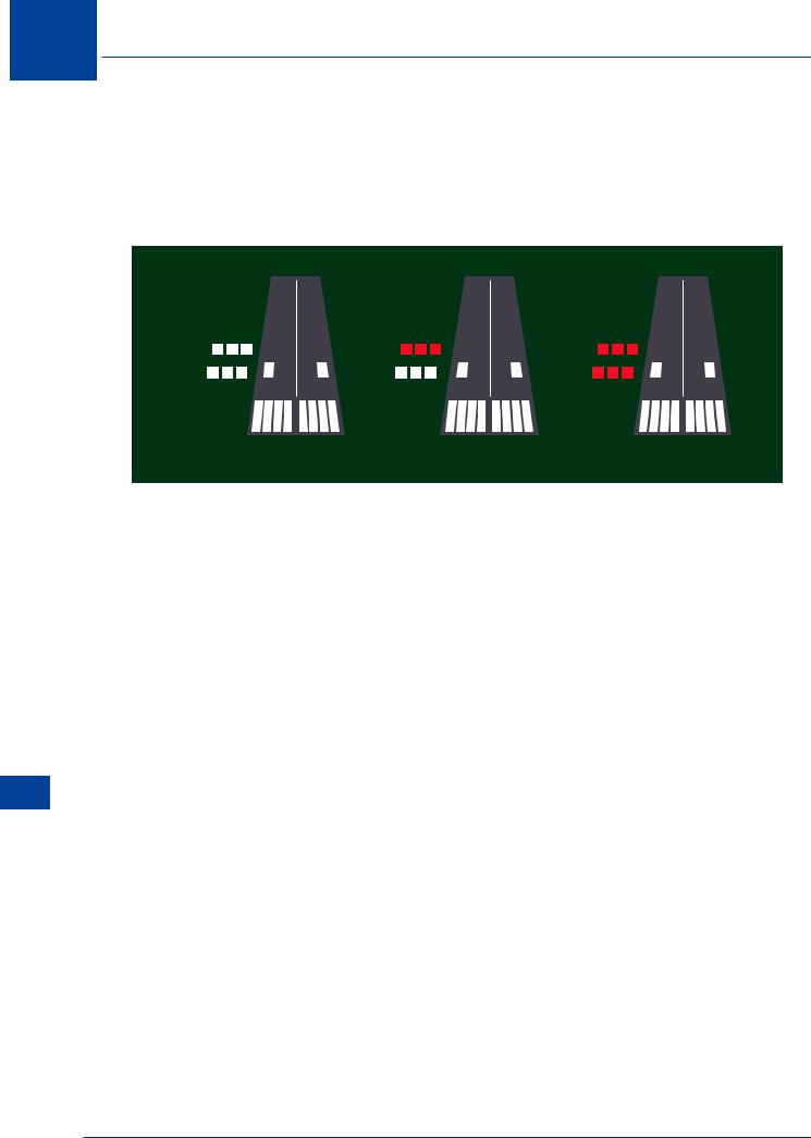
21.22 VASI. Standard Visual Approach Slope Indicator. This consists of 2 sets of 3 lights positioned as wing bars. Each set of lights is designed so that the lights appear as either white or red, depending on the angle at which the lights are viewed. When the pilot is approaching the lights on the glide slope the first set of lights appears white and the second set appears red. When both sets appear white, the pilot is flying too high, and when both appear red the approach is too low.
VASIs
TOO HIGH |
ON GLIDEPATH |
TOO LOW |
Figure 21.9 VASIs
Runway Lighting
21.23 Runway Edge Lights. Runway edge lights are provided for a runway intended for use at night or for a precision approach runway intended for use by day or night, and should be provided on a runway intended for take-off with an operating minimum below an RVR of the order of 800 m by day. Runway edge lights are placed along the full length of the runway in two parallel rows equidistant from the centre line. The lights shall be uniformly spaced. At intersections of runways, lights may be spaced irregularly or omitted, provided that adequate guidance remains available to the pilot. Runway edge lights are fixed, variable intensity white showing in the direction from which approaches are made. In the case of a displaced threshold, the lights between the beginning of the runway and the displaced threshold show red in the approach direction. A caution zone may be established over the last 600 m (or 1/3 of the runway whichever is least) where the lights are yellow. When the runway edge lights are intended to provide circling guidance, they shall show all round (omni-directional).
21.24Runway Threshold and Wing Bar Lights. Runway threshold lights are provided for a runway equipped with runway edge lights (except on a non-instrument or non-precision approach runway where the threshold is displaced and wing bar lights are provided). When the threshold is at the extremity of a runway, the threshold lights are placed in a row at right angles to the runway axis as near to the extremity of the runway as possible. For a displaced threshold, the lights are in the form of a barrette (wing bar) either side of the displaced threshold. Runway threshold and wing bar lights are to be fixed, unidirectional lights showing green in the direction of approach to the runway.
21.25Runway Threshold Identification Lights. Used at the threshold of a non-precision runway when additional threshold conspicuity is necessary or where the threshold is permanently displaced. They are flashing white lights unidirectional in the direction of the approach to the runway.
428

Aerodrome Lighting 21
21.26Runway End Lights. Runway end lights are provided for a runway equipped with runway edge lights. Runway end lights are fixed, unidirectional lights showing red in the direction of the runway. Runway end lights are placed in a line at right angles to the runway axis as near to the end of the runway as possible, and should consist of at least six lights. The lights should be either equally spaced between the rows of runway edge lights, or symmetrically disposed about the runway centre line.
21.27Runway Centre Line Lights. Runway centre line lights are provided on Cat II/III precision approach runways. They should be provided on a Cat I precision approach runway where the width between the runway edge lights is greater than 50 m. Runway centre line lights are to be provided on a runway intended to be used for take-off with an operating minimum below an RVR of the order of 400 m. Runway centre line lights are fixed, variable intensity white. Over the last 900 m from the runway end, the lights show alternate red and white from 900 m to 300 m from the runway end; and all red from 300 m to the runway end.
21.28Runway Touchdown Zone Lights. Touchdown zone lights are provided in the touchdown zone of a Cat II/III precision approach runway. Touchdown zone lights extend from the threshold for a distance of 900 m where the runway is 1800 m or more in length. The lights are arranged in the form of strips either side of the centre line, the width of the strips is to be the same width as the touchdown zone markings. Touchdown zone lights are fixed, variable intensity, unidirectional showing white.
21.29Stopway Lights. Stopway lights are provided for a stopway intended for use at night with the lights placed along the full length of the stopway. Stopway lights shall be fixed, variable intensity, unidirectional lights showing red in the direction of the runway.
21.30Runway Lead-in Lights. Runway lead-in lights provide visual guidance along a specific approach path to aircraft onto where the runway approach lighting is in view. The system may be curved, straight or a combination of both. They consist of groups of at least 3 flashing white lights and, where practical, each group should flash in sequence towards the runway.
21.31Circling Guidance Lights. Circling guidance lights are provided when existing approach and runway lighting do not permit identification of the runway to an aircraft undertaking a circling approach to land. They may be fixed or flashing white.
Taxiway Lighting
21.32Application. Taxiway lighting provides pilots with guidance and information during the taxi to and from the runway. It consists of centre line lights, edge lights, guard lights, and stop lights at holding points.
21.33Taxiway Edge Lighting. Taxiway edge lighting is provided along the edges of holding bays, de/anti-icing facilities, aprons etc. It is intended for use at night on taxiways not provided with taxiway centre line lighting. If, however, sufficient alternative illumination is available (e.g. stadium lighting) then the edge lights may be dispensed with. Where a runway forms part of a standard taxi route intended for use at night and no taxiway centre line lighting exists, edge lights are to be provided. Taxiway edge lights are fixed, variable intensity omni-directional blue.
Aerodrome Lighting 21
429
21 Aerodrome Lighting
Lighting Aerodrome 21
Figure 15.4 Taxiway Lighting
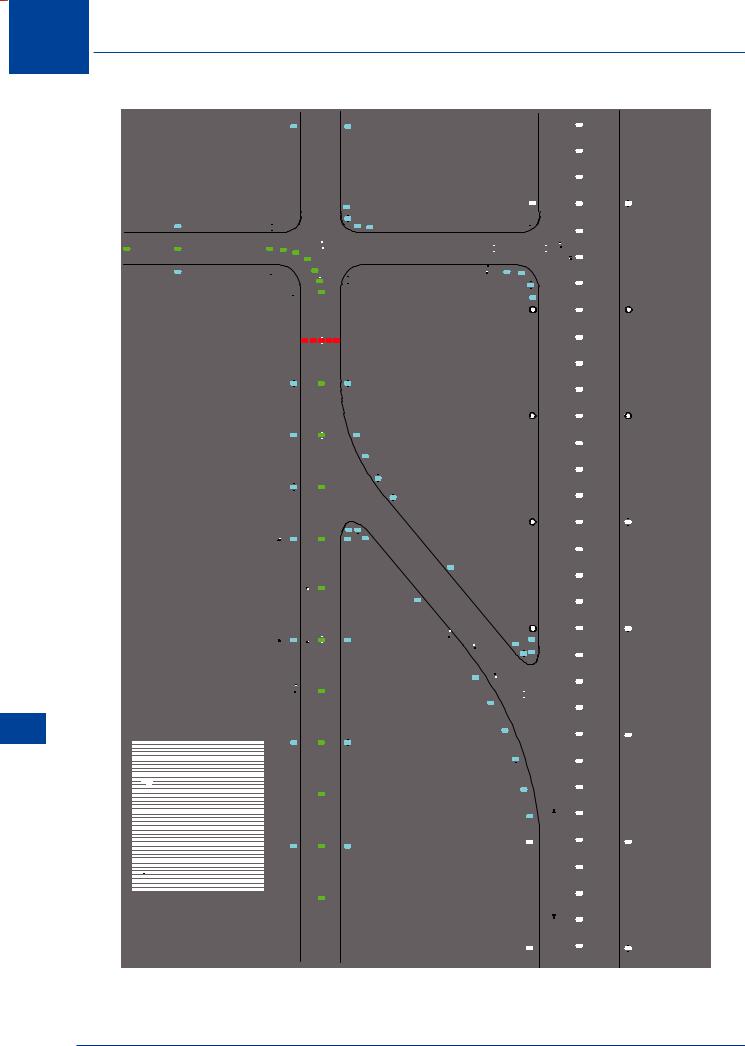
Figure 21.10 Arrangements of runway and taxiway lighting
430
|
|
|
|
|
|
|
|
|
|
|
|
|
|
|
|
Aerodrome Lighting |
|
21 |
|
|||||||||
21.34 Taxiway Centre Line Lights. Taxiway centre line lights are provided on an exit taxiway, |
||||||||||||||||||||||||||||
|
|
|
|
|||||||||||||||||||||||||
taxiway and apron intended for use in runway visual range conditions less than a value of 350 |
|
|
|
|
||||||||||||||||||||||||
m, in such a manner as to provide continuous guidance from the runway centre line to the |
|
|
|
|
||||||||||||||||||||||||
point on the apron where aircraft commence manoeuvring for parking. These lights need not |
|
|
|
|
||||||||||||||||||||||||
be provided where there is a low volume of traffic and taxiway edge lights and centre line |
|
|
|
|
||||||||||||||||||||||||
marking provide adequate guidance. Taxiway centre line lights shall be provided on a runway |
|
|
|
|
||||||||||||||||||||||||
forming part of a standard taxiway route and intended for taxiing in runway visual range |
|
|
|
|
||||||||||||||||||||||||
conditions less than a value of 350 m. Taxiway centre line lights are fixed, variable intensity |
|
|
|
|
||||||||||||||||||||||||
showing green such that the light is visible only from the aeroplanes on or in the vicinity of the |
|
|
|
|
||||||||||||||||||||||||
taxiway. Within the ILS/MLS critical/sensitive area, the centre line lights are alternating green |
|
|
|
|
||||||||||||||||||||||||
and yellow. This is the same for a high-speed exit. Where aircraft may follow the same centre |
|
|
|
|
||||||||||||||||||||||||
line in both directions, all the centre line lights shall show green to aircraft approaching the |
|
|
|
|
||||||||||||||||||||||||
runway. |
|
|
|
|
|
|
|
|
|
|
|
|
|
|
|
|
|
|
|
|
|
|
|
|
||||
21.35 Stop Bars. Stop bars are a row of red lights showing in the direction of taxiing aircraft |
|
|
|
|
||||||||||||||||||||||||
and when illuminated require the aircraft to stop and not proceed until cleared by ATC. One |
|
|
|
|
||||||||||||||||||||||||
or more stop bars, as appropriate, should be provided at a taxiway intersection or taxi-holding |
|
|
|
|
||||||||||||||||||||||||
position when it is desired to supplement markings with lights and to provide traffic control by |
|
|
|
|
||||||||||||||||||||||||
visual means. A stop bar shall be provided at every taxi-holding position serving a runway when |
|
|
|
|
||||||||||||||||||||||||
it is intended that the runway will be used in runway visual range conditions less than a value of |
|
|
|
|
||||||||||||||||||||||||
350 m. Where the normal stop bar lights might be obscured (from a pilot’s view), for example, |
|
|
|
|
||||||||||||||||||||||||
by snow or rain, or where a pilot may be required to stop the aircraft in a position close to the |
|
|
|
|
||||||||||||||||||||||||
lights that they are blocked from view by the structure of the aircraft, a pair of elevated lights |
|
|
|
|
||||||||||||||||||||||||
should be added to each end of the stop bar. |
|
|
|
|
|
|
|
|
|
|
|
|
|
|
||||||||||||||
21.36 Intermediate Holding Position Lights. Intermediate Holding Position lights consist of |
|
|
|
|
||||||||||||||||||||||||
3 fixed unidirectional lights showing yellow in the direction of approach and at right angles to |
|
|
|
|
||||||||||||||||||||||||
the taxiway. |
|
|
|
|
|
|
|
|
|
|
|
|
|
|
|
|
|
|
|
|
|
|
|
|
||||
21.37 Road-holding Position Lights. Comprise of either : |
|
|
|
|
||||||||||||||||||||||||
|
a. |
|
a controllable red (stop) / green (go) or |
|
|
|
|
|
|
|
|
|
|
|
|
|
|
|||||||||||
|
b. |
|
a flashing red light |
|
|
|
|
|
|
|
|
|
|
|
|
|
|
|||||||||||
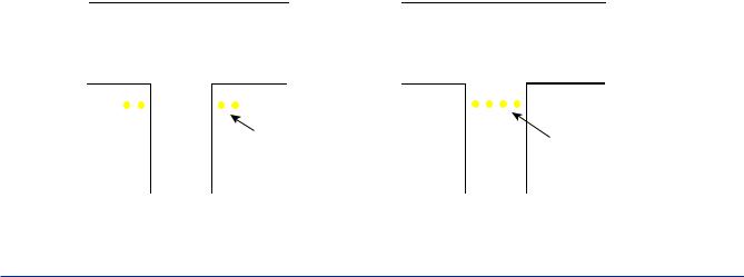
21.38 Runway Guard Lights. These are used to warn pilots and drivers of vehicles that they |
|
|
|
|
||||||||||||||||||||||||
are about to enter an active runway. They are installed at the entrance to runways used in RVR |
|
|
|
|
||||||||||||||||||||||||
conditions less than 550 m where a stop bar is not fitted, and in RVR conditions of 550 - 1200 |
|
|
21 |
|
||||||||||||||||||||||||
m where traffic density is high. There are two configurations of runway guard lights known as |
|
|
||||||||||||||||||||||||||
|
|
|
|
|||||||||||||||||||||||||
|
|
Lighting |
||||||||||||||||||||||||||
of taxiing aircraft. |
|
|
|
|
|
|
|
|
|
|
|
|
||||||||||||||||
Configuration A and Configuration B. The lights are flashing yellow and show in the direction |
|
|
|
|
||||||||||||||||||||||||
|
|
|
|
|
|
|
|
|
|
|
|
|
|
|
|
|
|
|
|
|
|
|
|
|
|
Aerodrome |
||
|
|
|
|
|
|
|
|
|
|
|
|
|
|
|
|
|
|
|
|
|
|
|
|
|
|
|||
|
|
|
|
|
|
|
|
|
|
|
A pair of |
|
|
|
|
|
|
Unidirectional |
|
|
|
|
|
|||||
|
|
|
|
|
|
|
|
|
|
|
unidirectional, |
|
|
|
|
|
|
ashing yellow |
|
|
|
|
|
|||||
|
|
|
|
|
|
|
|
|
|
|
ashing |
|
|
|
|
|
|
lights spaced at |
|
|
|
|
|
|||||
|
|
|
|
|
|
|
|
|
|
|
yellow lights. |
|
|
|
|
|
|
intervals of 3 m. |
|
|
|
|
|
|||||
|
|
|
|
Con guration A |
Con guration B |
|
|
|
|
|
||||||||||||||||||
|
|
|
|
|
|
|
|
|
|
|
|
|
|
|
|
|
|
|
|
|
|
|
|
|
|
|
|
|
Figure 21.11 Runway and guard lights
431