


Chapter
10
Holding Procedures
Holding Procedures |
|
|
|
|
|
209 |
Entry Sectors . . . . . . . . . . . . |
. . |
. . |
. . . . . . . . . . |
. . |
. . |
211 |
ATC Considerations . . . . . . . . . . |
. . |
. . |
. . . . . . . . . . |
. . |
. . |
213 |
Obstacle Clearance . . . . . . . . . . |
. . |
. . |
. . . . . . . . . . |
. . |
. . |
214 |
Questions . . . . . . . . . . . . . . |
. . |
. . |
. . . . . . . . . . |
. . |
. |
216 |
Answers . . . . . . . . . . . . . . |
. . |
. . |
. . . . . . . . . . |
. . |
. . |
218 |
207

10 Holding Procedures
Procedures Holding 10
208
Holding Procedures
Holding Procedures
10.1Introduction. Holding is the equivalent to temporary parking areas for aeroplanes. Clearly (unless you are flying a rotorcraft) you cannot stop, but you can remain (hold) in the vicinity of a radio navigation facility for as long as is required (fuel permitting!). Providing you can fly the aeroplane accurately and navigate with reference to a radio navigation aid (VOR, NDB) or a fix position, holding is a feasible option for losing time. Indeed, in bad weather or at times of peak traffic flow, you will be lucky to get a ‘straight-in’ approach. All instrument arrivals start from a holding pattern established at the IAF. In a holding pattern, aircraft are ‘stacked’ up, one on top of another with the necessary vertical separation applied (1000 ft). As the bottom aircraft departs the holding pattern to fly the approach procedure, the others above are ‘shuttled’ (descended in the stack) to a lower level one at a time.
10.2Deviation Warning. It must be noted that deviations from the in-flight procedures for holding incur the risk of excursions beyond the perimeters of holding areas established in accordance with the provisions of PANS OPS. The procedures described in PANS OPS relate to right turn holding patterns. For left turn holding patterns, the corresponding entry and holding procedures are symmetrical with respect to the inbound holding track.
10.3Shape and Terminology. The shape of holding patterns and the associated terminology are shown below. A standard holding pattern has starboard (right) turns. If port turns are required, the approach plate will be annotated to indicate the fact. A left hand pattern is a mirror image of the standard pattern.
All turns at rate 1 |
Abeam |
Holding Side |
|
or 25° bank angle |
d |
||
whichever requires |
|
|
|
the lesser bank |
Outbound |
|
|
|
|
||
Fix End |
|
Outbound End |
|
|
|
Inbound |
|
Fix or facility |
Non-holding Side |
||
‘d’ = 1 min in still air at 14 000 |
|||
|
|||
and below; and 1½ min above 14 000 |
|
||
Figure 10.1 Holding pattern terminology
10
Holding Procedures 10
209

10 Holding Procedures
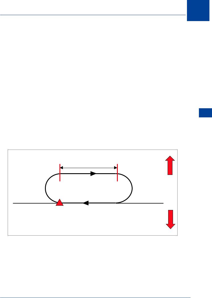
10.4 Flying the Pattern. In flying the holding pattern described, all turns are to be made at an angle of bank of 25° or at a rate of 3° per second (rate 1), whichever requires the lesser bank. All the procedures depict tracks and pilots should attempt to maintain the track by making allowance for known wind by applying corrections both to heading and timing during entry and while flying the holding pattern. Outbound timings begin over or abeam the fix whichever occurs later. If the abeam position cannot be determined, start the timing when the turn to outbound is completed. The outbound track should be flown for 1 minute at 14 000 ft and below and 1½ minutes above 14 000 ft. If the outbound leg is based on a DME distance, the outbound leg terminates as soon as the limiting DME distance is attained. If, for any reason, a pilot is unable to conform to procedures for normal conditions, ATC should be informed as soon as possible. Holding patterns are to be flown at speeds given in the table below.
|
|
|
Levels 1 |
Normal Conditions |
Turbulence Conditions |
|
|
|
|
|
|
||
|
|
up to 4250 m (14 000 ft) |
425 km/h (230 kt)2 |
520 km/h (280 kt)3 |
||
10 |
||||||
|
|
inclusive |
315 km/h (170 kt)4 |
315 km/h (170 kt)4 |
||
|
|
|
||||
Holding |
|
|
|
|
|
|
|
above 4250 m (14 000 ft) to |
445 km/h (240 kt)5 |
520 km/h (280 kt) |
|||
|
|
|
|
|||
Procedures |
|
6100 m (20 000 ft) inclusive |
490 km/h (265 kt)5 |
Mach 0.8, whichever is less 3 |
||
|
|
|
|
|
or |
|
|
|
above 6100 m (20 000 ft) to |
|
|||
|
|
|
|
|||
|
|
10 350 m (34 000 ft) inclusive |
|
|
||
|
|
|
|
|
||
|
|
above 10 350 m |
Mach 0.83 |
Mach 0.83 |
||
|
|
|
(34 000ft) |
|||
|
|
|
|
|
||
|
|
|
|
|
|
|
|
|
Notes: |
|
|
|
|
|
|
1 |
The levels tabulated represent altitudes or corresponding flight levels |
|||
|
|
|
depending upon the altimeter setting in use. |
|
||
|
|
2 |
When the holding procedure is followed by the initial segment of an instrument |
|||
|
|
|
approach procedure promulgated at a speed higher than 425 km/h (230 kt), |
|||
|
|
|
the holding should also be promulgated at this higher speed wherever possible |
|||
|
|
3 |
The speed of 520 km/h (280 kt) (Mach 0.8) reserved for turbulence conditions |
|||
|
|
|
shall be used for holding only after prior clearance with ATC, unless the relevant |
|||
|
|
|
publications indicate that the holding area can accommodate aircraft at these |
|||
|
|
|
flight holding speeds |
|
||
|
|
4 |
For holdings limited to CAT A and B aircraft only. |
|||
|
|
5 |
Wherever possible, 520 km/h (280 kt) should be used for holding procedures |
|||
|
|
|
associated with airway route structures. |
|
||
|
|
|
|
|
|
|
|
|
|
|
Figure 10.2 Holding speeds |
|
|
210