

8 |
|
Approach Procedures |
|
||
|
|
|
Procedures Approach 8
8.12 Limitations. An instrument approach shall not be continued beyond the outer marker fix, or if no OM is provided the equivalent position, in case of precision approach, or below 300 m (1000 ft) above the aerodrome in case of non-precision approach, unless the reported visibility or controlling RVR is above the specified minimum. If, after passing the outer marker fix, or equivalent position, in case of precision approach, or after descending below 300 m (1000 ft) above the aerodrome in case of non-precision approach, the reported visibility or controlling RVR falls below the specified minimum, the approach may be continued to DA/H or MDA/H. If the required visual criteria are then obtained at DH, the aircraft may be landed.
Approach Procedure Design
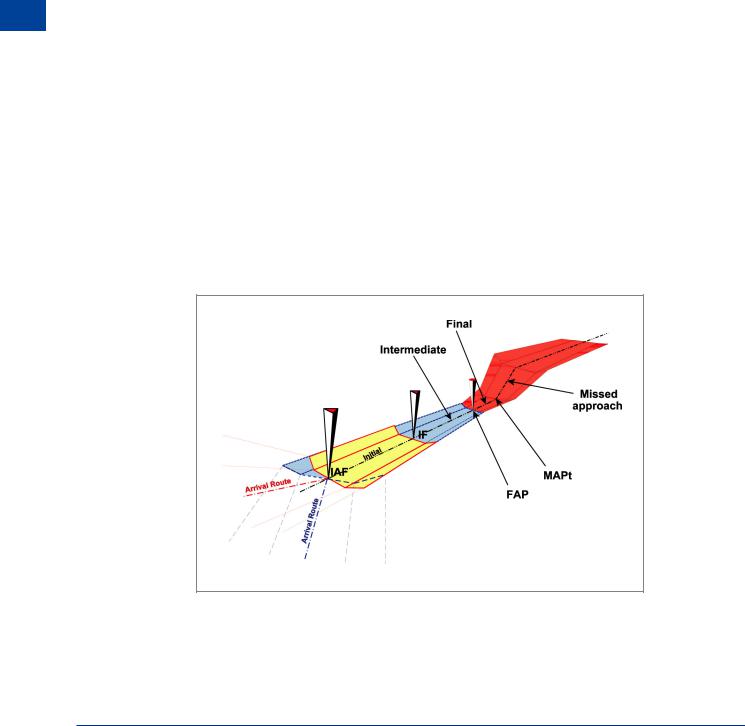
8.13 Procedure Requirements. An instrument approach procedure requires the aeroplane to be flown in safe airspace. In order to remain in safe airspace the required track of the aeroplane must be achievable and the altitude limitations which need to be applied must be commensurate with what is trying to be achieved. As the procedure takes the aeroplane closer to the runway/aerodrome and closer to the ground, the safety limitations must be increased not relaxed. Until 3-D satellite navigation technology is widely available and proved reliable, the system of guidance in azimuth and elevation will rely on ground based equipment which has inherent errors. Providing the error tolerances are known and the design of the procedure detailing the flight path to be flown takes the error tolerances into account, the procedure will be usable. It does of course require the pilot (or the auto-pilot) to be able to fly the aeroplane to the required basic accuracy to keep the aeroplane in the airspace specified. The procedure will define tracks to be made good, therefore the pilot must make allowance for the wind. An instrument approach procedure has five separate segments, each of which has a specific purpose. Each of the five segments begins and ends at a designated fix. It is, however, possible for segments to begin at specified points if no fix is available. For instance, the final approach segment of a precision approach may begin at the point of intersection of the intermediate flight altitude and the glide path.
Figure 8.3 Procedure segments
170

|
Approach Procedures |
|
8 |
|
||
8.14 Procedure Segments. An approach procedure consists of five parts or segments. |
||||||
|
|
|
|
|||
These are: |
|
|
|
|
||
• The Arrival Segment or Route (see 8.20 below) |
|
|
|
|
||
• The Initial Segment (see 8.21 below) |
|
|
|
|
||
• |
The Intermediate Segment (see 8.22 below) |
|
|
|
|
|
• |
The Final Segment (see 8.23 below) |
|
|
|
|
|
• |
The Missed Approach Segment and Procedure (see 8.47 below) |
|
|
|
|
|
8.15 Straight-in Approach. Wherever possible a straight-in approach will be specified in |
|
|
|
|
||
which each segment is aligned with the extended runway centre line. However, a non-precision |
|
|
|
|
||
approach may specify the final approach track converging to the runway heading at an angle |
|
|
|
|
||
of 30° or less. In all cases, the procedures depict still air tracks and pilots are required to |
|
|
|
|
||
|
|
|
|
|||
make allowance for the wind to make good the specified track. If terrain or other restrictions |
|
|
8 |
|
||
preclude a straight-in approach, a circling approach will be specified. In addition, an aircraft |
|
|
|
|
||
|
|
Procedures |
||||
may be offered an omni-directional or sector arrival by ATC when appropriate and taking into |
|
|
||||
|
|
|
|
|||
consideration the MSA (Minimum Safety Altitude). The definition of being established on an |
|
|
|
|
||
NDB is to be within 5° either side of the final approach track. |
|
|
Approach |
|||
|
|
|
|
|||
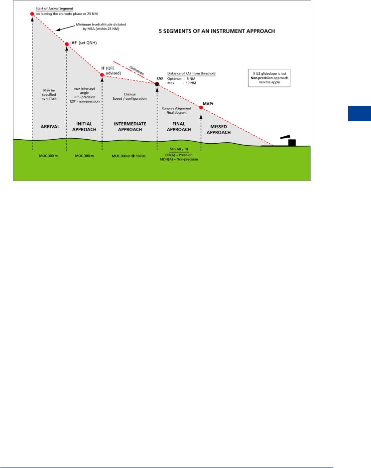
8.16 Physical Characteristics of Segments. The vertical cross section of each segment is divided into primary and secondary MOC areas. Full obstacle clearance is applied over the primary area, reducing to zero at the outer edges of the secondary areas.
Figure 8.4 Characteristics of segments
171

8 |
|
Approach Procedures |
|
||
|
|
|
Procedures Approach 8
8.17 Fixes and Fix Accuracy. The fixes used in instrument procedures are generally based on data from radio navigation aids e.g. VOR. The fix may be an ‘on top’ to a beacon or a point defined by a DME range on a specified radial (way point). In any event, the accuracy of the fix is of paramount importance because the width of the MOC area will be based upon this. For ‘on top’ fixes the type of aid is a limiting factor. For instance, a VOR is designed to give accurate track guidance but is quite poor in giving an ‘on top’ indication due to the size of the ‘cone of confusion’ over the beacon. An NDB, on the other hand, gives a better ‘on top’ but the track guidance is worse! Where an accurate ‘on top’ is required, e.g. the outer marker of a CAT 1 ILS, a 75 MHz (or ‘Z’ or ‘fan’ marker) is used which is designed specifically for that purpose. Where a fix is specified using information from two separate systems e.g. VOR radial and DME range, the inaccuracies of each system must be aggregated to define a fix tolerance area. In determining the accuracy of fixes the following bearing error is assumed:
• |
VOR |
± 4.5° |
• |
ILS Localizer |
± 1.4° |
• |
NDB |
± 10.3° |
|
|
|
|
|
|
Figure 8.5
8.18 Track Guidance Accuracy. The width of the MOC area is also dependent upon the accuracy of the track guidance provided by the navigation aids used. The track accuracy for the various aids is defined as follows:
• |
VOR |
± 5.2° |
• |
ILS Localizer |
± 2.4° |
• |
NDB |
± 6.9° |
8.19Fix Tolerances for other navigation aids.
•Terminal Area Surveillance Radar (TAR) : Within 20 NM = ±1.5 km (0.8 NM)
•En route Surveillance Radar (RSR) : Within 40 NM = ±3.1 kms (1.7 NM)
•DME : ±0.46 km (0.25 NM) + 1.25 per cent of the distance to the antenna
172
Approach Procedures |
|
8 |
|
||
|
|
|
Approach Procedures 8
Figure 8.6
8.20 Arrival Route/Segment. The arrival segment begins at the point the aircraft departs from the en route airways system to begin the instrument arrival. This will normally be a radio navigation facility. If this is 25 NM or more from the aerodrome, a standard arrival route (STAR) will be specified. The STAR plate below shows the arrival routes for London Heathrow from the northwest (via the Ockham (OCK) VOR). If the distance is less than 25 NM then the aircraft will route directly from the point of leaving the airway to the facility serving as the IAF for the procedure. In either case, the en route MOC is applied and the altitude specified for the aircraft to be over the IAF is not below the highest MSA for the aerodrome. It is usual for aircraft to be radar vectored from a convenient point, to the final approach track.
173

8 |
|
Approach Procedures |
|
||
|
|
|
Procedures Approach 8
Figure 8.7
174
Approach Procedures |
|
8 |
|
||
|
|
|
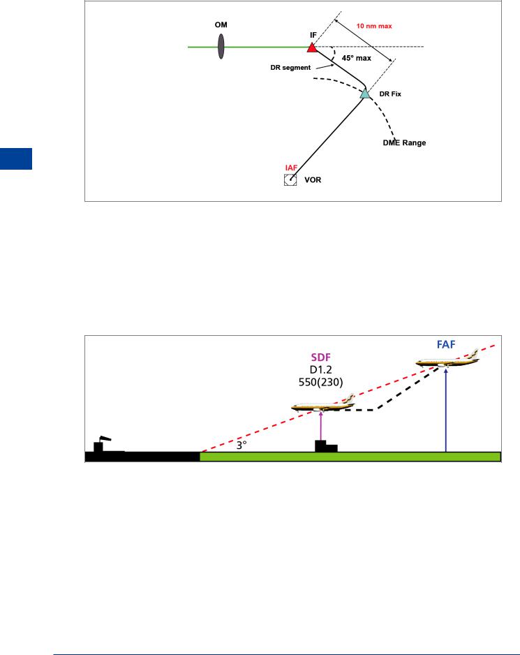
8.21 Initial Segment. In the initial segment, the aircraft is directed to a point at which the intermediate segment can be intercepted. It starts at the IAF and ends at the IF. Aircraft speed and configuration will depend upon distance from the aerodrome and any need for descent. MOC in the initial segment is 300 m (984 ft). Track guidance is normally provided with a maximum intercept angle to the IF of 90° for a precision approach and 120° for a non-precision approach. If track guidance to the IF is not available, a DR segment may be specified. For the DR segment, the interception angle to the intermediate segment track must be no greater then 45°, and the length of the DR track, no more than 10 NM. Where a straight-in approach is not feasible or there is no suitable remote IAF or IF, a track reversal, racetrack or holding pattern is required.
Approach Procedures 8
Figure 8.8 IAF to IF (precision approach)
Figure 8.9 IAF to IF (non-precision approach)
8.22Intermediate Segment. This is the segment in which the aircraft speed and configuration is adjusted to prepare for the final approach. Descent in this segment is kept to a minimum. It starts at the IF and ends at the FAF. If no FAF exists, it ends when the aircraft is established on the final inbound track. The MOC in the intermediate segment reduces from 300 m at the IF to 150 m at the end of the segment.
8.23Final Segment. The beginning of the final segment depends upon the type of approach and the availability of a suitable FAF. In this segment, the aircraft is finally configured, alignment with the runway takes place and descent for landing is commenced.
175
8 |
|
Approach Procedures |
|
||
|
|
|
Procedures Approach 8
Figure 8.10 IAF to IF (DR segment)
8.24 Non-precision with FAF. For a non-precision procedure with a FAF, the final segment starts at the FAF and ends at the MAPt. The FAF will be positioned on the final approach track at a distance from the threshold of the landing runway that permits aircraft configuration for final approach/landing and descent from the intermediate altitude to the MDA/H. MOC is incorporated in the calculation of MDA/H. The optimum distance of the FAF from the threshold is 5 NM and the maximum is 10 NM. The required descent gradient should be 300 ft/NM (approx 3°). A step-down fix may be incorporated for obstacle clearance purposes in which case, two OCA/H values will be published.
Figure 8.11 Step-down fix
8.25Non-precision without FAF. This situation will normally occur at an aerodrome where there is only one facility on or near the aerodrome that is used as both the IAF and the MAPt. In this case it is unlikely that the final approach track will be aligned with the runway centre line and therefore descent to MDA/H will be made when the aircraft is established inbound on the final approach track.
8.26Precision Approach. For ILS/MLS the final segment begins at the Final Approach Point (FAP). This is defined as the point in space on localizer centre line (or the specified MLS azimuth) where the intermediate approach altitude intercepts the nominal glide path. This can occur at heights between 300 m (1000 ft) and 900 m (3000 ft) which in the case of a 3° (300 ft/NM) glide path, will be between 3 NM and 10 NM from touchdown. MOC is included in the calculation for DA/H but requires the pilot to fly the aircraft with no more than half scale
176