

- •Textbook Series
- •Contents
- •1 Definitions
- •Introduction
- •Abbreviations
- •Definitions
- •2 International Agreements and Organizations
- •The Chicago Convention
- •International Law
- •Commercial Considerations
- •Customs and Excise, and Immigration
- •International Obligations of Contracted States
- •Duties of ICAO Member States
- •Status of Annex Components
- •The International Civil Aviation Organization (ICAO)
- •The Organization of ICAO
- •Regional Structure of ICAO
- •Regional Structure and Offices
- •ICAO Publications
- •Other International Agreements
- •The Conventions of Tokyo, the Hague and Montreal
- •The Warsaw Convention
- •The Rome Convention
- •IATA
- •ECAC
- •EASA
- •Eurocontrol
- •World Trade Organization
- •Geneva Convention
- •EU Regulation 261/2004
- •Questions
- •Answers
- •3 Airworthiness of Aircraft
- •Introduction
- •Airworthiness
- •Questions
- •Answers
- •4 Aircraft Nationality and Registration Marks
- •Introduction
- •Nationality and Registration Marks
- •Certification of Registration
- •Aircraft Markings
- •Classification of Aircraft
- •Questions
- •Answers
- •5 Flight Crew Licensing
- •Introduction
- •Definitions
- •General Rules Concerning Licensing
- •Licences and Ratings for Pilots
- •Multi-crew Pilot Licence (MPL)
- •Instrument Rating (Aeroplane) (IR(A))
- •Instructor and Examiner Rating
- •JAR-FCL 3 Medical Requirements
- •Pilot Proficiency
- •EASA Theoretical Knowledge Examinations
- •Questions
- •Answers
- •6 Rules of the Air
- •History
- •Applicability of the Rules of the Air
- •General Rules
- •Visual Flight Rules
- •Instrument Flight Rules
- •Semi-circular Flight Level Rules and RVSM
- •Special VFR
- •Distress and Urgency Signals
- •Restricted, Prohibited or Danger Areas
- •Signals for Aerodrome Traffic
- •Marshalling Signals
- •Flight Deck Signals
- •Questions
- •Answers
- •Instrument Procedures
- •PANS OPS
- •Instrument Departure Procedures
- •Questions
- •Answers
- •8 Approach Procedures
- •Procedure Basics
- •Approach Procedure Design
- •Obstacle Clearance Altitude/Height
- •Operating Minima
- •Descent Gradients
- •Track Reversal and Racetracks
- •Missed Approach Segment and Procedure
- •Published Information
- •RNAV Approach Procedures based on VOR/DME
- •Questions
- •Answers
- •9 Circling Approach
- •Circling Approach
- •Questions
- •Answers
- •10 Holding Procedures
- •Holding Procedures
- •Entry Sectors
- •ATC Considerations
- •Obstacle Clearance
- •Questions
- •Answers
- •11 Altimeter Setting Procedure
- •Altimeter Setting Objectives
- •Transition
- •Phases of Flight
- •Questions
- •Answers
- •12 Parallel or Near-parallel Runway Operation
- •Safety
- •Runway Spacing
- •Questions
- •Answers
- •13 SSR and ACAS
- •Airborne Collision Avoidance System (ACAS)
- •Questions
- •Answers
- •14 Airspace
- •Introduction
- •Control Areas and Zones
- •Classes of Airspace
- •Required Navigation Performance (RNP)
- •Airways and ATS Routes
- •Questions
- •Answers
- •15 Air Traffic Services
- •Introduction
- •Air Traffic Control
- •ATC Clearances
- •Control of Persons and Vehicles at Aerodromes
- •The Flight Information Service
- •The Alerting Service
- •Procedures
- •Questions
- •Answers
- •16 Separation
- •Concept of Separation
- •Vertical Separation
- •Horizontal Separation
- •Radar Separation
- •Procedural Wake Turbulence Separation
- •Radar Wake Turbulence Separation
- •Visual Separation in the Vicinity of Aerodromes
- •Stacking
- •Questions
- •Answers
- •17 Control of Aircraft
- •Procedural ATC
- •Radar Control
- •Radar Identification
- •Radar Service
- •Aerodrome Control
- •Approach Control Service
- •Air Traffic Advisory Service
- •Aircraft Emergencies
- •Questions
- •Answers
- •18 Aeronautical Information Service (AIS)
- •Introduction
- •General
- •The Integrated Aeronautical Information Package
- •The Aeronautical Information Publication (AIP)
- •Notices to Airmen (NOTAM)
- •SNOWTAM
- •ASHTAM
- •Aeronautical Information Circulars (AICs)
- •Pre-flight and Post-flight Information
- •Questions
- •Answers
- •Introduction
- •Aerodrome Reference Code
- •Glossary of Terms
- •Aerodrome Data
- •Runways
- •Taxiways
- •Aprons
- •Questions
- •Answers
- •Requirements
- •Visual Aids for Navigation
- •Runway Markings
- •Taxiway Markings
- •Signs
- •Markers
- •Visual Docking Guidance Systems
- •Questions
- •Answers
- •21 Aerodrome Lighting
- •Aerodrome Lights
- •Approach Lighting Systems
- •Runway Lighting
- •Taxiway Lighting
- •Questions
- •Answers
- •22 Obstacle Marking and Aerodrome Services
- •Introduction
- •Visual Aids for Denoting Obstacles
- •Visual Aids for Denoting Restricted Use Areas
- •Emergency and Other Services
- •Other Aerodrome Services
- •Questions
- •Answers
- •23 Facilitation
- •Entry and Departure of Aircraft
- •Questions
- •Answers
- •24 Search and Rescue
- •Definitions and Abbreviations
- •Establishment and Provision of SAR Service
- •Co-operation between States
- •Operating Procedures
- •Questions
- •Answers
- •25 Security
- •Introduction
- •Objectives
- •Organization
- •Preventative Security Measures
- •Management of Response to Acts of Unlawful Interference
- •Further Security Information
- •Questions
- •Answers
- •26 Aircraft Accident and Incident Investigation
- •Introduction
- •Objective of Investigation
- •Investigations
- •Serious Incidents
- •EU Considerations
- •Questions
- •Answers
- •27 Revision Questions
- •Revision Questions
- •Answers
- •EASA Specimen Examination
- •Answers to Specimen EASA Examination
- •28 Addendum – EASA Part-FCL & Part-MED
- •Chapter Five. Flight Crew Licensing
- •European Aviation Safety Agency (EASA)
- •Licences
- •Ratings
- •Certificates
- •EASA Part-MED
- •29 Index

Control of Aircraft 17
17.7 Radar Separation. There is only one radar separation standard and this is 5 NM. As defined in Chapter 16, reduced radar separation may be applied under specific conditions. The separation applied is based upon the aircraft position derived from PSR only. As defined and specified in Chapter 16, wake turbulence separation can be applied using radar derived information. In this case the separation standards applied are based on distance.
Radar Identification
17.8 Requirement. Before a radar controller can provide any service to an aircraft, the radar identity of the aircraft must be established. Clearly, the basic SSR capability is to identify a specific aircraft squawking a specifically allocated code, therefore this method of identification is most commonly used. It is also the quickest method of identification. Once an aircraft has been allocated an SSR code, it must be retained until otherwise advised by the radar controller. If an emergency situation arises, the pilot should not squawk A7700 if the identity of the aircraft has already been established using SSR. All other methods of identification by radar require the ATCO to observe the radar contacts on the display screen and determine, either from geographic position or from a specific manoeuvre, which contact is the aircraft requiring the service. Such observations include:
•Geographic location e.g. ‘2 NM west of Woodstock’
•Relative to a radio navigation aid - “On the 230 radial from the Daventry VOR DME 5 NM”
•Latitude and longitude
•Georef position
•Turn through 30° or more away from desired course and then return to the course
•Positive handover from a radar controller who had previously identified the aircraft
17.9 Procedure. When identifying a radar contact as a specific aircraft, the radar controller must tell the pilot how the identification was achieved. The controller will use the phrase ‘radar contact’ to indicate that the aircraft has been identified and that until further advised, a service will be provided - “G-CD radar contact 2 NM west of Oxford”. This position should agree with the position the pilot thinks the aircraft is at. If significantly different, the pilot must inform the controller in the event that the controller has misidentified the aircraft.
Radar Service
17.10Commencement. After identification, the pilot is to be told what type of radar service is to be provided and what the objective is - “G-CD radar contact 6 NM west of Compton, radar control, expect radar vectors for ILS approach runway 26”
17.11Termination. When an aircraft reaches the limit of radar cover or the edge of a radar vectoring area, or the aim of the service has been achieved, the pilot will be advised that the service is terminated, given position information and instructions/advice how to continue. For instance: “G-CD radar service terminated, presently 10 NM south of Benson, resume own navigation, suggest continue with London Information 125.650”
Control of Aircraft 17
327

17 Control of Aircraft
Aircraft of Control 17
17.12 Radar Vectoring. Radar vectoring is the passing of navigation information to a pilot by a radar controller to achieve the aircraft flying a required track. This may be simply to avoid weather or manoeuvre around another aircraft radar contact. Once the aim of the vectoring has been achieved, the pilot will be told to “Resume own navigation” giving the pilot the aircraft’s position and any appropriate instructions. This implies that the radar vectoring has ended. It may be provided to position the aircraft such that a straight-in instrument approach can be achieved. In any event, radar vectoring for approach control purposes is only carried out inside a radar vectoring area (RVA). Obstacles are marked on an RVA chart.
MSA outside of RVA
Radar Vectoring
Area Boundary
Safety altitude inside of RVA
Figure 17.3 Radar vectoring area
17.13 Vectoring Procedure. Radar vectoring will not begin until the aircraft radar contact is determined to be within the RVA. The RVA will be displayed on the radar display in the form of a video map electronically generated within the radar display software. Because of possible inaccuracies (‘slippage’) aircraft will not be radar vectored closer to the edge of the RVA than half the applicable radar separation standard or 2.5 NM whichever is greater. Normally, radar vectoring will begin at a fix at MSA. It may, however, begin at any time after the aircraft has been identified on radar and the aircraft altitude is known to the ATCO. The RVA chart displays the obstacles in the area together with the elevation of the terrain. The radar controller will pass magnetic headings to the pilot to steer to make good a desired track over the ground. The pilot will fly the heading and the controller will adjust the heading for the wind. The aircraft will not be given clearance to descend below the RVA safe altitude (highest obstacle in RVA plus MOC rounded up) until established on the ILS localizer course or on the final approach track, or the pilot reports that he/she is continuing the approach visually. Throughout the procedure, the radar controller must be aware of the elevation of the terrain and the aircraft configuration to avoid spurious GPWS warnings.
328

Control of Aircraft |
|
17 |
|
||
17.14 ILS Vectoring Requirements. Where the purpose of vectoring is to position the aircraft |
|||||
|
|
|
|
||
at a point where localizer capture is achieved, the closing heading to the centre line of the ILS |
|
|
|
|
|
localizer is 45°. If parallel runway operations Modes 1 or 2 are in use, the angle is limited to 30°. |
|
|
|
|
|
The closing heading is to be maintained for a distance of not less than 1 NM. |
|
|
|
|
|
17.15 Radar Controlled Approach. Radar may be used to provide a precision (PAR) or non- |
|
|
|
|
|
precision (SRA) approach to a runway. In both cases, the radar controller provides radar derived |
|
|
|
|
|
information to the pilot to permit the aircraft to be flown along a predefined track and, in the |
|
|
|
|
|
case of PAR, a defined glide path. For SRA, a recommended vertical profile (virtual glide path) |
|
|
|
|
|
is published. If radar contact is lost for any significant period during the last 2 NM of a radar |
|
|
|
|
|
approach, the pilot will be advised to carry out a missed approach procedure. |
|
|
|
|
|
17.16 PAR. This is specifically engineered radar equipment that provides very accurate |
|
|
|
|
|
(precision) azimuth and glide path information to a dedicated radar controller. Whilst |
|
|
|
|
|
providing a PAR service, the controller will be engaged in providing the service to one aircraft |
|
|
|
|
|
and will not have any other duty. The pilot will be passed azimuth (right or left turn or heading) |
|
|
|
|
|
information and elevation (‘on’; ‘above’; or ‘below’) information to fly the aircraft along the |
|
|
|
|
|
predetermined flight path. The service will continue until the aircraft reaches DH which would |
|
|
|
|
|
have been passed by the pilot to ATCO at the beginning of the procedure. At DH the pilot will |
|
|
|
|
|
be informed that the aircraft is at DH and radar service is terminated. Because the information |
|
|
|
|
|
is passed in the form of a continuous talk-down, the pilot must stay on the PAR approach |
|
|
|
|
|
frequency. The radar controller is therefore responsible for obtaining a landing clearance from |
|
|
|
|
|
the aerodrome controller. Normally this would be done at 4 NM from the threshold of the |
|
|
|
|
|
landing runway, but may be delayed by the aerodrome controller until 2 NM. If no clearance |
|
|
|
|
|
has been received at 2 NM, the pilot will automatically begin the missed approach procedure. |
|
|
|
|
|
At some time during the approach (usually at 3 NM) the pilot will be asked to confirm a final |
|
|
|
|
|
check of the landing gear (and at a military aerodrome, the flap configuration). At some point |
|
|
|
|
|
during the approach, the flight crew will cross-check the position of the aircraft against the PAR |
|
|
|
|
|
information (for instance using DME and rad alt information). PAR will not generally be found |
|
|
17 |
|
|
at civilian aerodromes; however, the new generation of PAR equipment is widely installed at |
|
|
|||
|
|
|
|
||
|
|
AircraftofControl |
|||
military aerodromes. |
|
|
|||
|
|
|
|
||
Figure 17.4 PAR installation at RAF Marham
329
17 Control of Aircraft
Aircraft of Control 17
UK AIP |
|
|
|
|
|
|
|
|
|
|
|
|
|
(27 Oct 05) AD 2-EGKK-8-5 |
||
|
180° |
|
|
EGKK |
|
|
|
|
|
|
|
|
LONDON GATWICK |
|||
22 |
23 |
CAT A,B,C,D |
|
|
|
|
|
|
SRA RTR 2NM RWY 08L |
|||||||
|
|
|
|
|
|
|
|
|
|
|
|
|||||
090° |
|
|
|
270° |
AD ELEV |
THR ELEV |
TRANSITION ALT |
VAR |
|
|
|
RADAR 126.825 |
||||
|
|
|
|
|
|
|
||||||||||
20 |
360° |
20 |
202FT |
195FT |
|
|
6000 |
2°W |
|
|
|
|||||
|
|
|
|
|
|
|
||||||||||
|
|
|
|
|
|
|
|
|
|
|
|
|
|
|
||
|
|
|
|
|
ATIS |
|
|
|
|
APPROACH |
|
|
TOWER |
|
|
|
MSA 25NM ARP |
136.525 |
|
126.825, 118.950, 129.025 |
124.225, 134.225, 121.800(GMC) |
|
|||||||||||
|
|
|
|
|
|
|
|
|
|
|
|
|||||
|
|
|
|
000 30W |
|
|
|
000 20W |
000 10W |
000 00 |
000 10E |
5120N |
||||
|
OCK 115.30D |
|
|
|
|
|
10NM |
|
|
|
BIG 115.10D |
|
||||
|
|
|
|
|
|
|
|
|
|
big |
|
|||||
|
ock |
|
|
|
|
|
|
|
|
|
|
|
||||
|
|
|
|
|
EPM 316 |
|
|
|
|
|
|
876 |
800 |
823 |
|
|
|
|
|
|
|
|
|
|
|
|
|
|
|
|
|||
|
|
|
|
|
|
|
|
|
|
|
|
500 |
|
|
||
|
|
|
|
|
epm |
|
|
|
|
|
|
791 |
|
|
|
|
|
|
|
|
|
|
|
|
|
|
|
|
|
|
|
|
|
|
|
|
|
|
|
|
|
|
|
500 |
|
|
|
|
|
|
|
|
|
|
|
|
|
|
|
|
771 |
982 |
|
|
|
820 |
|
|
|
|
|
|
|
|
|
|
|
|
|
|
|
|
500 |
|
|
|
|
|
|
500 |
742 |
|
|
|
|
509 |
|
575 |
|
|
|
|
|
|
|
|
|
|
|
|
|
|
|
|
|
|
|
|
|
|
|
|
|
|
965 |
800 |
500 |
SDF 4NM |
|
|
|
|
|
|
|
|
|
|
|
|
856 |
|
|
|
|
|
|
|
||||
|
|
|
|
|
|
GY 365 |
|
|
|
|
|
5110N |
||||
|
|
|
|
|
|
|
|
|
|
080° |
|
|
||||
|
|
|
|
|
|
|
|
|
|
|
|
|
|
|
||
|
|
|
|
|
|
|
|
|
|
gy |
|
|
|
|
|
|
|
|
|
|
|
|
|
|
|
|
|
|
|
|
|
564 |
|
|
|
646 |
|
|
|
|
|
|
|
|
|
|
|
443 |
|
|
|
|
|
|
|
|
|
|
|
|
MAPt |
|
|
|
|
|
|
|
|
|
|
|
|
|
|
|
|
|
|
489 |
|
|
|
|
|
|
|
|
|
080° |
080° |
|
MIN |
|
|
|
|
|
|||
|
|
|
|
|
|
1 |
|
|
|
|
|
|
||||
|
|
|
|
|
|
|
|
|
|
|
|
|
|
|||
|
|
|
|
|
|
|
|
|
|
260° |
|
|
627 |
|
|
|
|
|
|
|
|
|
|
|
|
|
|
|
|
|
|
|
|
LHA 2000
|
500 |
|
|
|
666 |
|
|
502 |
MAY |
787 |
|
D5 |
|
||
|
|
|
|
|
|
270° |
|
|
|
500 |
645 |
|
|
|
|
|
|
090° |
|
|
|
|
5100N |
522 |
|
MAY 117.90D |
|
|
may |
|
Initial and Intermediate Approach as directed by radar.
|
|
|
|
|
|
|
|
|
|
|
|
|
|
|
|
|
|
|
MAPt ( |
) RTR 2NM |
|
|||
|
|
|
|
|
|
|
|
|
|
|
SDF |
|
|
|
|
|
|
|
|
|
|
|
|
|
|
|
|
|
|
|
|
|
|
|
|
|
|
|
|
|
|
|
Climb straight ahead to 3000, then as |
|
|||||
|
|
|
|
|
|
|
|
|
4NM radar range |
|
|
|
|
|
||||||||||
|
|
|
|
|
|
|
|
|
|
|
|
|
directed. |
|
|
|
|
|||||||
|
|
|
|
|
5NM radar range |
|
1295(1100) |
|
|
|
|
|
|
|
|
|||||||||
|
|
|
|
|
|
|
|
|
|
RADIO FAILURE: In the event of RCF |
|
|||||||||||||
|
|
|
|
1895(1700) |
|
|
|
|
|
|
|
|
|
|
|
|
||||||||
|
|
|
|
|
|
|
|
|
|
|
|
|
|
|
climb straight ahead to I-GG DME 10 |
|
||||||||
|
|
|
|
|
|
|
|
|
|
|
080° |
|
|
|
|
|
|
|
|
|||||
|
|
|
|
|
|
|
|
|
|
|
|
|
|
|
|
|
|
(VOR DME MAY R356 for aircraft unable |
|
|||||
|
|
|
|
|
|
|
|
|
|
|
|
|
|
|
|
|
|
|
|
|||||
|
|
|
|
|
|
|
|
|
|
|
(4. |
|
|
|
080° |
|
|
to receive DME I-GG), then proceed to |
|
|||||
|
|
|
|
|
|
|
|
|
|
|
|
|
|
|
|
|
|
VOR DME MAY not above 3000. |
|
|||||
|
|
|
|
|
|
|
|
|
|
|
9%) |
|
|
|
|
|
|
|
|
|||||
|
|
|
|
|
|
|
|
|
|
|
|
|
|
|
|
|
|
|
|
|
|
|
|
|
|
|
|
|
|
|
|
|
|
|
|
|
|
|
|
|
|
|
|
|
|
|
|
|
|
|
10NM |
9 |
8 |
7 |
6 |
5 |
4 |
3 |
2 |
|
|
1 |
THR |
|
|
|
|
|
|
|
|
|||
RADAR ADVISORY HEIGHTS |
|
|
|
RATE OF |
|
|
|
|
|
OCA (OCH) |
|
VM(C) OCA (OCH AAL) |
||||||||||||
|
|
|
|
|
|
|
|
|
|
|
|
|
|
|
|
|
|
|
|
|||||
Gradient 4.9%, 300FT/NM |
|
|
|
DESCENT |
|
|
|
|
|
|
|
|
|
|
|
|||||||||
|
|
|
|
|
|
|
|
|
|
|
|
PROCEDURE |
|
|
TOTAL AREA |
|
|
|||||||
|
|
|
|
|
|
|
|
|
|
|
|
|
|
|
|
|
|
|
|
|
||||
NM |
ALT/HGT |
|
G/S KT |
|
|
FT/MIN |
|
|
|
|
|
|
||||||||||||
|
|
|
|
|
|
|
|
|
|
|
|
|
|
|
|
|||||||||
|
|
|
|
|
|
|
|
|
|
|
|
|
|
|
|
|
|
|
|
|
||||
5.0 |
1745 (1550) |
|
160 |
|
|
|
800 |
|
|
|
|
|
A |
845(650) |
|
|
|
802(600) |
|
|
||||
4.0 |
1445 (1250) |
|
140 |
|
|
|
700 |
|
|
|
|
|
B |
845(650) |
|
|
|
802(600) |
|
|
||||
3.0 |
1145 |
|
(950) |
|
120 |
|
|
|
600 |
|
|
|
|
|
C |
845(650) |
|
|
|
1102(900) |
|
|
||
2.0 |
845 |
|
(650) |
|
100 |
|
|
|
500 |
|
|
|
|
|
D |
845(650) |
|
|
|
1102(900) |
|
|
||
|
|
|
|
|
|
|
80 |
|
|
|
400 |
|
|
|
|
|
|
|
|
|
|
|
|
|
|
|
|
|
|
|
|
|
|
|
|
|
|
|
|
|
|
|
|
|
|
|
|
|
|
NOTE MAXIMUM IAS for Missed Approach Procedure 250KT.
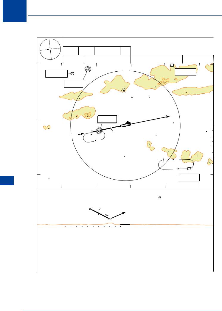
Figure 17.5 SRA approach
17.17 SRA. An SRA approach is a non-precision procedure using TAR and will therefore have a determined MDA/H. The procedure for SRA is similar to PAR except that in this case advisory height information is passed with range information e.g. “5 miles from touchdown, you should be passing one thousand five hundred and fifty feet”. SRA approaches always have an RTR
330