

- •Textbook Series
- •Contents
- •1 Definitions
- •Introduction
- •Abbreviations
- •Definitions
- •2 International Agreements and Organizations
- •The Chicago Convention
- •International Law
- •Commercial Considerations
- •Customs and Excise, and Immigration
- •International Obligations of Contracted States
- •Duties of ICAO Member States
- •Status of Annex Components
- •The International Civil Aviation Organization (ICAO)
- •The Organization of ICAO
- •Regional Structure of ICAO
- •Regional Structure and Offices
- •ICAO Publications
- •Other International Agreements
- •The Conventions of Tokyo, the Hague and Montreal
- •The Warsaw Convention
- •The Rome Convention
- •IATA
- •ECAC
- •EASA
- •Eurocontrol
- •World Trade Organization
- •Geneva Convention
- •EU Regulation 261/2004
- •Questions
- •Answers
- •3 Airworthiness of Aircraft
- •Introduction
- •Airworthiness
- •Questions
- •Answers
- •4 Aircraft Nationality and Registration Marks
- •Introduction
- •Nationality and Registration Marks
- •Certification of Registration
- •Aircraft Markings
- •Classification of Aircraft
- •Questions
- •Answers
- •5 Flight Crew Licensing
- •Introduction
- •Definitions
- •General Rules Concerning Licensing
- •Licences and Ratings for Pilots
- •Multi-crew Pilot Licence (MPL)
- •Instrument Rating (Aeroplane) (IR(A))
- •Instructor and Examiner Rating
- •JAR-FCL 3 Medical Requirements
- •Pilot Proficiency
- •EASA Theoretical Knowledge Examinations
- •Questions
- •Answers
- •6 Rules of the Air
- •History
- •Applicability of the Rules of the Air
- •General Rules
- •Visual Flight Rules
- •Instrument Flight Rules
- •Semi-circular Flight Level Rules and RVSM
- •Special VFR
- •Distress and Urgency Signals
- •Restricted, Prohibited or Danger Areas
- •Signals for Aerodrome Traffic
- •Marshalling Signals
- •Flight Deck Signals
- •Questions
- •Answers
- •Instrument Procedures
- •PANS OPS
- •Instrument Departure Procedures
- •Questions
- •Answers
- •8 Approach Procedures
- •Procedure Basics
- •Approach Procedure Design
- •Obstacle Clearance Altitude/Height
- •Operating Minima
- •Descent Gradients
- •Track Reversal and Racetracks
- •Missed Approach Segment and Procedure
- •Published Information
- •RNAV Approach Procedures based on VOR/DME
- •Questions
- •Answers
- •9 Circling Approach
- •Circling Approach
- •Questions
- •Answers
- •10 Holding Procedures
- •Holding Procedures
- •Entry Sectors
- •ATC Considerations
- •Obstacle Clearance
- •Questions
- •Answers
- •11 Altimeter Setting Procedure
- •Altimeter Setting Objectives
- •Transition
- •Phases of Flight
- •Questions
- •Answers
- •12 Parallel or Near-parallel Runway Operation
- •Safety
- •Runway Spacing
- •Questions
- •Answers
- •13 SSR and ACAS
- •Airborne Collision Avoidance System (ACAS)
- •Questions
- •Answers
- •14 Airspace
- •Introduction
- •Control Areas and Zones
- •Classes of Airspace
- •Required Navigation Performance (RNP)
- •Airways and ATS Routes
- •Questions
- •Answers
- •15 Air Traffic Services
- •Introduction
- •Air Traffic Control
- •ATC Clearances
- •Control of Persons and Vehicles at Aerodromes
- •The Flight Information Service
- •The Alerting Service
- •Procedures
- •Questions
- •Answers
- •16 Separation
- •Concept of Separation
- •Vertical Separation
- •Horizontal Separation
- •Radar Separation
- •Procedural Wake Turbulence Separation
- •Radar Wake Turbulence Separation
- •Visual Separation in the Vicinity of Aerodromes
- •Stacking
- •Questions
- •Answers
- •17 Control of Aircraft
- •Procedural ATC
- •Radar Control
- •Radar Identification
- •Radar Service
- •Aerodrome Control
- •Approach Control Service
- •Air Traffic Advisory Service
- •Aircraft Emergencies
- •Questions
- •Answers
- •18 Aeronautical Information Service (AIS)
- •Introduction
- •General
- •The Integrated Aeronautical Information Package
- •The Aeronautical Information Publication (AIP)
- •Notices to Airmen (NOTAM)
- •SNOWTAM
- •ASHTAM
- •Aeronautical Information Circulars (AICs)
- •Pre-flight and Post-flight Information
- •Questions
- •Answers
- •Introduction
- •Aerodrome Reference Code
- •Glossary of Terms
- •Aerodrome Data
- •Runways
- •Taxiways
- •Aprons
- •Questions
- •Answers
- •Requirements
- •Visual Aids for Navigation
- •Runway Markings
- •Taxiway Markings
- •Signs
- •Markers
- •Visual Docking Guidance Systems
- •Questions
- •Answers
- •21 Aerodrome Lighting
- •Aerodrome Lights
- •Approach Lighting Systems
- •Runway Lighting
- •Taxiway Lighting
- •Questions
- •Answers
- •22 Obstacle Marking and Aerodrome Services
- •Introduction
- •Visual Aids for Denoting Obstacles
- •Visual Aids for Denoting Restricted Use Areas
- •Emergency and Other Services
- •Other Aerodrome Services
- •Questions
- •Answers
- •23 Facilitation
- •Entry and Departure of Aircraft
- •Questions
- •Answers
- •24 Search and Rescue
- •Definitions and Abbreviations
- •Establishment and Provision of SAR Service
- •Co-operation between States
- •Operating Procedures
- •Questions
- •Answers
- •25 Security
- •Introduction
- •Objectives
- •Organization
- •Preventative Security Measures
- •Management of Response to Acts of Unlawful Interference
- •Further Security Information
- •Questions
- •Answers
- •26 Aircraft Accident and Incident Investigation
- •Introduction
- •Objective of Investigation
- •Investigations
- •Serious Incidents
- •EU Considerations
- •Questions
- •Answers
- •27 Revision Questions
- •Revision Questions
- •Answers
- •EASA Specimen Examination
- •Answers to Specimen EASA Examination
- •28 Addendum – EASA Part-FCL & Part-MED
- •Chapter Five. Flight Crew Licensing
- •European Aviation Safety Agency (EASA)
- •Licences
- •Ratings
- •Certificates
- •EASA Part-MED
- •29 Index

Separation 16
Radar Separation
16.32Separation Minima. Radar provides the ATCO with fairly accurate position information for an aircraft under his/her control. Problems associated with radar include: slant range display, target discrimination and loss of contact close to the radar overhead. These ‘errors’ must be handled in the same manner that other positional errors are: by the addition of ‘buffer’ allowances. The errors are worse for long range radars used in area control but must still be considered for terminal radars covering a much smaller area. The basic radar separation standard is 5 NM. This means that where two aircraft identified on radar are at the same level, they are not permitted to approach closer than 5 NM to each other on the radar display.
16.33Reduced Radar Separation. When approved by the authority and in specific circumstances, the radar separation standard (5 NM) may be reduced. The following describe these specific occasions:
•Radar capabilities. When radar capabilities so permit at a given location, the radar separation standard may be reduced to 3 NM.
•ILS Localizer. Where two (or more) aircraft are established on the same ILS localizer
course |
and within 10 NM |
of the threshold of the landing runway, the separation |
standard may be reduced to 2.5 |
NM between contacts on the radar display. |
|
•Simultaneous Parallel Approaches (Mode 2 - Dependent). During Mode 2 parallel runway operations radar separation is applied. Between aircraft on adjacent localizer courses the separation standard may be reduced to 2 NM between contacts on the radar display.
Procedural Wake Turbulence Separation
Separation 16
Figure 16.14
16.34 Situation. When the wings are creating lift (from ‘rotate’ to ‘touchdown’), wake vortices are created behind the aircraft. This is apparent in the form of turbulence, the severity of which is a function of aircraft mass, the worst case being a heavy aircraft at low speed. Where an aircraft is following another aircraft, allowance must be made for the ‘wake turbulence effect’ which under certain circumstance can be so severe as to cause structural damage (even catastrophic damage) to an airframe. The nature of the wake vortex is that it emanates from the wing tip in the form of spiralling air from the high pressure area below the wing to the low
303

16 Separation
Separation 16
pressure area above the wing. It spirals ‘in board’ towards the fuselage. The vortex exists at the level of the generating aircraft and to an altitude not exceeding 1000 ft below the generating aircraft. Where the following aircraft is within this airspace, wake turbulence separation must be applied.
16.35 Wake Turbulence Categories. Aircraft are categorized by maximum take-off mass (MTOM) to relate to the severity of the wake vortices generated. There are three categories as follows:
•Heavy - all aircraft types with MTOM equal to 136 000 kg or more
•Medium - aircraft types with MTOM less than 136 000 kg but more than 7000 kg
•Light - aircraft types with MTOM of 7000 kg or less
Note: MTOM is stated on the Certificate of Airworthiness for the aircraft.
16.36Separation Minima. The following procedural (non-radar) wake turbulence separation is applied. Note the criteria are only applicable where the following aircraft is ‘lighter’ than the preceding aircraft.
16.37Arriving Aircraft. Timed approaches:
•Medium behind a heavy - 2 minutes
•Light behind a medium or heavy - 3 minutes
16.38 Departing Aircraft. For a light or medium taking off behind a heavy, or a light behind a medium, a minimum of 2 minutes is applied when they are using:
•The same runway.
•Parallel runways separated by less then 760 m.
•Crossing runways if the projected flight paths cross at the same altitude or within 1000 ft below the heavier.
•Parallel runways separated by 760 m or more if the projected flight paths cross at the same altitude or within 1000 ft below the heavier.
304
Separation 16
Figure 16.15 Parallel runways
Separation 16
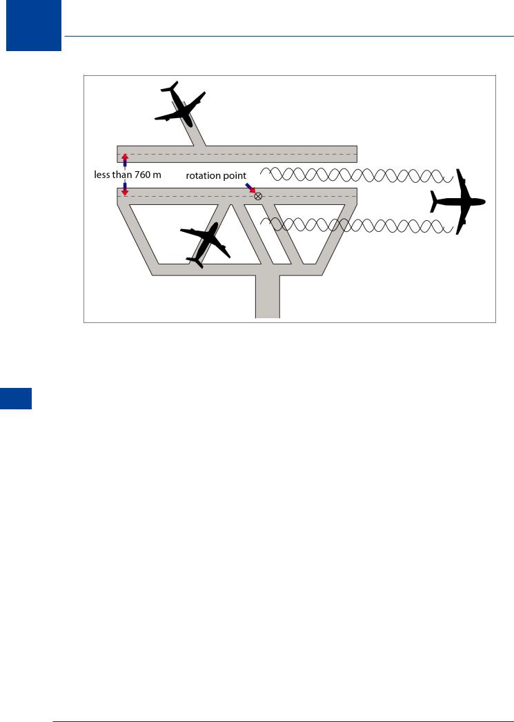
Figure 16.16 Parallel and crossing runways
305
16 Separation
Separation 16
Figure 16.17 Intermediate take-off
Note: Separation is increased to 3 minutes where a light or medium is taking off behind a heavy (or light behind a medium) from an intermediate part of the same runway or an intermediate point on parallel runways.
16.39 Displaced Landing Threshold. A separation of 2 minutes is applied between light or medium and heavy (or between light and medium) when operating on a runway with a displaced threshold when:
•A departing light or medium follows a heavy arriving, or a departing light follows a medium arriving, or
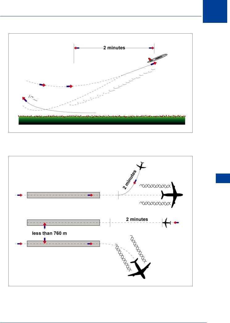
•An arriving light or medium follows a heavy departing, or an arriving light follows a medium departing, if the projected flight paths are expected to cross.
16.40 Opposite Direction. A separation of 2 minutes is applied between a light or medium and a heavy, or between a light and a medium, when the heavier aircraft is making a low or missed approach and the lighter aircraft is using an opposite direction runway for take-off, or is landing on the same runway in the opposite direction, or on a parallel opposite direction runway separated by less than 760 m.
306
Separation 16
Figure 16.18 Opposite direction for take-off
Separation 16
Figure 16.19 Opposite direction for landing
307