

Instrument Procedures - Departures |
|
7 |
|
||
|
|
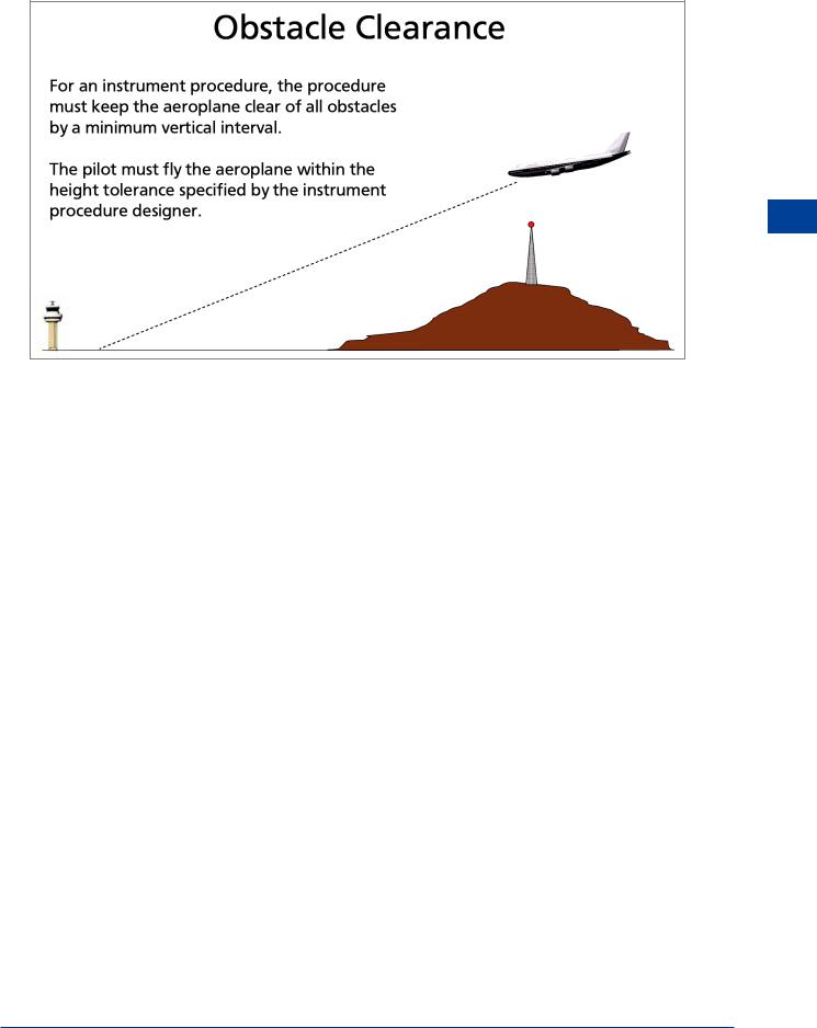
|
Figure 7.2
PANS OPS
7.4 Document8168. TheICAOdocumentthatspecifiestherecommendationsforinstrument procedures is PANS OPS. The term ‘PANS-OPS’ is commonly used to refer to the content of ICAO Doc 8168. The correct title of the document is “Procedures for Air Navigation Services - Aircraft Operations”. The document is printed in two volumes; Vol 1 - Flight Procedures; Vol 2 - Construction of Visual and Instrument Flight Procedures. Volume 1 describes operational procedures recommended for the guidance of flight operations personnel and we shall limit our considerations of instrument procedures to the content of Vol 1. Vol 1 outlines the various parameters on which the criteria of Vol 2 are based. Volume 2 is intended for the guidance of procedures specialists and describes the essential areas and obstacle clearance requirements for the achievement of safe, regular instrument flight operations. Both volumes present coverage of operational practices that are beyond the scope of Standards and Recommended Practices (SARPs) but with respect to which, a measure of international uniformity is desirable. PANs OPS, in expanding the SARPs of Annex 6, considers both departure and arrival procedures and to a lesser extent, en route procedures where obstacle clearance criteria should be taken into consideration.
Instrument Departure Procedures
7.5 General Criteria. These procedures assume that all engines are operating. The design of an instrument departure procedure is, in general, dictated by the terrain surrounding the aerodrome, but may also be required to cater for ATC requirements (adjacent ATS routes, restricted, prohibited or danger areas and the proximity of other aerodromes). These factors in turn influence the type and position of navigation aids required to provide track guidance for the departure route. Airspace restrictions may also affect the position of navigation aids. From the pilot and operator point of view, the use of automatic take-off thrust control systems (ATTCS) and noise abatement procedures will need to be taken into account as well. Where no suitable navigation aid is available to provide specific track guidance, the criteria for omnidirectional (any direction) departures is applied. Wherever possible a straight departure will be specified, which is aligned with the runway. Where a departure route requires a turn of more than 15° to avoid an obstacle, a turning departure is constructed.
Instrument Procedures - Departures 7
153
|
7 |
|
Instrument Procedures - Departures |
|||
7.6 |
Requirements. Where instrument departures are required, a departure procedure |
|||||
|
|
|
|
|||
|
|
|
|
will be established for each runway to be used, and will define the procedure for the various |
||
|
|
|
|
categories of aircraft based on an all engines running PDG of 3.3%, or an increased PDG if |
||
|
|
|
|
required to achieve minimum obstacle clearance. The procedures assume that pilots will |
||
|
|
|
|
compensate for wind effects (known or estimated) when flying departure routes which are |
||
|
|
|
|
expressed as tracks to be made good. If radar vectoring is applied, pilots are required to fly the |
||
|
|
|
|
vector headings and not make allowance for the wind. |
||
|
|
|
|
7.7 |
Obstacle Clearance. As already stated, obstacle clearance is a primary safety |
|
|
|
|
|
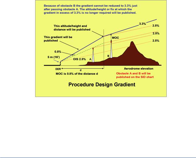
consideration in instrument departure procedures. Unless otherwise stated a PDG of 3.3% is |
||
|
|
|
|
assumed. The PDG is made up of 2.5% gradient of obstacle identification surfaces or the |
||
|
|
|
|
|||
7 |
|
|
gradient based on the most critical obstacle penetrating these surfaces (whichever is higher), |
|||
|
|
|
|
and 0.8% increasing obstacle clearance. Gradients published will be specified to an altitude/ |
||
Instrument |
||||||
height after which the minimum gradient of 3.3% is considered to exist. The final PDG |
||||||
|
|
|
|
|||
|
|
|
|
continues until obstacle clearance is ensured for the next phase of flight (en route, holding or |
||
-Procedures |
approach). At this point the departure procedure ends and is marked by a significant point. |
|||||
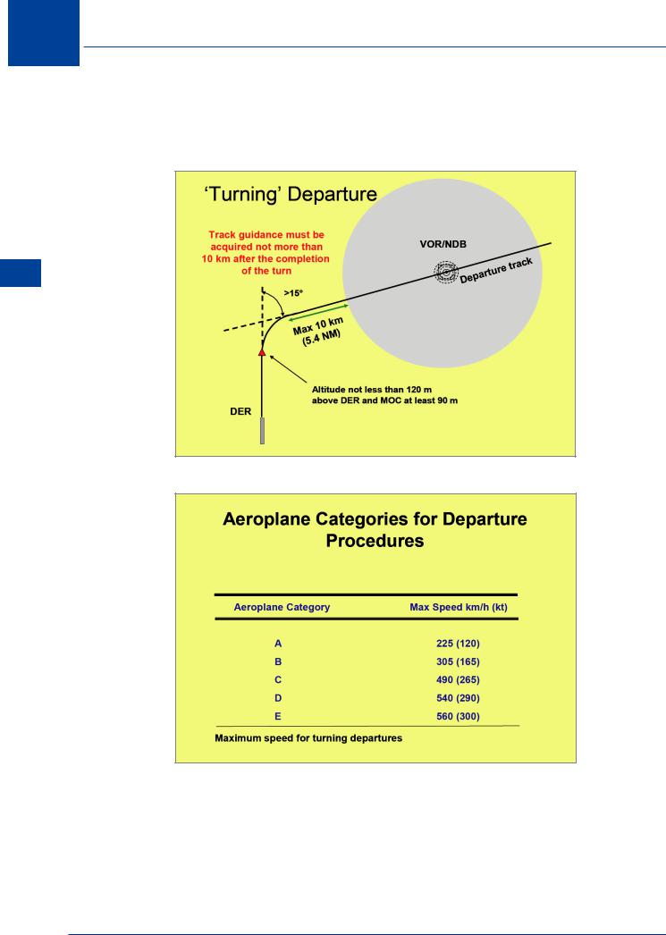
maximum divergence of 15°. In the turn initiation area for a turning departure a minimum |
||||||
|
|
|
|
The minimum obstacle clearance equals zero at the departure end of the runway (DER) and |
||
Departures |
thereafter increases by 0.8% of the horizontal distance in the direction of flight, assuming |
|||||
available. |
||||||
|
|
|
|
obstacle clearance of 90 m (295 ft) is provided. Increased obstacle clearance will be provided |
||
in mountainous terrain. If DME is available, additional height/distance information is made
Figure 7.3
7.8Mountainous Terrain. What defines mountainous terrain is not specified. In deciding if the criteria for mountainous terrain are applicable, the designer takes notice of the prevailing wind conditions. If the average wind speed of 37 kph or more produces significant down draughts, increased obstacle clearance is applied.
7.9Aircraft Category. It has already been mentioned that the major consideration in planning a departure route is to ensure adequate obstacle clearance. In determining the track over which the aircraft will fly speed is the determining factor. Aircraft are categorized by the
154
Instrument Procedures - Departures |
|
7 |
|
||
|
|
|
maximum speed that the departure procedure can be flown. Wherever limiting speeds other than those specified in the table are published, they must be complied with to remain within the appropriate areas. If an aeroplane operation requires a higher speed, then an alternative departure procedure must be requested.
Instrument Procedures - Departures 7
Figure 7.4
7.10Standard Instrument Departures. There are two basic types of departure route, straight, or turning. Departure routes are based on track guidance acquired within 20 km (10.8 NM) from the end of the runway (DER) for straight departures, and within 10 km (5.4 NM) after completion of turns for turning departures. When flying the route, the pilot is expected to correct for known wind and to remain within the protected airspace.
7.11Straight Departure. A straight departure is one in which the initial departure track is within 15° of the alignment of the runway. Track guidance may be provided by VOR, NDB or RNAV.
Figure 7.5
155
7 Instrument Procedures - Departures
7.12 Turning Departure. If the departure track requires a turn of more than 15°, a turning area is constructed and the turn required is commenced upon reaching a specified altitude/ height, or at a fix or at a facility (VOR, NDB etc...). Straight flight is assumed until reaching an altitude not less than 120 m (394 ft) above the elevation of the DER.
Departures - Procedures Instrument 7
Figure 7.6
Figure 7.7
7.13 Emergencies. It is the responsibility of the operator to establish procedures to cover the case of engine failure or an emergency in flight which occurs after V1.
156
Instrument Procedures - Departures |
|
7 |
|
||
|
|
|
Instrument Procedures - Departures 7
Figure 7.8
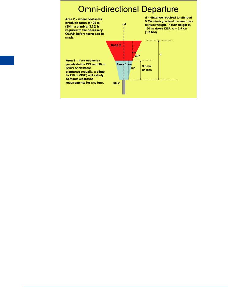
7.14 Omni-directional Departures. Where no track guidance is provided in the design of a departure procedure, the omni-directional method is used which basically provides for initial departure tracks to be undefined. In other words, once off the end of the runway and at a safe height, the aircraft can be navigated in any direction required to achieve the initial en route point. It may be that some sectors of the departure area may contain obstacles which preclude departures in that direction, in which case the published procedures will be annotated to show the restricted sectors. The basic procedure is that the aircraft will climb on the extended runway centre line to 120 m (394 ft) above aerodrome elevation before turns can be specified, and at least 90 m (295 ft) of obstacle clearance will be provided before turns greater than 15° can be specified. Turns will not commence within 600 m of the beginning of the runway. Where obstacles do not permit the development of omni-directional procedures, it is necessary to fly a departure route (straight or turning), or ensure that ceiling and visibility will permit obstacles to be avoided by visual means.
157
7 |
|
Instrument Procedures - Departures |
|
||
|
|
|
Departures - Procedures Instrument 7
Figure 7.9
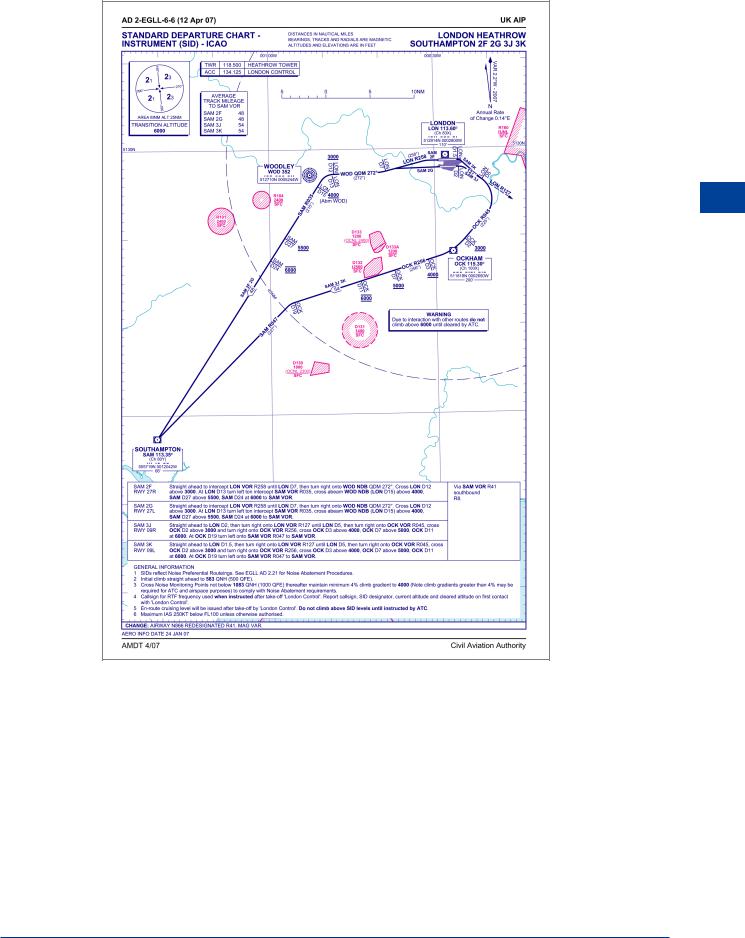
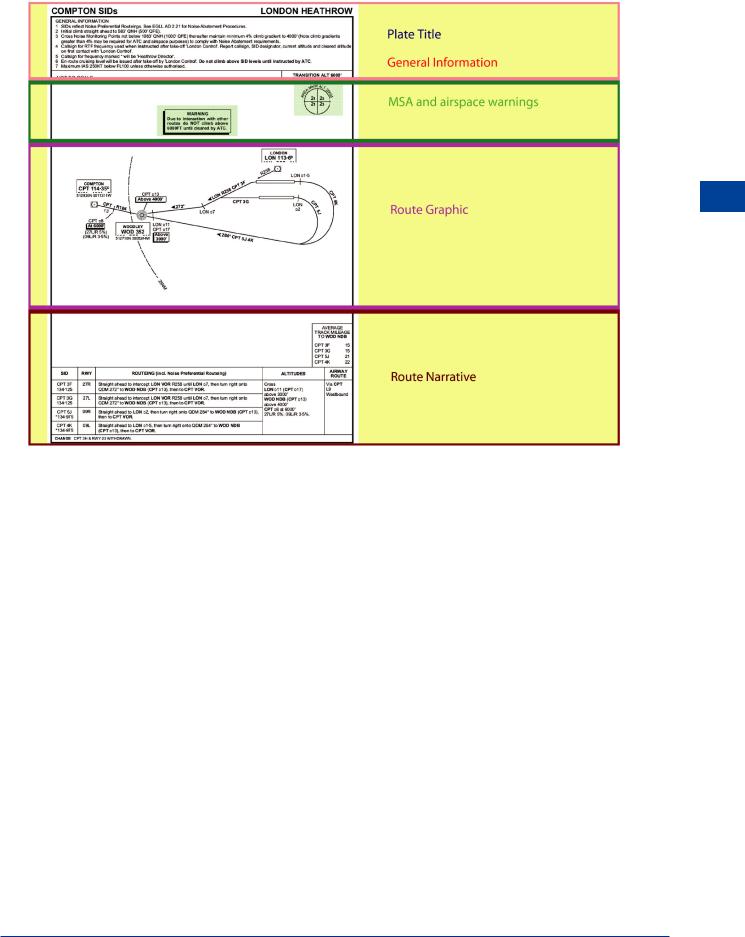
7.15 Published Information. Departure routes and SID charts are published in accordance with standards contained in Annex 11 and Annex 4 to the Chicago Convention. Departure routes are labelled as RNAV (area navigation based on VOR/DME or GPS) only when that is the primary means of navigation utilized. For omni-directional departures, the restrictions will be expressed as sectors to be avoided or sectors in which minimum gradients and/or minimum altitudes are specified to enable an aeroplane to safely over fly obstacles. Minimum Sector Altitude (MSA) is also depicted on the plate and gives the lowest safe altitude for a defined sector (based on a navigational facility) to a range of 25 NM from the aerodrome (or facility). Figure 7.10 shows a typical SID plate. This plate details the departures from the runways at Heathrow and specifies that the point of joining the ATS route structure is the Compton VOR (CPT). All SIDs start at DER and end at the point of joining the ATS en route system. Note that each route has a specific designator e.g. CPT3G. In the ATC clearance for IFR flights, departure instructions will include a SID to the first airways point. The ATCO will refer to the SID by its designator. Note the means by which track guidance is applied. In a normal aeroplane fully ‘airways fitted’ for IFR, the SID can always be complied with as there will be a minimum of two VOR/NAV boxes and one ADF. The Compton SID requires radio navigation using the LON and CPT VORs and the WOD NDB. DME is also specified.
The SID specifies DME distances to or from the facility with radials from VORs or QDMs for NDBs. The SID will also specify altitude restrictions in the form of “Above .....”, or “At .....”, as well as a diagram of the procedure. A narrative is always given in English. At the end of the SID the aircraft should be well placed to continue en route climbing in the airway or under radar control. At any time during the procedure, the pilot may be ordered to comply with radar vectoring requiring abandonment of the SID or abbreviation of the procedure. In such cases the pilot will be told that the aircraft is under radar control.
158
Instrument Procedures - Departures |
|
7 |
|
||
|
|
|
Instrument Procedures - Departures 7
Figure 7.10
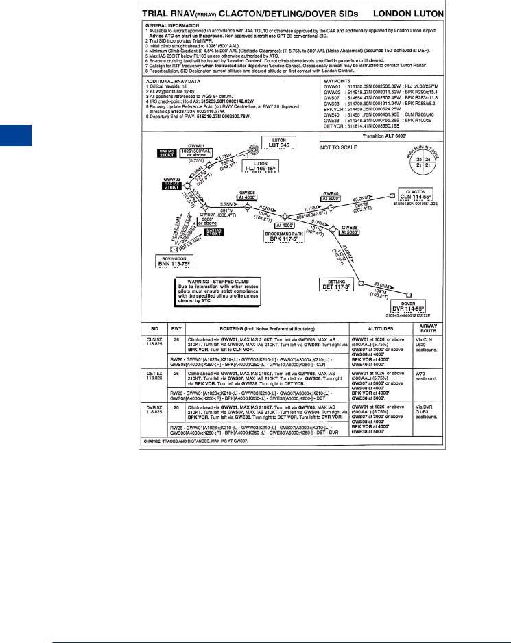
7.16Area Navigation (RNAV) and RNP Based Departure Procedures. The general principles relating to RNAV approach procedures also apply to RNAV departures based on a VOR/DME, DME/DME, basic GNSS and RNP criteria. Most FMS equipped aircraft are capable of following RNAV procedures but procedures may contain constraints on the system used. To use an RNP based procedure, the aircraft RNAV system must be approved for the published RNP and it must be confirmed before flight that the related VOR/DME stations are in fact working! Before flight, the pilot must also verify that the aircraft will be able to meet the RNP requirements for the segments to be flown as well as continue to monitor the system accuracy.
7.17Turns. There are four kinds of turn that may be specified for an RNAV procedure:
•Turn at a fly-by waypoint;
•Turn at a fly-over waypoint;
•Turn at an altitude/height; and
•Fixed radius turn (generally for RNP based procedures)
7.18 Use of FMS to Follow Conventional Departure Procedures. Where FMS is available, it may be used when flying the conventional departure procedures defined, provided the procedure is monitored using the basic display normally associated with that procedure, and the tolerances for flight using raw data on the basic display are complied with.
159
7 |
|
Instrument Procedures - Departures |
|
||
|
|
|
Departures - Procedures Instrument 7
Figure 7.11
160

Instrument Procedures - Departures |
|
7 |
|
||
|
|
|
Instrument Procedures - Departures 7
161