

- •Textbook Series
- •Contents
- •1 Definitions
- •Introduction
- •Abbreviations
- •Definitions
- •2 International Agreements and Organizations
- •The Chicago Convention
- •International Law
- •Commercial Considerations
- •Customs and Excise, and Immigration
- •International Obligations of Contracted States
- •Duties of ICAO Member States
- •Status of Annex Components
- •The International Civil Aviation Organization (ICAO)
- •The Organization of ICAO
- •Regional Structure of ICAO
- •Regional Structure and Offices
- •ICAO Publications
- •Other International Agreements
- •The Conventions of Tokyo, the Hague and Montreal
- •The Warsaw Convention
- •The Rome Convention
- •IATA
- •ECAC
- •EASA
- •Eurocontrol
- •World Trade Organization
- •Geneva Convention
- •EU Regulation 261/2004
- •Questions
- •Answers
- •3 Airworthiness of Aircraft
- •Introduction
- •Airworthiness
- •Questions
- •Answers
- •4 Aircraft Nationality and Registration Marks
- •Introduction
- •Nationality and Registration Marks
- •Certification of Registration
- •Aircraft Markings
- •Classification of Aircraft
- •Questions
- •Answers
- •5 Flight Crew Licensing
- •Introduction
- •Definitions
- •General Rules Concerning Licensing
- •Licences and Ratings for Pilots
- •Multi-crew Pilot Licence (MPL)
- •Instrument Rating (Aeroplane) (IR(A))
- •Instructor and Examiner Rating
- •JAR-FCL 3 Medical Requirements
- •Pilot Proficiency
- •EASA Theoretical Knowledge Examinations
- •Questions
- •Answers
- •6 Rules of the Air
- •History
- •Applicability of the Rules of the Air
- •General Rules
- •Visual Flight Rules
- •Instrument Flight Rules
- •Semi-circular Flight Level Rules and RVSM
- •Special VFR
- •Distress and Urgency Signals
- •Restricted, Prohibited or Danger Areas
- •Signals for Aerodrome Traffic
- •Marshalling Signals
- •Flight Deck Signals
- •Questions
- •Answers
- •Instrument Procedures
- •PANS OPS
- •Instrument Departure Procedures
- •Questions
- •Answers
- •8 Approach Procedures
- •Procedure Basics
- •Approach Procedure Design
- •Obstacle Clearance Altitude/Height
- •Operating Minima
- •Descent Gradients
- •Track Reversal and Racetracks
- •Missed Approach Segment and Procedure
- •Published Information
- •RNAV Approach Procedures based on VOR/DME
- •Questions
- •Answers
- •9 Circling Approach
- •Circling Approach
- •Questions
- •Answers
- •10 Holding Procedures
- •Holding Procedures
- •Entry Sectors
- •ATC Considerations
- •Obstacle Clearance
- •Questions
- •Answers
- •11 Altimeter Setting Procedure
- •Altimeter Setting Objectives
- •Transition
- •Phases of Flight
- •Questions
- •Answers
- •12 Parallel or Near-parallel Runway Operation
- •Safety
- •Runway Spacing
- •Questions
- •Answers
- •13 SSR and ACAS
- •Airborne Collision Avoidance System (ACAS)
- •Questions
- •Answers
- •14 Airspace
- •Introduction
- •Control Areas and Zones
- •Classes of Airspace
- •Required Navigation Performance (RNP)
- •Airways and ATS Routes
- •Questions
- •Answers
- •15 Air Traffic Services
- •Introduction
- •Air Traffic Control
- •ATC Clearances
- •Control of Persons and Vehicles at Aerodromes
- •The Flight Information Service
- •The Alerting Service
- •Procedures
- •Questions
- •Answers
- •16 Separation
- •Concept of Separation
- •Vertical Separation
- •Horizontal Separation
- •Radar Separation
- •Procedural Wake Turbulence Separation
- •Radar Wake Turbulence Separation
- •Visual Separation in the Vicinity of Aerodromes
- •Stacking
- •Questions
- •Answers
- •17 Control of Aircraft
- •Procedural ATC
- •Radar Control
- •Radar Identification
- •Radar Service
- •Aerodrome Control
- •Approach Control Service
- •Air Traffic Advisory Service
- •Aircraft Emergencies
- •Questions
- •Answers
- •18 Aeronautical Information Service (AIS)
- •Introduction
- •General
- •The Integrated Aeronautical Information Package
- •The Aeronautical Information Publication (AIP)
- •Notices to Airmen (NOTAM)
- •SNOWTAM
- •ASHTAM
- •Aeronautical Information Circulars (AICs)
- •Pre-flight and Post-flight Information
- •Questions
- •Answers
- •Introduction
- •Aerodrome Reference Code
- •Glossary of Terms
- •Aerodrome Data
- •Runways
- •Taxiways
- •Aprons
- •Questions
- •Answers
- •Requirements
- •Visual Aids for Navigation
- •Runway Markings
- •Taxiway Markings
- •Signs
- •Markers
- •Visual Docking Guidance Systems
- •Questions
- •Answers
- •21 Aerodrome Lighting
- •Aerodrome Lights
- •Approach Lighting Systems
- •Runway Lighting
- •Taxiway Lighting
- •Questions
- •Answers
- •22 Obstacle Marking and Aerodrome Services
- •Introduction
- •Visual Aids for Denoting Obstacles
- •Visual Aids for Denoting Restricted Use Areas
- •Emergency and Other Services
- •Other Aerodrome Services
- •Questions
- •Answers
- •23 Facilitation
- •Entry and Departure of Aircraft
- •Questions
- •Answers
- •24 Search and Rescue
- •Definitions and Abbreviations
- •Establishment and Provision of SAR Service
- •Co-operation between States
- •Operating Procedures
- •Questions
- •Answers
- •25 Security
- •Introduction
- •Objectives
- •Organization
- •Preventative Security Measures
- •Management of Response to Acts of Unlawful Interference
- •Further Security Information
- •Questions
- •Answers
- •26 Aircraft Accident and Incident Investigation
- •Introduction
- •Objective of Investigation
- •Investigations
- •Serious Incidents
- •EU Considerations
- •Questions
- •Answers
- •27 Revision Questions
- •Revision Questions
- •Answers
- •EASA Specimen Examination
- •Answers to Specimen EASA Examination
- •28 Addendum – EASA Part-FCL & Part-MED
- •Chapter Five. Flight Crew Licensing
- •European Aviation Safety Agency (EASA)
- •Licences
- •Ratings
- •Certificates
- •EASA Part-MED
- •29 Index
Aerodromes -Visual Aids, Markings and Signs 20
20.22 Runway Side Stripe Markings. Runway side stripe markings are to be provided between the thresholds of precision runways, and paved runways where there is a lack of contrast between the runway edges and the shoulders or the surrounding terrain. It is recommended that side stripes are marked on all precision runways regardless of the contrast with the surrounding ground. The picture of the runway at Gran Canaria, Figure 20.7 on the previous page, shows the use of side stripes.
Taxiway Markings
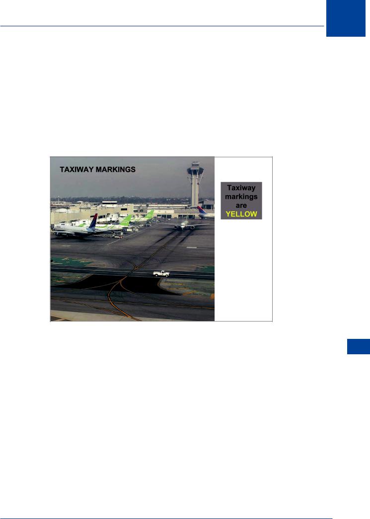
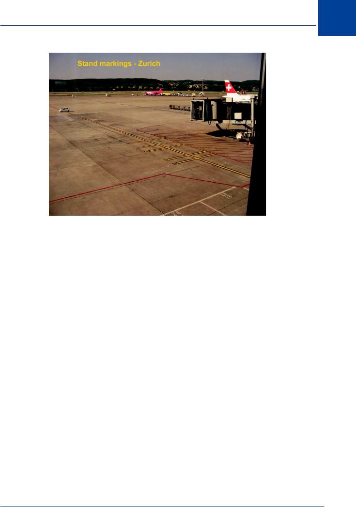
20.23 Requirements. Taxiway markings and aircraft stand markings are yellow. If there is a need to enhance conspicuity, the lines may be outlined in black.
© Paul Spijkars
Figure 20.8 Taxiway markings
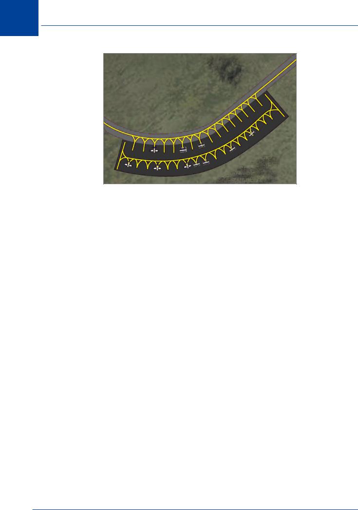
20.24 Apron Safety Lines. Although not strictly taxiway markings, in the apron areas the safe movement of aircraft into and out of parking stands can be enhanced by the use of apron safety lines. If all ground equipment and vehicles are parked or positioned behind the apron safety lines, a pilot or a marshaller can ignore the presence of those obstacles when parking aircraft. Apron safety lines are to be of a conspicuous colour which shall contrast with that used for aircraft stand markings.
Aerodromes - Visual Aids, Markings and Signs 20
399
20 Aerodromes -Visual Aids, Markings and Signs
Figure 20.9 Example of aircraft stand markings
20.25 Taxiway Centre Line Markings. Taxiway centre line markings are to be provided on a paved taxiway, de/anti-icing facility and the apron areas where the code number is 3 or 4 (and recommended for code 1 and 2). Centre line markings are to give guidance from the runway centre line, to the point on the apron where aircraft stand markings commence. Taxiway centre line markings are also provided on a paved runway when the runway is part of a standard taxi-route and there is no runway centre line marking; or where the taxiway centre line is not coincident with the runway centre line. Taxiway centre line marking is a continuous yellow line.
|
Should there be yellow side stripes, these mark non-load-bearing surfaces. |
|
|
20.26 Runway Holding Position Marking. Holding points are established at the entrance to |
|
|
all runways. It is not uncommon for there to be more than one holding point at the entrance |
|
|
to a runway. A runway holding position marking is to be displayed at a runway holding point. |
|
|
The actual holding position is indicated by the mandatory sign (see signs later in this chapter) |
|
|
which will be displayed on at least the left hand side of the taxiway as the aeroplane approaches |
|
|
the runway. Ideally the sign should be on both sides of the taxiway. The marking is to extend |
|
|
all the way across the taxiway. The position may be augmented by stop bars or runway guard |
|
20 |
||
lights, see paragraph 21.38. The distance between a runway holding position and the centre |
||
|
||
-Aerodromes |
line of the associated runway is specified in the picture after paragraph 19.53 and in the case of |
|
a precision approach runway, will be such that a holding aircraft (or vehicle) will not interfere |
||
|
||
|
with the operation of radio navigation aids, specifically ILS. A runway holding point may also |
|
SignsandMarkingsAids,Visual |
be established where the approach to a runway passes over a taxiway to another runway. In |
|
this case, the associated sign will specify what the holding point is for. |
||
|
400
Aerodromes -Visual Aids, Markings and Signs 20
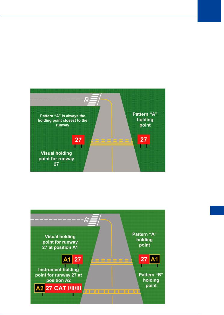
20.27Patterns. There are two distinct patterns for runway holding markings. These are defined as ‘Pattern A’ and ‘Pattern B’.
20.28Pattern A. The closest holding point to a runway will always be marked with a Pattern A marking, and it will be positioned at an intersection of a taxiway and a non-instrument (visual) runway, a non-precision approach runway or a take-off runway. Where a single taxiholding position is provided at an intersection of a taxiway and a precision approach category I II or III runway, the taxi-holding position marking shall be Pattern A. For a code 4 runway, the Pattern A holding point will be no closer than 75 m to the centre line of the runway. It is also the visual holding point.
Figure 20.10 Runway holding markings, pattern A
20.29 Pattern B. Where two or three taxi-holding positions are provided at such an intersection, the taxi-holding position marking closer (closest) to the runway shall be as shown in pattern A and the markings further from the runway shall be pattern B. Any other holding point associated with a runway required on a taxiway will also be Pattern B.
Aerodromes - Visual Aids, Markings and Signs 20
Figure 20.11 Runway holding markings, pattern B
401
20 Aerodromes -Visual Aids, Markings and Signs
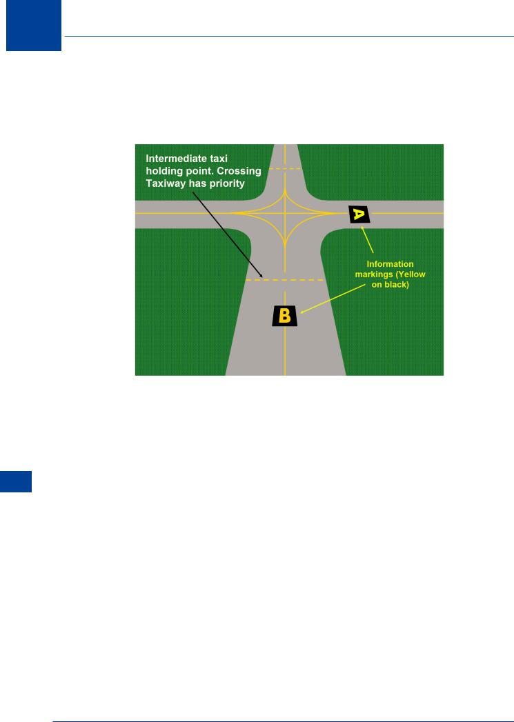
20.30 Intermediate Holding Position Marking. Where two (or more) taxiways cross, holding points are established at suitable distances from the crossing taxiway. It may be that one taxiway has priority and the holding point marking may be augmented by a mandatory marking. It should be coincident with a stop bar or clearance bar, where provided. A taxiway intersection marking consists of a single broken yellow line.
Signs and Markings Aids, Visual - Aerodromes 20
Figure 20.12 Intermediate holding position marking
20.31 Aircraft Stand Markings. Aircraft stand markings should be provided for designated parking positions on a paved apron and on de/anti-icing facilities. They should include such elements as stand identification, lead-in line, turn bar, turning line, alignment bar, stop line and lead-out line, as are required by the parking configuration and to complement other parking aids. The stand identification letter and/or number should be included a short distance after the beginning of the lead-in line. The height of the identification should be adequate to be readable from the cockpit of aircraft using the stand. Lead-in, turning and lead-out lines should normally be continuous in length. Where one or more sets of stand markings are superimposed on a stand, the lines should be continuous for the most demanding aircraft and broken for other aircraft. The curved portions of lead-in, turning and lead-out lines should have radii appropriate to the most demanding aircraft type for which the markings are intended. Where it is intended that aircraft proceed in one direction only, arrows pointing in the direction to be followed should be added as part of the lead-in and lead-out lines. A turn bar should be located at right angles to the lead-in line, abeam the left pilot position at the point of initiation of any intended turn. The distances to be maintained between the turn bar and the lead-in line may vary according to different aircraft types, taking into account the pilot’s field of view. An alignment bar should be placed so as to be coincident with the extended centre line of the aircraft in the specified marking position and visible to the pilot during the final part of the parking manoeuvre. A stop line should be located at right angles to the alignment bar, abeam the left pilot position at the intended point of stop.
402
Aerodromes -Visual Aids, Markings and Signs 20
|
© K. Boxall |
|
|
|
|
|
|
|
|
|
Figure 20.13 Aircraft stand markings |
|
||
20.32 Road holding Position Markings. Road holding position markings are to be provided |
|
|||
at all road entrances to a runway. The markings are to be located across the road at the holding |
|
|||
position, and will be marked in accordance with the local road traffic regulations. |
|
|||
20.33 Mandatory Information Marking. Where it is impracticable to install a mandatory |
|
|||
sign, a mandatory instruction marking is to be marked on the surface of the taxiway pavement. |
|
|||
Mandatory markings are holding point signs (runway designator in white on a red background) |
|
|||
and no entry signs. Pilots are not to pass any mandatory marking unless specifically cleared by |
|
|||
ATC. |
|
|||
20.34 Information Markings. Where an information sign would normally be installed but it |
|
|||
is physically impracticable, the information is to be displayed on the surface of the pavement. |
|
|||
20 |
||||
Where operationally required, an information sign should be supplemented by information |
||||
markings. The information markings should be displayed across the surface of the taxiway or |
|
|||
Signs |
||||
apron where necessary and positioned so as to be legible from the cockpit of an approaching |
||||
aircraft. Information markings shall consist of an inscription in yellow, when it replaces or |
and |
|||
supplements a location sign; and an inscription in black, when it replaces or supplements a |
Markings |
|||
direction or destination sign. Where there is insufficient contrast between the marking and |
||||
|
||||
the pavement surface, the marking shall include a black background where the inscriptions |
Aids, |
|||
are in yellow; and a yellow background where the inscriptions are in black. Markings will be |
||||
combinations of characters and symbols. Markings containing numbers only are only used for |
- Visual |
|||
runways and runway designators. |
||||
|
|
|
Aerodromes |
|
403